FM Series Gas Meter with Pulse Output - E-Mon
FM Series Gas Meter with Pulse Output - E-Mon
FM Series Gas Meter with Pulse Output - E-Mon

Create successful ePaper yourself
Turn your PDF publications into a flip-book with our unique Google optimized e-Paper software.
<strong>FM</strong> <strong>Series</strong> <strong>Gas</strong> <strong>Meter</strong><br />
<strong>with</strong> <strong>Pulse</strong> <strong>Output</strong><br />
Third-Party Products<br />
From The Manufacturer of E-<strong>Mon</strong> D-<strong>Mon</strong><br />
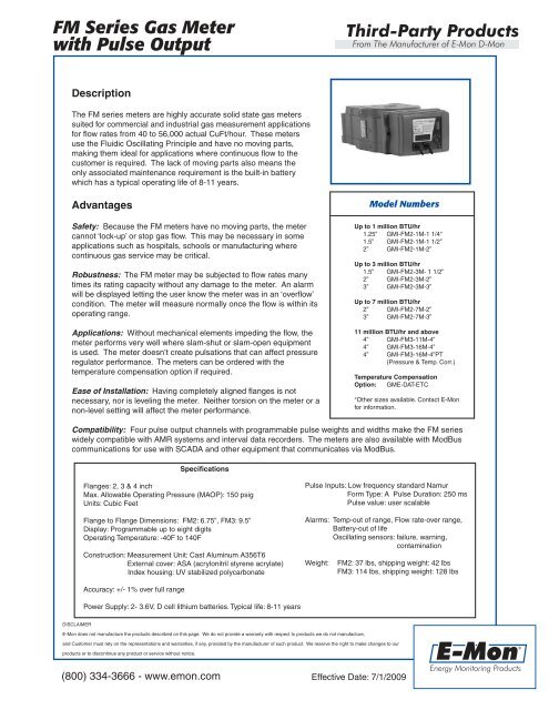
Description<br />
The <strong>FM</strong> series meters are highly accurate solid state gas meters<br />
suited for commercial and industrial gas measurement applications<br />
for flow rates from 40 to 56,000 actual CuFt/hour. These meters<br />
use the Fluidic Oscillating Principle and have no moving parts,<br />
making them ideal for applications where continuous flow to the<br />
customer is required. The lack of moving parts also means the<br />
only associated maintenance requirement is the built-in battery<br />
which has a typical operating life of 8-11 years.<br />
Advantages<br />
Safety: Because the <strong>FM</strong> meters have no moving parts, the meter<br />
cannot ‘lock-up’ or stop gas flow. This may be necessary in some<br />
applications such as hospitals, schools or manufacturing where<br />
continuous gas service may be critical.<br />
Robustness: The <strong>FM</strong> meter may be subjected to flow rates many<br />
times its rating capacity <strong>with</strong>out any damage to the meter. An alarm<br />
will be displayed letting the user know the meter was in an ‘overflow’<br />
condition. The meter will measure normally once the flow is <strong>with</strong>in its<br />
operating range.<br />
Applications: Without mechanical elements impeding the flow, the<br />
meter performs very well where slam-shut or slam-open equipment<br />
is used. The meter doesn’t create pulsations that can affect pressure<br />
regulator performance. The meters can be ordered <strong>with</strong> the<br />
temperature compensation option if required.<br />
Ease of Installation: Having completely aligned flanges is not<br />
necessary, nor is leveling the meter. Neither torsion on the meter or a<br />
non-level setting will affect the meter performance.<br />
Model Numbers<br />
Up to 1 million BTU/hr<br />
1.25” GMI-<strong>FM</strong>2-1M-1 1/4“<br />
1.5” GMI-<strong>FM</strong>2-1M-1 1/2”<br />
2” GMI-<strong>FM</strong>2-1M-2”<br />
Up to 3 million BTU/hr<br />
1.5” GMI-<strong>FM</strong>2-3M- 1 1/2”<br />
2” GMI-<strong>FM</strong>2-3M-2”<br />
3” GMI-<strong>FM</strong>2-3M-3”<br />
Up to 7 million BTU/hr<br />
2” GMI-<strong>FM</strong>2-7M-2”<br />
3” GMI-<strong>FM</strong>2-7M-3”<br />
11 million BTU/hr and above<br />
4” GMI-<strong>FM</strong>3-11M-4”<br />
4” GMI-<strong>FM</strong>3-16M-4”<br />
4” GMI-<strong>FM</strong>3-16M-4”PT<br />
(Pressure & Temp. Corr.)<br />
Temperature Compensation<br />
Option: GME-DAT-ETC<br />
*Other sizes available. Contact E-<strong>Mon</strong><br />
for information.<br />
Compatibility: Four pulse output channels <strong>with</strong> programmable pulse weights and widths make the <strong>FM</strong> series<br />
widely compatible <strong>with</strong> AMR systems and interval data recorders. The meters are also available <strong>with</strong> ModBus<br />
communications for use <strong>with</strong> SCADA and other equipment that communicates via ModBus.<br />
Specifications<br />
Flanges: 2, 3 & 4 inch<br />
Max. Allowable Operating Pressure (MAOP): 150 psig<br />
Units: Cubic Feet<br />
Flange to Flange Dimensions: <strong>FM</strong>2: 6.75”, <strong>FM</strong>3: 9.5”<br />
Display: Programmable up to eight digits<br />
Operating Temperature: -40F to 140F<br />
Construction: Measurement Unit: Cast Aluminum A356T6<br />
External cover: ASA (acrylonitril styrene acrylate)<br />
Index housing: UV stabilized polycarbonate<br />
<strong>Pulse</strong> Inputs: Low frequency standard Namur<br />
Form Type: A <strong>Pulse</strong> Duration: 250 ms<br />
<strong>Pulse</strong> value: user scalable<br />
Alarms: Temp-out of range, Flow rate-over range,<br />
Battery-out of life<br />
Oscillating sensors: failure, warning,<br />
contamination<br />
Weight:<br />
<strong>FM</strong>2: 37 lbs, shipping weight: 42 lbs<br />
<strong>FM</strong>3: 114 lbs, shipping weight: 128 lbs<br />
Accuracy: +/- 1% over full range<br />
Power Supply: 2- 3.6V, D cell lithium batteries. Typical life: 8-11 years<br />
DISCLAIMER<br />
E-<strong>Mon</strong> does not manufacture the products described on this page. We do not provide a warranty <strong>with</strong> respect to products we do not manufacture,<br />
and Customer must rely on the representations and warranties, if any, provided by the manufacturer of such product. We reserve the right to make changes to our<br />
products or to discontinue any product or service <strong>with</strong>out notice.<br />
®<br />
(800) 334-3666 - www.emon.com<br />
Effective Date: 7/1/2009<br />
Energy <strong>Mon</strong>itoring Products
<strong>FM</strong> <strong>Series</strong> <strong>Gas</strong> <strong>Meter</strong><br />
<strong>with</strong> <strong>Pulse</strong> <strong>Output</strong><br />
Third-Party Products<br />
From The Manufacturer of E-<strong>Mon</strong> D-<strong>Mon</strong><br />
Model A B C D Thread Depth<br />
<strong>FM</strong>2 16.5” 10.6” 6.75” 10” 1”<br />
<strong>FM</strong>3 23.7” 16.5” 9.5” 15.2” 1”<br />
Model Flange Type Bolt Pattern Diameter<br />
<strong>FM</strong>2 ANSI 125 2” 4.75”<br />
<strong>FM</strong>2 ANSI 125 3” 6.00”<br />
<strong>FM</strong>3 ANSI 125 4” 7.50”<br />
Fluidic Oscillation Principle<br />
The operation of the <strong>FM</strong> meter is based on the fluidic oscillation principle. The measurement unit is<br />
comprised of three functional sections; the flow conditioner, jet nozzle formation and fluidic oscillation<br />
chamber.<br />
<strong>Gas</strong> enters (1) the meter and divides into two separate flow paths (2). These two paths recombine (3) as<br />
they exit the flow conditioner and enter the fluidic oscillation chamber through the nozzle. The process<br />
of dividing the flow eliminates upstream disturbances and creates well conditioned flow.<br />
In the fluidic oscillating chamber, a jet is formed (4) as the gas enters through the nozzle. The jet then<br />
starts oscillating back and forth (5). Thermal sensors located just after the nozzle detect a temperature<br />
variance as the jet passes from one side to the other.<br />
The volume of gas passed through the meter is obtained by counting the number of oscillations<br />
detected by the sensors.<br />
DISCLAIMER<br />
E-<strong>Mon</strong> does not manufacture the products described on this page. We do not provide a warranty <strong>with</strong> respect to products we do not manufacture,<br />
and Customer must rely on the representations and warranties, if any, provided by the manufacturer of such product. We reserve the right to make changes to our<br />
products or to discontinue any product or service <strong>with</strong>out notice.<br />
®<br />
(800) 334-3666 - www.emon.com<br />
Effective Date: 7/1/2009<br />
Energy <strong>Mon</strong>itoring Products