
Create successful ePaper yourself
Turn your PDF publications into a flip-book with our unique Google optimized e-Paper software.
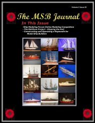
<strong>March</strong> 2007<br />
In This Issue:<br />
- Selecting Saw Blades<br />
- Frame Lofting Practicum -<br />
Part I<br />
- From the files of<br />
<strong>Ship</strong>WreckCentral<br />
and more...<br />
The MSB Journal
Volume 1, Issue 1<br />
<strong>March</strong> 2007<br />
© www.modelshipbuilder.com<br />
All articles published in The MSB Journal<br />
are covered under international copyright laws.<br />
This newsletter may be re-distributed freely as long as it remains,<br />
whole, intact and un-altered. We also urge you to print a copy<br />
for your workshop or reading area.<br />
Published by<br />
www.modelshipbuilder.com<br />
Front Cover<br />
Photo<br />
Mr. John Reid<br />
Montreal, Quebec, Canada<br />
How to Contact The MSB Journal<br />
By email: msbjournal@modelshipbuilder.com<br />
By Snail-Mail<br />
<strong>Model</strong><strong>Ship</strong><strong>Builder</strong>.com<br />
c/o Winston Scoville<br />
5 St. Charles Place RR 5<br />
Clinton, Ontario, N0M 1L0<br />
Canada<br />
The MSB Journal<br />
www.modelshipbuilder.com<br />
1
In This Issue<br />
EDITORS NOTES.................................................................................................3<br />
LETTERS TO THE EDITOR.................................................................................4<br />
SO YOU WANT TO BUILD A MODEL SHIP .....................................................5<br />
SHIP MODELS ON THE INTERNET....................................................................7<br />
SELECTING SAW BLADES FOR YOUR TABLE SAW ......................................9<br />
SHIPS FROM THE PAST...................................................................................14<br />
JIGS& THINGS...................................................................................................15<br />
HISTORICAL SHIPS OF ANOTHER NATURE..................................................16<br />
FRAME LOFTING PRACTICUM – PART I ........................................................17<br />
FROM THE FILES OF SHIPWRECKCENTRAL ................................................23<br />
CLUBS & ORGANIZATIONS WITH A WEB PRESENCE .................................24<br />
THE MSB JOURNAL CLASSIFIEDS.................................................................25<br />
NAUTICAL ENTERTAINMENT..........................................................................26<br />
The MSB Journal<br />
www.modelshipbuilder.com<br />
2
Editors Notes<br />
Winston Scoville<br />
winston@modelshipbuilder.com<br />
Welcome to the inaugural issue of The MSB Journal. An online<br />
magazine style newsletter created by <strong>Model</strong> <strong>Ship</strong> <strong>Builder</strong>s for <strong>Model</strong><br />
<strong>Ship</strong> <strong>Builder</strong>s.<br />
We hope that you enjoy your reading experience and we encourage you to send us<br />
comments or suggestions for future issues.<br />
To help make this a truly reader friendly newsletter we hope that you will take part<br />
in its development. This can be done in numerous ways, from merely dropping us a<br />
line of encouragement, submitting articles, recommending future articles and<br />
content, to simply passing on the word about where people can download their copy<br />
of The MSB Journal.<br />
Have a flair for writing We’re also looking for regular columnists covering all areas<br />
of model building. Share your knowledge so that others may learn.<br />
Maybe you’re not a writer, but have an interesting project on the go. Contact us with<br />
the details and we’ll see what we can do. All input is welcome.<br />
How you participate is up to you. The most important aspect is that you participate.<br />
Okay, enough from me….lets get on to the newsletter, there’s lots of great<br />
information in this issue.<br />
To contact us:<br />
msbjournal@modelshipbuilder.cm<br />
To subscribe to The MSB Journal:<br />
www.modelshipbuilder.com/msbjournal<br />
The MSB Journal<br />
www.modelshipbuilder.com<br />
3
Letters to the Editor<br />
Letters to the editor will be published in this section. For obvious reason you don’t see any here<br />
this month. Send us your emails and we’ll post them here. Have questions Comments Or are<br />
just looking for information Let us know by sending an email to<br />
msbjournal@modelshipbuilder.com<br />
.<br />
The MSB Journal<br />
www.modelshipbuilder.com<br />
4
So you want to build a model ship<br />
So you want to build a model ship You looked around<br />
went to all the shops or visited all the stores online and<br />
you’ve decided that you’d like to build the HMS Victory<br />
as your first build. Its got everything you’ve always<br />
wanted in a model ship, lots of lines and things, lots of<br />
cannons, beautiful looking wood…boy is that ever going<br />
to look good in your office. So you go out and pay<br />
$500.00 for the kit and begin to build……..<br />
Sadly, this is what a lot of potential model builders do,<br />
only to be frustrated by the level of skill that is required<br />
to build the model of that level not to mention the<br />
hundreds if not thousands of hours that can go into<br />
building it. So much so, that a lot of once enthusiastic<br />
people turn their backs on model building never to<br />
return, thinking that it is above and beyond them.<br />
The fact is, like anything that is worth doing well, there<br />
is a learning curve. We all have to start somewhere and<br />
the absolute best place to start is with the very basics.<br />
<strong>Model</strong> building in an ongoing life long experience. You<br />
will never know all there is to know. This became<br />
apparent to me recently when a good friend of mine was getting to the rigging<br />
portion of his build. He was stumped. It took him a couple of weeks to figure things<br />
out. That surprised me due to the fact that he has been building models now for over<br />
50 years.<br />
So where do we start to learn Well, I do not proclaim this to be to do all to end all<br />
but if I might be so humble as to make some suggestions…<br />
First, you should do some reading on the subject. This should give you a solid<br />
foundation on what will be required of you or at least an outline of the basic<br />
minimum skills you’ll need to master. A couple of books that I have found quite<br />
helpful and would have no trouble recommending are “Historic <strong>Ship</strong> <strong>Model</strong>s by<br />
Wolfram zu Mondfeld” (ISBN 1-4027-2186-2) and “<strong>Ship</strong> <strong>Model</strong>ing from Stem to Stern<br />
by Milton Roth” (ISBN 0-8306-2844-4). You should be able to find these books at<br />
any well stocked bookstore or hobby shop (If not we have them available through<br />
the bookstore at our website…I know…shameless plug).<br />
I would also recommend that you get in touch with other model builders and get<br />
suggestions from them. You can do this by attending a local meeting at a modeling<br />
club in your area or through the internet where you will find many discussion forums<br />
that are very active.<br />
So you’ve done some reading and you want to get started. Which model should you<br />
select as your first build Most model manufacturers offer models that are geared<br />
towards the novice builder. Have a look at their offerings and see which ones appeal<br />
to you. For your first model, try to keep it as simple as possible while still<br />
maintaining your interest.<br />
The MSB Journal<br />
www.modelshipbuilder.com<br />
5
Being able to complete a model at this level will provide you with some of the basic<br />
skills you need for taking on that next project. Here to, do not leave yourself to the<br />
whims of the instructions that you get with this kit. Check around and see what<br />
others have done, see if they’ve encountered any problems with their build and how<br />
they overcame them. Though not intentional you will find that a lot of model kits<br />
leave a lot to be desired when it comes to their instructions. Especially those that are<br />
created in a different language and have to be translated as they can lose a lot of<br />
their meanings in the translations.<br />
Another learning aide for you to be aware of are Practicums. These are highly<br />
detailed instruction manuals that are written by model builders and are based on a<br />
given or specific kit.<br />
Regardless of how you start it is important that you do some homework before you<br />
go jumping off the deep end. Doing so will help you avoid spending money<br />
needlessly on a model that is way beyond your current capabilities. Don’t worry,<br />
you’ll get to build that highly detailed HMS Victory down the road when you are<br />
ready for it and you’ll be a lot happier with the results of your efforts.<br />
In the next issue, we’ll have a look at some of the basic tools that you’ll need in your<br />
shipyard tool-bin…<br />
Recommended Reading Material<br />
All books available through www.modelshipbuilder.com<br />
or any well stocked hobby shop<br />
The MSB Journal<br />
www.modelshipbuilder.com<br />
6
<strong>Ship</strong> <strong>Model</strong>s On The Internet<br />
Sid Siegal, John Green, sisiegelmd@charter.net<br />
As ship modelers what do we want to see on the Internet I’m sure every ship<br />
modeler can give a different answer. Obviously, the web is a major portal to<br />
historical research. It’s also a great way to find technical answers and assistance.<br />
But there’s another facet of the web that is very important: to recognize<br />
achievement and excellence in the art of ship modeling.<br />
<strong>Ship</strong> modeling is an art that demands knowledge and understanding of history and<br />
maritime technology as well as<br />
skilled craftsmanship. Authentic<br />
ship models are rare and not<br />
readily available for viewing. But<br />
looking at ship models is one of<br />
the best ways for modelers to<br />
improve the quality and<br />
sophistication of their work.<br />
There are many websites that<br />
show images of ship models, but<br />
few that accurately and succinctly<br />
describe the model or provide a<br />
possible source for further<br />
research. Often there is much about the history of the subject ship, but little about<br />
the model itself, beyond the vague description that it is “museum quality”, whatever<br />
that means.<br />
John Green of Maritime <strong>Ship</strong> <strong>Model</strong>ers Guild in Halifax, Nova Scotia, and Sid Siegel of<br />
<strong>Ship</strong> <strong>Model</strong>ers Association of Southern California established a couple of websites to<br />
give independent ship modelers an opportunity to exhibit their work. The Marine<br />
<strong>Model</strong> Artists Cooperative (www.shipmodelco-op.com) was structured as a sort of<br />
exchange or venue where excellent ship models by independent builders are<br />
accurately described and offered for sale, without commission or fees of any kind.<br />
The purpose was not just to sell models, but to educate the public that fine authentic<br />
ship models are rare and valuable,<br />
and to try to counter the public<br />
impression that ship models come<br />
out of a box and are all pretty<br />
much alike and not worth more<br />
than the price of a good bowling<br />
ball. For those modelers who do<br />
not care to sell their models, the<br />
<strong>Ship</strong> <strong>Model</strong> Registry<br />
(www.registryofshipmodels.org)<br />
offers the opportunity to have their<br />
work exhibited in a more academic<br />
venue and become part of a<br />
database for future research. This<br />
is a new website and actively seeking participants who wish to record and exhibit<br />
their completed models or even show any heirloom models in their possession. Both<br />
websites are meant to be used as research sources, or simply to show other<br />
The MSB Journal<br />
www.modelshipbuilder.com<br />
7
modelers’ takes on various subjects. One obstacle to these enterprises has been the<br />
difficulty of getting good photographs that do justice to the models.<br />
There are many websites that feature ship models, and it is not easy to get attention<br />
in crowded cyberspace. We hope the above entries will be useful to independent ship<br />
modelers in reaching their colleagues as well as the general public.<br />
Sid Siegel<br />
John Green<br />
From the Archives of the National Maritime Museum<br />
Elephant 1786<br />
Scale: 1:48. Plan showing the sheer lines with inboard detail, and longitudinal half-breadth for<br />
‘Elephant’ (1786), two-decker, 74-gun, third-rate ship of war. ‘Elephant’ was built in 1786 as one<br />
of the ‘Arrogant’ class of 74-gun ships, a slight modification of the ‘Bellona’ class.<br />
‘Elephant’ was Nelson's flagship at the Battle of Copenhagen in 1801 and it was as he was<br />
walking the starboard side of the quarterdeck that a Danish cannonball sent splinters flying<br />
around him. He remarked to another officer, ‘Warm work. But, mark you, I would not be<br />
elsewhere for thousands.’<br />
Source: www.nmm.ac.uk<br />
The MSB Journal<br />
www.modelshipbuilder.com<br />
8
Selecting Saw Blades for your Table Saw<br />
Rockler Woodworking – www.rockler.com<br />
When in your workshop, whether you are cutting wood on a large table saw or your<br />
bench-top mini table saw it is important to select the most appropriate blade to do<br />
the job. In the following pages we are going to look at how to select just that blade.<br />
Understanding these basic elements of blade design will provide even the novice with<br />
enough information to properly select blades for their table saw needs in the<br />
workshop.<br />
So how do I pick out the right saw blade<br />
Selecting saw blades isn’t really all that complicated, you just need to know a little<br />
about what different types of saw blades do best, and about what separates topquality<br />
saw blades from the rest of the pack.<br />
Saw Blade Basics<br />
In general, regardless of their size, saw blades are designed to handle specific types<br />
of cutting operations. There are blades that are designed for crosscutting wood,<br />
ripping wood, cutting veneered plywood and panels etc. There are also “general<br />
purpose” and “combination” blades, which are designed to work well in two or more<br />
types of cutting operations.<br />
There are a number of factors that determine what a blade does best.<br />
<br />
<br />
<br />
<br />
Number of teeth<br />
Type of gullet<br />
Tooth configuration<br />
and the hook angle<br />
Number of teeth<br />
In general, blades with more teeth will yield a smoother cut, while blades with<br />
fewer teeth move material faster. A blade designed for ripping lumber, for<br />
example, usually has as few as 24 teeth, and is designed to quickly move<br />
material along the length of the grain. A rip blade isn't designed to yield a<br />
mirror-smooth cut, but a good rip blade will move through hardwood with<br />
little effort and leave a clean cut with a minimum of scoring.<br />
A crosscut blade, on the other hand, is designed to give you a smooth cut<br />
across the grain of the wood, without any splintering or tearing of the material.<br />
A crosscut blade will usually have from 60 to 80 teeth. Here, more teeth mean<br />
that each tooth has to move less material. A crosscut blade makes many more<br />
individual cuts as it moves through the stock than a ripping blade. The result is<br />
a cleaner cut on edges and a smoother cut surface. With a top-quality crosscut<br />
blade, the cut surface will appear polished.<br />
The MSB Journal<br />
www.modelshipbuilder.com<br />
9
Gullets<br />
The gullet is the space cut away from the blade plate in front of each tooth to allow<br />
for chip removal. In a ripping operation, the feed rate is faster than in crosscutting<br />
and the chip size is bigger, so the gullet needs to be deep enough to make room for<br />
the large amount of material it has to handle. In a crosscutting blade the chips are<br />
smaller and fewer per tooth, so the gullet is much smaller. The gullets on some<br />
crosscutting blades are purposely sized small to inhibit a too-fast feed rate, which<br />
can be a problem, especially on radial arm and sliding miter saws.<br />
The gullets of a combination blade are designed to handle both<br />
ripping and crosscutting. The large gullets between the groups of<br />
teeth help clear out the larger amounts of material generated in<br />
ripping. The smaller gullets between the grouped teeth inhibit a<br />
too-fast feed rate in crosscutting.<br />
Tooth Configuration<br />
The shape of the saw blade tooth and the way the teeth are grouped also affect the<br />
way the blade cuts. The configuration of the teeth on a saw blade has a lot to do<br />
with whether the blade will work best for ripping, crosscutting, or laminates.<br />
Flat Top (FT) Flat top teeth are used on blades made for ripping hard and<br />
soft woods. Since wood is much less likely to chip and splinter when it is<br />
being cut in the direction of the grain, the focus of a rip blade is to<br />
quickly and efficiently remove material. The flat top tooth is the most<br />
efficient design for cutting and raking material out of the cut.<br />
Alternate Top Bevel (ATB) "Alternate top bevel" means that the saw blade<br />
teeth alternate between a right and left hand bevel. This tooth<br />
configuration gives a smoother cut when crosscutting natural woods and<br />
veneered plywood. The alternating beveled teeth form a knife-like edge<br />
on either side of the blade and make a cleaner cut than flat top teeth.<br />
Combination Tooth (Comb.) The combination (4&1) configuration is used<br />
for "combination" blades -- blades designed to do both crosscutting and<br />
ripping. The teeth are arranged in groups of five - four ATB teeth and one<br />
FT -- with a large gullet in between the groups.<br />
Triple Chip Grind (TCG) The TCG configuration excells at cutting hard<br />
materials like laminates, MDF, and plastics. Teeth alternate between a flat<br />
raking tooth and a higher "trapeze" tooth. The TCG configuration is also<br />
used for non-ferrous metal cutting blades.<br />
High Alternate Top Bevel (HiATB) The HiATB configuration is used<br />
for extra-fine crosscutting and to cut materials surfaced with melamine,<br />
which is prone to chipping. The high bevel angle increases the knife-like<br />
action at the edge of the blade.<br />
The MSB Journal<br />
www.modelshipbuilder.com<br />
10
Hook Angle<br />
On most saw blades, the tooth faces are tipped either toward or away from the<br />
direction of rotation of the blade, rather than being perfectly in line with the center of<br />
the blade. Hook angle is the angle formed between the tooth face and a line drawn<br />
from the center of the blade across the tip of the tooth. On a blade with a positive<br />
hook angle, the teeth are tipped toward the direction of the blade's rotation. A<br />
negative hook angle means that teeth tip away from the direction of rotation, and a<br />
zero degree hook angle means that the teeth are in line with the center of the blade.<br />
Hook angle affects blade operation in important ways. A blade with high positive<br />
hook angle (+20 degrees is a high hook angle) will have a very aggressive cut and a<br />
fast feed rate. A low or negative hook angle will slow the feed rate and will also<br />
inhibit the blade's tendency to "climb" the material being cut. A blade for ripping<br />
lumber on a table saw will generally have a high hook angle, where an aggressive,<br />
fast cut is usually what you want. Radial arms saws and sliding compound miter<br />
saws, on the other hand, require a blade with a very low or negative hook angle, to<br />
inhibit overly fast feed rate, binding, and the blade's tendency to try to "climb" the<br />
material.<br />
Kerf Width and Plate Thickness<br />
The width of the "kerf" -- the slot the blade cuts in the material - is another<br />
important consideration. Most obviously, the kerf width determines the amount of<br />
material that is expended in the cutting process. But kerf width isn't just a matter of<br />
economics. The size of the kerf is determined in part by the thickness of the blade<br />
plate, and a solid, reliable blade plate is one of the features of a good saw blade.<br />
Thin Kerf Blades<br />
A saw blade's teeth, of course, have to make a<br />
wide enough cut to allow the blade plate to pass<br />
through the kerf. And for the blade to operate<br />
smoothly and make a true cut without a lot of<br />
scoring on the edge of the cut, the blade plate has<br />
to be substantial enough to absorb vibration and<br />
to handle the heat generated during the cut. For<br />
full kerf saw blade, a kerf width of around 1/8'' is<br />
standard. But for so called "underpowered"<br />
saws -- under 3 HP for a table saw -- a full 1/8''<br />
kerf has another effect: drawing too much power<br />
from the tool. If not enough power is delivered to<br />
The laser-cut reeds in this<br />
Freud thin kerf blade are<br />
filled with a vibration<br />
dampening material to<br />
keep the blade running<br />
straight and smooth.<br />
the blade, the saw slows down causing excessive friction. The blade heats up and<br />
can become distorted or burn the cut surface.<br />
Fortunately for woodworkers who don't own the most powerful industrial equipment -<br />
- and for those of us who just hate to watch expensive hardwood turn into piles of<br />
chips -- technological advances in blade design have generated "thin kerf" blades<br />
that rival the best industrial quality full kerf saw blades. Thin kerf saw blades are<br />
extremely helpful for underpowered saws for the simple reason that the blade has to<br />
cut through less material, and therefore doesn't have to work as hard as a blade with<br />
wider teeth. The best thin kerf blades employ laser cut dampening systems to inhibit<br />
The MSB Journal<br />
www.modelshipbuilder.com<br />
11
vibration, and are made out of the best quality hardened steel to help them stay true<br />
in the face of high rotation speeds and stress generated in cutting.<br />
Quality Makes the Difference<br />
The thicker, oversized MicroGrain<br />
Titanium Carbide tips are an<br />
exclusive formula manufactured by<br />
Freud and designed specifically for<br />
each application<br />
Now that you know how saw blades work,<br />
how do you judge the quality of individual<br />
blades It's important to be able to judge the<br />
quality of a saw blade -- how a saw blade<br />
performs depends on precision<br />
manufacturing techniques and on the quality<br />
of the material that go into making the<br />
blade.<br />
The Best Saw Blade Teeth<br />
One of the most important things to look for<br />
in a saw blade is a good set of teeth. How<br />
long the blade will stay sharp, how clean it will cut, and how many re-sharpenings it<br />
will take all depend on the quality of the cutting tips. These days, carbide has just<br />
about replaced steel as the material for cutting tips of saw blade teeth. But not all<br />
carbide is created alike. On some of the best premium blades, the carbide is<br />
formulated specifically for the application of the blade. At minimum, look for a blade<br />
with C3 grade micro-grain carbide teeth, which are thick enough to allow a number<br />
or re-sharpenings. C4 carbide is the most durable grade for saw blade teeth, and is<br />
usually found only on premium blades.<br />
A Quality Blade Plate<br />
For a saw blade to make a true cut, the teeth must be held rigidly in line with one<br />
another. The blade plate needs to be as close to perfectly flat as possible, and it<br />
needs to stay that way during the cut. The blade plate should be made of quality,<br />
hardened steel. The arbor hole also needs to be sized and placed with extreme<br />
precision. The best blade manufacturers like Freud and Forrest laser cut their blade<br />
plates to insure that the blade will fit the saw's arbor precisely and the teeth will<br />
maintain as close to a perfectly consistent path through the material as possible.<br />
The blade plate also has to be "tensioned" for it to remain straight and rigid when it<br />
comes up to speed. On a high quality blade, correct tensioning keeps the blade from<br />
becoming "floppy" as result of the centrifugal force generated in operation. Blade<br />
Plates can also be treated to make their surface resistant to picking up resin and<br />
adhesives from the materials they cut. For example, many Freud LU series blades<br />
have a permanent red Teflon coating to reduce friction and help them resist<br />
corrosion and resin build up.<br />
Conclusion<br />
Hopefully, the information above will prove helpful the next time you go to select a<br />
new saw blade for your table saw. Remember, regardless of whether you need a 12”<br />
blade or a 2” blade, the same basic principles apply….Happy Cutting!<br />
The MSB Journal<br />
www.modelshipbuilder.com<br />
12
28th Annual <strong>Ship</strong> <strong>Model</strong> Show<br />
Every year in February the USS Constitution <strong>Model</strong> <strong>Ship</strong>wright Guild and the USS<br />
Constitution Museum host a model show. The annual show attracts a wide range of<br />
models; from large to small, wood to plastic, modern day to historic, and more.<br />
<strong>Model</strong> entries are mostly from members in New England but some models travel<br />
from as far as Florida and Wisconsin. Visitors to the museum are indeed treated to a<br />
spectacular show.<br />
This year’s show will run from February 5 through <strong>March</strong> 10, 2007.<br />
Here’s some pictures from previous shows:<br />
USS Constitution by Pat Ferrara, 1:96 Katy by David Fullman, 1:48<br />
Willie L Bennett by Norm Silverstone,<br />
1:32<br />
Rob by Al Bevins, 1:96<br />
<strong>Model</strong>s will be on display at the USS Constitution Museum in Charlestown Navy Yard,<br />
Charlestown, Mass., USA.<br />
February 5th through <strong>March</strong> 10th, 2007.<br />
If you are in the area, be sure to drop in, you won’t be disappointed.<br />
The MSB Journal<br />
www.modelshipbuilder.com<br />
13
<strong>Ship</strong>s from the past<br />
HMS Tribune - 1796<br />
To the right we see the La Tribune being<br />
captured by the British frigate Unicorn in a<br />
celebrated battle in 1796.<br />
A year later however the British would lose their<br />
newly captured frigate in a horrific shipwreck off<br />
of Halifax, Nova Scotia Canada.<br />
Halifax was a center for British Navy operations<br />
in North America at the time. The presence of<br />
the British Navy is credited as to the prosperity of<br />
the newly named capitol.<br />
Crofton Hall - 1898<br />
Here we see the Crofton Hall run aground on<br />
the infamous shores of Sable Island. Just<br />
one of thousands of casualties claimed by<br />
the island.<br />
This picture was taken just days after<br />
Alexander Graham Bell visited the island.<br />
Her hull was held captive while it was<br />
pounded ferociously by the waves. Within a<br />
few days her hull broke apart. Within a<br />
couple of weeks there was nothing left<br />
visible.<br />
In the Graveyard<br />
We often wonder what happened to some of the<br />
older ships. Those that weren’t lost at sea.<br />
Here we see (from left to right) the Hamburg,<br />
Wildwood and Plymouth with Ontario in the<br />
foreground at the Summerville graveyard where<br />
they were left to rot.<br />
Have some interesting pictures from our<br />
past Let us know and maybe your finds can<br />
be found here in an upcoming issue. Send us<br />
an email with details at msbjournal@modelshipbuilder.com<br />
The MSB Journal<br />
www.modelshipbuilder.com<br />
14
Jigs& Things<br />
This month we have a look at a handy little jig that you can make for the workshop which can<br />
perform various tasks. The Special Miter Box. This jig was submitted by Hubert Sicard of Wooden<br />
<strong>Ship</strong> <strong>Model</strong>ing for Dummies (www.shipmodeling.ca).<br />
On a small cutting board of 5"½ x 7"½, with a nonskid bottom, we collect all the tabs for the<br />
cuttings with a razor blade (1) or with a saw (2).<br />
The grooves to drive the saw are long, but on a single side of the cutting line. It allows to hold well<br />
the strip to be cut.<br />
1a. Scraper for panes with a razor blade. More comfortable than a simple razor blade holder.<br />
2a. Razor saw.<br />
3. Wedge for cutting strips in veneer.<br />
4. Wedge for regular cuttings.<br />
5. Wedge in cross for multiple (repetitive) cuttings.<br />
The MSB Journal<br />
www.modelshipbuilder.com<br />
15
Historical <strong>Ship</strong>s of Another Nature<br />
(Can you help fill in the History behind this ship)<br />
Looking for a new ship to model Something a little out of the norm<br />
Each issue, we’ll dig through the archives and bring you pictures/paintings of<br />
ships that we find. This month it’s a real jewel…..The Crown Jewel.<br />
Crown Jewel<br />
The Crown Jewel was a Barque of 716 Tons, built in Granville, Annapolis County, Nova Scotia,<br />
Canada in 1868. It was built by Abraham Young (a minor owner) of Granville. Length: 152’,<br />
Breadth: 33’ Hold: 19’. She went missing 24 November 1890 along the North American East<br />
Coast.<br />
Owner(s) Profession Place Shares<br />
Troop, Jacob Merchant Saint John, NB 32<br />
Young, Abraham <strong>Ship</strong>builder Granville, NS 8<br />
Troop, Alfred Merchant Granville, NS 8<br />
Corning, David W. Mariner Saint John, NB 8<br />
Troop, Howard D. Merchant Saint John, NB 8<br />
If you know anything about this ship we’d love to hear from you.<br />
Know of a ship that you think would be a good subject for a model Send us an email with the<br />
details to msbjournal@modelshipbuilder.com<br />
The MSB Journal<br />
www.modelshipbuilder.com<br />
16
Frame Lofting Practicum – Part I<br />
A simple method that will allow you to loft frames for a built-up ship <strong>Model</strong><br />
Clayton Johnson – http://claytonsships.blogspot.com http://clayton707.googlepages.com<br />
Combined with a little research on your part<br />
this practicum will allow you to build a<br />
model ship just as the original was framed<br />
up with floor timbers futtocks and top<br />
timbers, based on the framing pattern and<br />
characteristics of the ship that you are<br />
planning on building.<br />
Since ships of different periods, different countries and different sizes employed<br />
different framing practices and rules, no two ships framing is going to be exactly the<br />
same. For this reason you are going to have to do a little research into your<br />
particular boats framing before actually coming up with framing diagrams and frame<br />
tracings. The main concepts presented here through this practicum however, will<br />
carry over to any vessel that you decide to build.<br />
In this practicum, I will explain the processes and methods that I used on my Wasa<br />
model in order to research, draw a framing diagram, draw frame tracings and to a<br />
certain extent how I used these drawings in the construction of my model.<br />
I have no doubt in my mind that there are other, and more mathematic or<br />
technical ways of lofting frames. My method, however, does not require fancy math.<br />
It is a simple way to loft frames for a model ship using some common sense, some<br />
simple drafting tools, and a passion for research and technical accuracy.<br />
In some plans you are lucky enough to get information on the framing of the vessel<br />
that you are building. Some plans show positions of all framing members and may<br />
even give you frame tracings to work from. Most plans, however, do not even<br />
provide a hint of this service and it is up to you to figure out the framing pattern that<br />
your model is going to take.<br />
When not given much information on frames, you must use all resources at your<br />
disposal in order to come up with a reasonable approximation given the time period,<br />
vessel size, and practices under which your subject was built. In some cases, you<br />
can look at old documents such as shipyard records to figure out how many framing<br />
members were used and the dimensions of each frame of a vessel of the same type<br />
as the one you are building. You can also read sources that explain the framing<br />
practices of the day. Diagrams of similar or the same ship that you are building are<br />
also helpful. Talking to museum research staff is very valuable if you have this<br />
resource at your disposal. This is where I got most of my information on framing my<br />
Wasa model.<br />
In my case, I was given an idea of the framing practices of the nationality and time<br />
period under which the Wasa was built as well as how many framing members<br />
are generally in each frame of the ship. I was also pointed in the direction of a<br />
framing thesis that I could download at a Texas A&M University site. This helped<br />
tremendously with coming up with my framing approximation. However, due to<br />
the methods that were used to build the Wasa and the fact that most of the planking<br />
The MSB Journal<br />
www.modelshipbuilder.com<br />
17
has never been removed, the ships framing is largely unknown. This forced me<br />
to make sacrifices in accuracy but still allowed me to get the framing accurate in a<br />
general way.<br />
Getting the framing correct in a general way is what will likely happen with most<br />
ships that you attempt to frame, especially ones where documentation is scarce or of<br />
sketchy quality.<br />
Even if there is good documentation on the framing of the ship that you are building,<br />
who is not to say that plans changed somewhat right before or during construction<br />
and never got recorded on the original plan This is known to happen with any kind<br />
of construction project. Therefore, I believe that using the Wasa as an example in<br />
this practicum is fitting.<br />
Many ships that you will model will not have the same degree of complexity and<br />
mystery as is contained in the Wasas framing. So, if you can understand what I am<br />
going to present in this practicum, you can at least approximate the framing in most<br />
any vessel given that you do a little research with some success.<br />
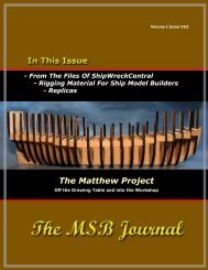
When the below diagram was sent to me, I nearly had a heart attack! It is a<br />
schematic that tried to correlate top timbers with floor timbers that was made at the<br />
Wasa museum in the 1980's using a few known locations of timbers. As you can see,<br />
it looks pretty messy with no real obvious pattern.<br />
Image Courtesy of Statens Maritima Museer<br />
and drawn by Eva Marie Stolt.<br />
The MSB Journal<br />
www.modelshipbuilder.com<br />
18
Fred Hocker of the Swedish National Maritime Museums and director of research at<br />
the Wasa museum, told me of the thesis on the framing of northern European ships<br />
that I mentioned before and also sent me an email that summed up the Wasa<br />
framing in a general way:<br />
"At a typical frame station, there is a floor timber that reaches the turn of the<br />
bilge on each side, a first futtock that reaches from the garboard to a little<br />
above the orlop, a second futtock from the head of the floor timber to about<br />
the level of the upper gundeck ports, and a toptimber from the upper limit of<br />
the lower gundeck to the rail.<br />
There are a few filling pieces used in the way of the gunports where it was<br />
necessary to cut frames. The ends of the first futtocks are very uneven, as<br />
are the upper ends of the second futtocks and the lower ends of the top<br />
timbers.<br />
In addition, the frames are not square to the keel, but are slightly skewed,<br />
and toward the ends of the ship they tend to lean inward, toward amidships.<br />
Because the framing is fitted to the planking, rather than the other way<br />
round, there was no need to make sure that the frames stood square to the<br />
keel and parallel to each other, only that they filled the space and had good<br />
overlaps between elements.<br />
There are no cant frames at the stern, and the bow is framed in the Dutch<br />
manner. Instead of cant frames, the floor timbers continue up the inner face<br />
of the stem, normal to the curve, with futtocks stepped on their forward<br />
faces.<br />
The hawse pieces, which are massive timbers over a meter in width, are<br />
butted against the uppermost floor timber, and there are a couple of framing<br />
elements parallel to them, filling the space between the hawse pieces and the<br />
forward most futtocks of the floor timbers."<br />
I also ran across the below picture that looked much like what he described. I sent it<br />
to him and he concurred with me that it looked very much like what is suspected to<br />
be underneath the planking of the real ship. So, I had visual and worded<br />
documentation that I could use to help me picture what my models framing was<br />
going to eventually look like.<br />
The MSB Journal<br />
www.modelshipbuilder.com<br />
19
With this, the answers to a couple more questions that I had, and the information<br />
presented in the thesis, I was confident that I could make an attempt at drawing a<br />
framing diagram that would show the general pattern of the Wasa's hull framing.<br />
I first noticed that my plans contained a sheer plan that showed the inside of the<br />
ship. It included locations of top timbers and floor timbers.<br />
It should be noted here that these plans presented in this practicum were last<br />
revised in the 1980's and that new plans and a series of volumes are coming out<br />
within the next few years. These new plans and books will be much more detailed<br />
and allow a person, if it is desired, to actually build an exact replica of the ship in full<br />
scale down to every hull timber and fastening. The old plans are good enough to<br />
build a model from, however.<br />
Image Courtesy of Statens Maritima Museer and drawn by Eva Marie Stolt.<br />
I was soon to find out that the locations of at least the floors did not line up in any<br />
form or fashion with the locations of the top timbers. Remember the first framing<br />
diagram that I showed This was done on the plan in order to approximate the nonlinear<br />
correlation between floor and top timbers.<br />
I was also aware, however, that the top timbers are exposed on the real ship since<br />
the inside of the upper part of the inside of the rail is not planked over.<br />
When you start drawing your framing diagram, you will need to take this kind of<br />
plan, if you have one, and tape it down to your light table. Over the top of the plan<br />
you will need to tape down a large piece of paper that is big enough to cover the<br />
entirety of the plan.<br />
If you don't have a cut away view of the inside of your ship, just lay down your sheer<br />
plan and put a large piece of paper on that.<br />
Then, trace things that are definite details such as the position of the keel, stem,<br />
sternpost, vertical positions of decks, and vertical and horizontal reference lines.<br />
From your research, or as in my case, from your plan, record or trace in any parts of<br />
the framing members that you can.<br />
The MSB Journal<br />
www.modelshipbuilder.com<br />
20
The picture below shows a close up of the forward part of my drawing with reference<br />
or station lines, keel, stem, vertical positions of decks, and tentative positions of<br />
floor and top timbers drawn in.<br />
You will also notice that I have a few frames drawn as well. Since the floor timbers<br />
and the top timbers didn't correlate in the plan and since the top timbers are<br />
exposed on the real ship, I put much more weight on the top timbers and didn't<br />
move them at all. Most of the floor timbers that you see drawn in eventually got<br />
erased.<br />
Notice that in the above picture and at each frame section, there is a floor timber<br />
going from the garboard to the turn of the bilge (the general vertical position of the<br />
turn was taken from the cross section drawings that will be shown later on), a first<br />
futtock that goes from the garboard to a little above the orlop deck, a second futtock<br />
that goes from the head of the floor timber, or runghead, to the level of the upper<br />
gundeck ports, and a top timber from the upper gundeck to the rail.<br />
This picture above was taken for the sole purpose of sending it in to Fred at the<br />
museum to see if I was on the right track.<br />
It turned out that I was a little off when it came to the top timbers. There should<br />
have been more overlap between the second futtocks and the top timbers. So I<br />
simply made them longer on their lower end. At any rate, however, I followed<br />
what Fred of the Wasa museum had told me.<br />
The MSB Journal<br />
www.modelshipbuilder.com<br />
21
The above diagram shows the completed framing diagram. Notice that I used the<br />
same rules that were explained to me throughout and it gave me a simplified,<br />
repeating framing pattern. I did send this picture in as well and learned that it could<br />
be improved further by redrawing the fashion piece (the last frame at the stern) in a<br />
different manner. Fred told me, however, that what I had drawn was a good<br />
representation of the framing to use in a model.<br />
Notice there are no cant frames as was Dutch practice of this time period like<br />
Fred from the Wasa museum stated. (The Swedes hired Dutch master shipbuilders to<br />
oversee the work on the Wasa) The frames also incline slightly toward the middle of<br />
the ship, especially at the stern. Notice also that the hull is solid wood due to framing<br />
member overlaps from the keel to a little above the turn of the bilge, and again from<br />
the lower ends of the top timbers to the underside of the weather deck. The tops and<br />
bottom of framing members are also very uneven.<br />
Known practices such as these on a ship of the size, period, and nationality that you<br />
are building are invaluable facts that you can use to come up with your framing<br />
diagram.<br />
In the next issue of The MSB Journal - Part II of Clayton Johnson’s “Frame Lofting<br />
Practicum” which will deal with drawing Frame Tracings.<br />
The MSB Journal<br />
www.modelshipbuilder.com<br />
22
From the Files of <strong>Ship</strong>WreckCentral<br />
Type: Aircraft Carrier<br />
Tonnage: Not specified<br />
Displacement: 21,000<br />
LOA: 741.3 ft<br />
Beamwidth: 80.7 ft<br />
Draws: 19.9 ft<br />
Nationality: American<br />
Era: 1920’s-40’s<br />
Year Built: 1936<br />
Place Built: Bethlehem Steel Corp.,<br />
Qunicy Mass.<br />
Year Launched: 1939<br />
Year Sunk: 15 September, 1942<br />
Place Sunk: 150 miles southeast of<br />
San Cristobal Island<br />
Cause of Sinking: Japanese<br />
submarine I-119<br />
Loss of life: 193<br />
Body of Water: Pacific Ocean<br />
Lattitude: S0010 036’<br />
Longitude: W 0880 017’<br />
The only vessel of her class built, the U.S. Navy's eighth Wasp was the last of the so-called<br />
"treaty carriers" whose size was limited by the Washington Naval Conference of 1922. Wasp<br />
entered service on the East Coast, and in July 1941, she ferried Army Air Force planes to Iceland<br />
when the United States occupied that country. The rest of the year she spent on the North<br />
Atlantic Neutrality Patrol between Newfoundland and the Caribbean. Following the U.S. entry into<br />
World War II, Wasp made two voyages from England to the western Mediterranean; from here<br />
she launched British Spitfire fighters for the relief of Malta. On June 6, 1942, she sailed from<br />
Norfolk for the Pacific in an effort to shore up the U.S. carrier fleet, weakened by the recent loss<br />
of USS Lexington and Yorktown. Joining a Support Force under Rear Admiral Frank Fletcher,<br />
Wasp supported the first Marine landings on Guadalcanal on August 7-8. On September 15,<br />
Hornet and Wasp (then the only operational U.S. carriers in the South Pacific) were again<br />
covering Marine transports headed for Guadalcanal.<br />
While refueling planes about 150 miles southeast of San Cristobal Island, Wasp was hit by two<br />
torpedoes from the Japanese submarine I-119. The resulting fires were uncontrollable, and<br />
Captain Forrest P. Sherman ordered the ship abandoned. She was then torpedoed and sunk by<br />
USS Landsdowne; 193 of Wasp's crew died.<br />
To learn more about shipwrecks and their location, visit www.shipwreckcentral.com.<br />
The MSB Journal<br />
www.modelshipbuilder.com<br />
23
Clubs & Organizations with a Web Presence<br />
Each month we’ll display a list of clubs and organizations from around the world which you may<br />
find useful in your modeling. You will find everything from general modeling clubs to websites<br />
where you can pursue research on projects you are working on. You can check at the MSB<br />
website for a more complete list (www.modelshipbuilder.com/resources/links.html).<br />
General Dutch <strong>Ship</strong> <strong>Model</strong>ers Association – www.ansf.nl<br />
The Great Schooner <strong>Model</strong> Society - www.pittelli.com/schooner<br />
Historical Navy <strong>Ship</strong>s Association - www.maritime.org/hnsa-intro.htm<br />
International Naval Research Organization – www.warship.org<br />
National Maritime Historical Society – www.seahistory.org<br />
Nautical Research Guild – www.naut-res-guild.org<br />
<strong>Model</strong> Yachting Association – Great Britain - www.radiosailing.org.uk<br />
U.S. Vintage <strong>Model</strong> Yacht Group (Sail) - www.swcp.com/usvmyg<br />
Don’t see a listing you know of or are looking for Let us know!<br />
(msbjournal@modelshipbuilder.com)<br />
Handy Tools in the Workshop<br />
Engineering Squares<br />
These extremely accurate squares can be of<br />
particular value in setting up workshop power<br />
equipment – table saws, jointers, or any machine<br />
that you require to make precision cuts.<br />
Machined to continental engineering standards<br />
(the code used is British Standard 939 Grade B –<br />
which means less than 0.001" deviation per inch<br />
over the entire length of the blade).<br />
Source: Lee Valley Tools<br />
The MSB Journal<br />
www.modelshipbuilder.com<br />
24
The MSB Journal Classifieds<br />
Have some modeling books, tools, kits that you want to sell Looking for a place to advertise<br />
them where other modelers will see them<br />
We are offering this section of The MSB Journal for fellow modelers to do just that. Simply send<br />
us the details of what you have for sale, the price, contact information etc and we’ll fit it into the<br />
next issue.<br />
The MSB Journal<br />
www.modelshipbuilder.com<br />
25
Nautical Entertainment<br />
Answers in the next Issue<br />
The MSB Journal<br />
www.modelshipbuilder.com<br />
26
Some Nautical Trivia & Fun<br />
The “plow” anchor was designed by Prof. G.I. Taylor of Cambridge University in<br />
England. He called it the “CQR”.<br />
What do the initials “CQR” stand for<br />
If you say the three initials fast, it will quickly become evident. For those who<br />
can’t…it means “Secure”<br />
What is a Nautical Hammerfer<br />
Why, driving nautical nails of course!<br />
Where did the term Scuttlebutt come from<br />
In the days of sail, fresh water was carried in casks or butts.<br />
To get the water it was necessary to break it open or scuttle<br />
it. To scuttle a butt was to open it for consumption. While<br />
taking this water break, the crew often passed ships gossip.<br />
Hence the term Scuttlebutt meaning idle talk or gossip. In the<br />
WWII era and sometime thereafter, drinking fountains aboard<br />
ship or on shore stations were often called Scuttlebutts.<br />
Why do Lighthouse Keepers keep chickens<br />
Duh! So they can have eggs with their beacon! LOL….I know…..I just couldn’t help myself!<br />
And finally….<br />
According to tradition, what would you expect to hear from the ship’s bell at midnight<br />
each New Years-Eve<br />
16 bells. Eight for the year just passed and Eight for the New Year to come. Each, rung<br />
respectively, by the oldest crew member and the youngest.<br />
The MSB Journal<br />
www.modelshipbuilder.com<br />
27