Axle or Sprocket Replacement - Model B - Concept2
Axle or Sprocket Replacement - Model B - Concept2
Axle or Sprocket Replacement - Model B - Concept2

You also want an ePaper? Increase the reach of your titles
YUMPU automatically turns print PDFs into web optimized ePapers that Google loves.
<strong>Axle</strong> <strong>or</strong> <strong>Sprocket</strong> <strong>Replacement</strong> - <strong>Model</strong> B<br />
BA/SR<br />
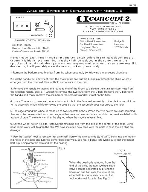
PARTS<br />
®<br />
MORRISVILLE, VERMONT USA<br />
WWW.CONCEPT2.COM<br />
E-MAIL:ROWING@CONCEPT2.COM<br />
FLYWHEEL COG TOOL SET - PN 484<br />
<strong>Axle</strong> Shaft - PN 248<br />
Flywheel Repair <strong>Sprocket</strong> Kit - PN 485<br />
Chain w/Connect<strong>or</strong> & Swivel - PN 280<br />
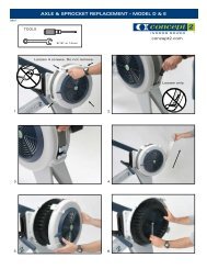
TOOLS NEEDED:<br />
Philips Head Screwdriver<br />
Flat Head Screwdriver<br />
Long Nose Pliers<br />
Pliers <strong>or</strong> Pipewrench<br />
Bridge Pin<br />
Hammer<br />
1/2” Wrench<br />
Note: Please read through these directions completely bef<strong>or</strong>e beginning replacement procedure.<br />
It is highly recommended that the chain be replaced at the same time as the<br />
sprockets. The old chain does get w<strong>or</strong>n and may not w<strong>or</strong>k at all on the new sprockets. If it<br />
does w<strong>or</strong>k, it will probably wear the new sprockets prematurely.<br />
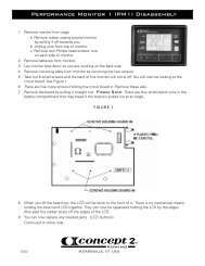
1. Remove the Perf<strong>or</strong>mance Monit<strong>or</strong> from the wheel assembly by following the enclosed directions.<br />
2. Pull the handle out a few feet from the chain guide and put the bridge pin through the chain where it<br />
emerges from the mon<strong>or</strong>ail. This will hold some slack in the chain.<br />
3. Remove the handle by tapping the rounded end of the U-bolt to dislodge the stainless steel nuts from<br />
the wooden handle. Use a ˚” wrench to remove the two nuts from the U-bolt. Remove the U-bolt from<br />
the handle and chain; remove the chain from the sprockets and let it rest on the flo<strong>or</strong>.<br />
4. Use a ˚” wrench to remove the four bolts which hold the flywheel assembly to the black arms. Hold on<br />
to the assembly wheel while removing the bolts so that the assembly does not drop to the flo<strong>or</strong>.<br />
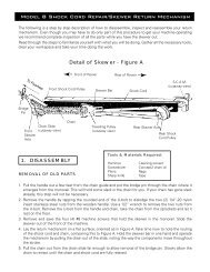
5. The cage around the wheel is made up of two separate halves. When the two halves are disassembled<br />
they must be reassembled with no change in their relative position. To accomplish this, mark each half with<br />
a piece of tape. The marks can then be aligned when the cage is reassembled.<br />
6. Lay the wheel flat on its side. Remove the retaining clip from the axle at the center of the cage. Long<br />
nose pliers w<strong>or</strong>k well to grab the clip. We have included new clips with the parts in case the old clips are<br />
damaged.<br />
7. Use the “puller” tool to remove first cage half. Screw the two outside (5/16”x1˚”) bolts into the mounting<br />
holes of the cage and turn the center bolt clockwise. See Fig. 1 below left. Make sure that the center<br />
bolt is pushing onto the axle and not the bearing.<br />
Wing Nut<br />
Nut-tightened against wing nut<br />
Carraige Bolt<br />
Fig. 1<br />
Fig. 2<br />
Flywheel Cage Half<br />
(2) 5/16” Bolts<br />
Puller Plate<br />
<strong>Axle</strong><br />
When the bearing is removed from the<br />
end of the axle, the two flywheel cage<br />
halves can be separated by prying the<br />
hooks on one half over the wire of the<br />
other half. A screwdriver <strong>or</strong> other flat<br />
tool w<strong>or</strong>ks well f<strong>or</strong> this. See Fig. 2.<br />
Flywheel Cage Hub
8. Remove “puller” from cage and set this half aside. The second half can be removed the same way.<br />
9. You now have a flywheel with an axle through it and two cage halves. This is a good time to clean everything.<br />
WD-40, <strong>or</strong> other solvents and a rag will remove any dust and/<strong>or</strong> oil from the wheel and the cage.<br />
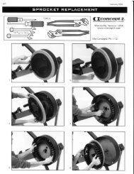
10. Remove the sprockets from the axle. The tool that looks<br />
like a large nut with a bearing inside it will hold the axle so<br />
the sprockets can be unscrewed. This tool should be placed<br />
onto the end of the axle opposite the sprockets. The writing<br />
on the bearing should be away from the wheel. The large nut<br />
can then be held with a wrench and the sprockets removed<br />
counterclockwise. A large pair of pliers <strong>or</strong> a pipe wrench may<br />
be needed depending on how severely the sprockets are<br />
w<strong>or</strong>n. See Fig. 3.<br />
^<br />
Fig. 3<br />
11. When putting on the new sprockets, the larger one must go on first<br />
with the hub of the sprocket toward the wheel. The smaller one can then<br />
go on. Both sprockets can be put on finger tight. They do not need to be<br />
tightened with a wrench. See Fig. 4.<br />
Fig. 4<br />
12. Gently lay the flywheel down on its side with the flat side<br />
of the wheel up. Take the open cage half (this is the one with<br />
the chain guide and wire f<strong>or</strong> the monit<strong>or</strong> on it) and start the<br />
bearing onto the end of the axle. The third and final tool is<br />
then used to push the bearing back onto the axle. One end of<br />
the tool is countersunk; this is the end to use toward the<br />
axle. Center the tool, countersunk end down, on the bearing<br />
at the center of the cage and gently tap the end with a<br />
hammer. When you feel the axle bottom out in the tool, stop<br />
tapping. The end of the axle will go into the countersink the<br />
c<strong>or</strong>rect distance so a clip can be inserted. See Fig. 5.<br />
^<br />
Fig. 5<br />
13. Turn the flywheel over and place the other cage half on the wheel. Align your marks on the two cage<br />
halves and rehook the halves using the same technique as in disassembly. See steps 8, 7 and 6. Tap this<br />
half onto the axle the same way as the first half. Double check your alignment marks on the cages and, if<br />
they are c<strong>or</strong>rect, put the new clips on both ends of the axle. The clips need to be in the grooves to hold<br />
securely.<br />
14. Attach the Perf<strong>or</strong>mance Monit<strong>or</strong> to the flywheel following the same page of instruction f<strong>or</strong> the disassembly.<br />
Mount the flywheel assembly to the two arms of the Indo<strong>or</strong> Rower.<br />
03/01