Outline of the Japanese Guidelines for Seismic Retrofitting of RC ...
Outline of the Japanese Guidelines for Seismic Retrofitting of RC ...
Outline of the Japanese Guidelines for Seismic Retrofitting of RC ...

You also want an ePaper? Increase the reach of your titles
YUMPU automatically turns print PDFs into web optimized ePapers that Google loves.
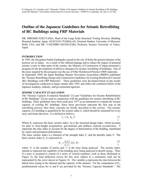
H. Fukuyama, J.G. Tumialan, and T. Matsuzaki, "<strong>Outline</strong> <strong>of</strong> <strong>the</strong> <strong>Japanese</strong> <strong>Guidelines</strong> <strong>for</strong> <strong>Seismic</strong> Retr<strong>of</strong>itting <strong>of</strong> <strong>RC</strong> Buildings<br />
using FRP Materials," Non-metallic rein<strong>for</strong>cement <strong>for</strong> Concrete Structures - FRP<strong>RC</strong>S-5, Cambridge, UK, July 16-18, 2001.<br />
<strong>Outline</strong> <strong>of</strong> <strong>the</strong> <strong>Japanese</strong> <strong>Guidelines</strong> <strong>for</strong> <strong>Seismic</strong> Retr<strong>of</strong>itting<br />
<strong>of</strong> <strong>RC</strong> Buildings using FRP Materials<br />
DR. HIROSHI FUKUYAMA, Head <strong>of</strong> <strong>the</strong> Large Scale Structural Testing Division, Building<br />
Research Institute, Japan, GUSTAVO TUMIALAN, Doctoral Student, University <strong>of</strong> Missouri-<br />
Rolla, USA, and DR. YASUHIRO MATSUZAKI, Pr<strong>of</strong>essor, Science University <strong>of</strong> Tokyo,<br />
Japan<br />
INTRODUCTION<br />
In 1995, <strong>the</strong> Hyogoken-Nanbu Earthquake caused to <strong>the</strong> city <strong>of</strong> Kobe <strong>the</strong> greatest disaster <strong>of</strong> <strong>the</strong><br />
postwar era in Japan. As a result <strong>of</strong> <strong>the</strong> inflicted damage and to reduce <strong>the</strong> impact <strong>of</strong> potential<br />
seismic events in o<strong>the</strong>r parts <strong>of</strong> <strong>the</strong> country, <strong>the</strong> Ministry <strong>of</strong> Construction <strong>of</strong> Japan promoted a<br />
program <strong>for</strong> <strong>the</strong> development <strong>of</strong> effective strategies <strong>for</strong> seismic retr<strong>of</strong>itting <strong>of</strong> buildings. One <strong>of</strong><br />
<strong>the</strong> areas targeted by this program was <strong>the</strong> use <strong>of</strong> Fiber Rein<strong>for</strong>ced Polymer (FRP) materials.<br />
In September 1999, <strong>the</strong> Japan Building Disaster Prevention Association (JBDPA) published<br />
<strong>the</strong> “<strong>Seismic</strong> Retr<strong>of</strong>itting Design and Construction <strong>Guidelines</strong> <strong>for</strong> Existing Rein<strong>for</strong>ced Concrete<br />
(<strong>RC</strong>) Buildings with FRP Materials”. These guidelines were developed based on <strong>the</strong> results<br />
<strong>of</strong> investigations conducted in Japan, mainly after 1995, and reflect <strong>the</strong> combined ef<strong>for</strong>ts <strong>of</strong> <strong>the</strong><br />
<strong>Japanese</strong> academy, industry, and governmental agencies.<br />
SEISMIC CAPACITY EVALUATION<br />
The “<strong>Seismic</strong> Capacity Evaluation Standards” [1] and “<strong>Guidelines</strong> <strong>for</strong> <strong>Seismic</strong> Rehabilitation<br />
<strong>of</strong> <strong>RC</strong> Buildings” [2] are used in conjunction with <strong>the</strong> guidelines <strong>for</strong> seismic retr<strong>of</strong>itting <strong>of</strong> <strong>RC</strong><br />
buildings. These guidelines have been used since 1977 as an instrument to evaluate <strong>the</strong> seismic<br />
capacity <strong>of</strong> existing <strong>RC</strong> buildings. Since <strong>the</strong>se provisions represent <strong>the</strong> first step in <strong>the</strong><br />
retr<strong>of</strong>itting process, <strong>the</strong>ir basic concepts are briefly described in this section. The seismic<br />
capacity <strong>of</strong> a building is quantified by <strong>the</strong> seismic index I s , which should be estimated <strong>for</strong> every<br />
story and frame direction. It is defined as follows:<br />
Is = Eo<br />
SD<br />
T<br />
(1<br />
)<br />
Where E o expresses <strong>the</strong> basic seismic index, S D is <strong>the</strong> structural design index, which accounts<br />
<strong>for</strong> plan or story-height irregularities, gravitational and stiffness centroid eccentricities. T<br />
represents <strong>the</strong> time index to account <strong>for</strong> <strong>the</strong> degree <strong>of</strong> deterioration <strong>of</strong> <strong>the</strong> building, manifested<br />
by cracks and permanent de<strong>for</strong>mations.<br />
The basic seismic index is a function <strong>of</strong> <strong>the</strong> strength index C, and <strong>the</strong> ductility index F. The<br />
basic seismic index E o is expressed as:<br />
n + 1<br />
(2<br />
E o<br />
= f (C, F)<br />
n + i<br />
)<br />
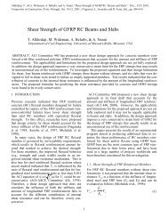
where ‘n’ is <strong>the</strong> number <strong>of</strong> stories and ‘i’ is <strong>the</strong> story being analyzed. The seismic index<br />
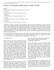
intends to represent <strong>the</strong> capability <strong>of</strong> <strong>the</strong> building story being analyzed to absorb energy. Thus,<br />
if a story is assumed to consist <strong>of</strong> a series <strong>of</strong> vertical members, such as those illustrated in<br />
Figure 1a, <strong>the</strong> load deflection curves <strong>for</strong> this story subject to a monotonic load can be<br />
represented by <strong>the</strong> curve shown in Figures 1b. The variable α represents <strong>the</strong> ratio between <strong>the</strong><br />
lateral <strong>for</strong>ce acting in <strong>the</strong> element and <strong>the</strong> capacity <strong>of</strong> <strong>the</strong> element. For <strong>the</strong> computation <strong>of</strong> E o ,<br />
predetermined values <strong>for</strong> α and F are provided by <strong>the</strong> “<strong>Seismic</strong> Capacity Standards”. The<br />
1
H. Fukuyama, J.G. Tumialan, and T. Matsuzaki, "<strong>Outline</strong> <strong>of</strong> <strong>the</strong> <strong>Japanese</strong> <strong>Guidelines</strong> <strong>for</strong> <strong>Seismic</strong> Retr<strong>of</strong>itting <strong>of</strong> <strong>RC</strong> Buildings<br />
using FRP Materials," Non-metallic rein<strong>for</strong>cement <strong>for</strong> Concrete Structures - FRP<strong>RC</strong>S-5, Cambridge, UK, July 16-18, 2001.<br />
largest value obtained by using <strong>the</strong> equations illustrated in Figure 1c and 1d is used <strong>for</strong> <strong>the</strong><br />
computation <strong>of</strong> I s .<br />
(1) Short Column (2) Wall Element (3) Ductile Column<br />
(a) Idealized Building Story<br />
(b) Ideal Load vs. Displacement Curves<br />
Streng<strong>the</strong>ning Index (C)<br />
C1<br />
a 2C2<br />
o<br />
Brittle Behavior<br />
E = (C + α C + α C ) F<br />
C2<br />
1<br />
2<br />
2<br />
3<br />
3<br />
1<br />
Streng<strong>the</strong>ning Index (C)<br />
C 1<br />
a 2C2<br />
a 3C3<br />
Ductile Behavior<br />
E +<br />
2<br />
2<br />
2<br />
= (C F ) + (C F ) (C F )<br />
O 1 1 2 2 3 3<br />
C2<br />
a 1C 3<br />
C 3<br />
a 3C3<br />
a 1C3<br />
C3<br />
F1 F 2 F3<br />
F1 F 2 F3<br />
Ductility Index (F)<br />
Ductility Index (F)<br />
(c) Brittle Behavior<br />
(d) Ductile Behavior<br />
Figure 1. <strong>Seismic</strong> Capacity Evaluation<br />
Three procedures are recommended to estimate I s , which are dependable on <strong>the</strong> characteristics<br />
<strong>of</strong> <strong>the</strong> story to be analyzed. These procedures can be described as:<br />
• The first procedure is <strong>the</strong> simplest, which is used <strong>for</strong> stories with a large density <strong>of</strong><br />
walls. The ultimate strength is estimated based on <strong>the</strong> concrete shear strength and cross<br />
section area <strong>of</strong> columns and walls.<br />
• The second procedure requires <strong>the</strong> calculation <strong>of</strong> <strong>the</strong> ultimate capacity and ductility <strong>of</strong><br />
columns and walls. The beams are usually assumed to be rigid. This procedure is used<br />
<strong>for</strong> “weak column-strong beam” frames.<br />
• The third procedure implies to calculate <strong>the</strong> ultimate capacity and ductility <strong>of</strong> <strong>the</strong><br />
vertical members as well as beams. All <strong>the</strong> possible mechanisms <strong>of</strong> failure are taken<br />
into account.<br />
Once <strong>the</strong> seismic index I s is estimated, this value is compared to a limit index I so . If <strong>the</strong> I s<br />
index is larger than <strong>the</strong> limit index, <strong>the</strong> building is expected to have a good per<strong>for</strong>mance during<br />
a seismic event. O<strong>the</strong>rwise, <strong>the</strong> structures must be retr<strong>of</strong>itted to comply with <strong>the</strong> requirements<br />
<strong>of</strong> current building standards. Evaluations conducted on damaged buildings due to earthquakes<br />
indicated that whenever <strong>the</strong> I s indices were less than 0.3 severe damage was observed. Also,<br />
when <strong>the</strong> values <strong>of</strong> <strong>the</strong> I s indices were larger than 0.6, <strong>the</strong> damage observed in <strong>the</strong> buildings<br />
was moderate. This was evident from <strong>the</strong> evaluations per<strong>for</strong>med to <strong>the</strong> building structures after<br />
<strong>the</strong> Hyogoken-Nanbu Earthquake in 1995, where a value <strong>of</strong> 0.6 indicated <strong>the</strong> border limit<br />
between severe and moderate damage. Thereby, <strong>the</strong> “Standards <strong>for</strong> <strong>Seismic</strong> Capacity<br />
Evaluation <strong>of</strong> <strong>RC</strong> Buildings” specify a value equal to 0.6 as limit index I so to prevent collapse<br />
or severe damage.<br />
2
H. Fukuyama, J.G. Tumialan, and T. Matsuzaki, "<strong>Outline</strong> <strong>of</strong> <strong>the</strong> <strong>Japanese</strong> <strong>Guidelines</strong> <strong>for</strong> <strong>Seismic</strong> Retr<strong>of</strong>itting <strong>of</strong> <strong>RC</strong> Buildings<br />
using FRP Materials," Non-metallic rein<strong>for</strong>cement <strong>for</strong> Concrete Structures - FRP<strong>RC</strong>S-5, Cambridge, UK, July 16-18, 2001.<br />
When <strong>the</strong> structures is found to be structurally deficient, new values <strong>for</strong> C and/or F have to be<br />
estimated to meet <strong>the</strong> structural demand.<br />
SCOPE OF THE JBDPA GUIDELINES FOR STRENGTHENING WITH FRP<br />
The <strong>Japanese</strong> guidelines <strong>for</strong> seismic retr<strong>of</strong>itting <strong>of</strong> <strong>RC</strong> building structures [3] provide<br />
specifications on <strong>the</strong> characteristics <strong>of</strong> <strong>the</strong> FRP materials commonly used in Japan, <strong>the</strong>ir proper<br />
handling and installation. Also, pertaining design and detailing recommendations are<br />
provided, which mainly target <strong>the</strong> shear streng<strong>the</strong>ning <strong>of</strong> ei<strong>the</strong>r columns or beams. Some <strong>of</strong> <strong>the</strong><br />
main provisions are described in <strong>the</strong> subsequent sections. The guidelines are part <strong>of</strong> <strong>the</strong><br />
“<strong>Guidelines</strong> <strong>for</strong> <strong>Seismic</strong> Rehabilitation <strong>of</strong> <strong>RC</strong> Buildings”, a comprehensive publication that<br />
documents different retr<strong>of</strong>itting methods utilized in Japan.<br />
MATERIALS<br />
The JBDPA guidelines describe <strong>the</strong> properties <strong>of</strong> PAN-class high-strength carbon fiber sheets,<br />
and aramid fiber sheets. In its turn, aramid is sub-classified as aramid 1 (homopolymer) and<br />
aramid 2 (copolymer). Carbon fiber sheets are labeled based on <strong>the</strong> tensile strength <strong>of</strong> <strong>the</strong><br />
fiber; whereas, <strong>the</strong> denomination <strong>of</strong> <strong>the</strong> aramid fiber sheets is based on <strong>the</strong> tensile strength in a<br />
width <strong>of</strong> one meter. The values <strong>of</strong> tensile strength and modulus <strong>of</strong> elasticity have been<br />
estimated from laminates made <strong>of</strong> carbon or aramid fibers bound in a resin matrix. Table 1<br />
presents <strong>the</strong> properties <strong>of</strong> fibers bound by epoxy or methacrylate resin.<br />
Table 1. Properties <strong>of</strong> FRP Sheets<br />
Carbon Fiber<br />
Aramid Fiber<br />
Characteristic<br />
3400 MPa Class 2900 MPa Class Aramid 1 Aramid 2<br />
Type <strong>of</strong> Fiber PAN-class High-Strength Homopolymer Copolymer<br />
Tensile Strength ≥ 3400 MPa ≥ 2900 MPa ≥ 2060 MPa ≥ 2350 Mpa<br />
+<br />
Young’s Modulus<br />
230 45<br />
− 15GPa<br />
118 ± 20GPa<br />
78 ± 15GPa<br />
Fiber Density 1 .80 ± 0. 05<br />
1 .45 ± 0. 05 1 .39 ± 0. 05<br />
The efficiency <strong>of</strong> <strong>the</strong> streng<strong>the</strong>ning work is influenced by <strong>the</strong> viscosity <strong>of</strong> <strong>the</strong> adhesive resins.<br />
Thus, if sagging is likely to occur, a resin <strong>of</strong> higher viscosity is recommended. Also, if smooth<br />
impregnation in <strong>the</strong> fiber is required, a resin with lower viscosity should be used. In <strong>the</strong> case<br />
<strong>of</strong> primers, epoxy and methacrylate resin are commonly used. Due to potential alterations <strong>of</strong><br />
<strong>the</strong> hardening process, it is not allowed to use an epoxy-based primer in combination with a<br />
methacrylate-based adhesive or vice versa. In similar way, if <strong>the</strong> putty material is not<br />
compatible with <strong>the</strong> adhesive and primer resins, imperfect adhesion may occur.<br />
DESIGN APPROACHES FOR STRENGTHENING OF COLUMNS AND BEAMS<br />
In order to determine <strong>the</strong> required amount <strong>of</strong> FRP streng<strong>the</strong>ning, <strong>the</strong> <strong>Japanese</strong> guidelines<br />
provide expressions to calculate <strong>the</strong> flexural and shear strengths, and ductility index <strong>of</strong> <strong>RC</strong><br />
members. The equations are based on those presented by <strong>the</strong> “Standards <strong>for</strong> <strong>Seismic</strong> Capacity<br />
Evaluation” and <strong>the</strong> “<strong>Guidelines</strong> <strong>for</strong> <strong>Seismic</strong> Rehabilitation <strong>of</strong> <strong>RC</strong> Buildings”. These equations<br />
were developed by Arakawa and Hirosawa, and have been widely used <strong>for</strong> <strong>the</strong> design <strong>of</strong> new<br />
construction. Initially, Arakawa developed expressions to calculate <strong>the</strong> structural capacities <strong>of</strong><br />
<strong>RC</strong> beams. Hirosawa modified those equations to make <strong>the</strong>m suitable to be applied in <strong>the</strong><br />
analysis <strong>of</strong> axially loaded members. The definitions <strong>of</strong> <strong>the</strong> variables used hereafter are<br />
presented at <strong>the</strong> end <strong>of</strong> this section.<br />
3
H. Fukuyama, J.G. Tumialan, and T. Matsuzaki, "<strong>Outline</strong> <strong>of</strong> <strong>the</strong> <strong>Japanese</strong> <strong>Guidelines</strong> <strong>for</strong> <strong>Seismic</strong> Retr<strong>of</strong>itting <strong>of</strong> <strong>RC</strong> Buildings<br />
using FRP Materials," Non-metallic rein<strong>for</strong>cement <strong>for</strong> Concrete Structures - FRP<strong>RC</strong>S-5, Cambridge, UK, July 16-18, 2001.<br />
Streng<strong>the</strong>ning <strong>of</strong> Columns<br />
Ultimate Flexural Capacity<br />
The ultimate flexural capacity <strong>of</strong> a <strong>RC</strong> column is calculated from <strong>the</strong> following expressions,<br />
which are originally included in <strong>the</strong> “Structural Regulations <strong>of</strong> Buildings” (Building Center <strong>of</strong><br />
Japan, 1997), a guide <strong>for</strong> structural design <strong>of</strong> new buildings, which must comply with <strong>the</strong><br />
“<strong>Japanese</strong> Building Standard Law”.<br />
For N max<br />
≥ N > N b<br />
:<br />
2<br />
⎛ N max − N<br />
[ ]<br />
⎟ ⎞<br />
0.5a σ + + −<br />
⎜<br />
g yg1D<br />
0.024(1 g1<br />
)(3.6 g1)bD<br />
Fc<br />
N max− N b ⎠<br />
(3a<br />
M<br />
u<br />
=<br />
(N-mm)<br />
⎝<br />
)<br />
For N ≥ b<br />
N ≥ 0: ⎛ N ⎞<br />
(3b<br />
M u = 05 . a gσ yg1D + 05 . ND⎜1<br />
− ⎟ (N-mm)<br />
⎝ bDFc<br />
⎠<br />
)<br />
For 0 > N ≥ N min :<br />
M<br />
u<br />
= 05 . agσ yg1D + 05 . Ng1D<br />
(N-mm) (3c<br />
)<br />
N b , N max and N min can be computed from:<br />
Balanced Axial Force: N<br />
b<br />
= 022 . ( 1+<br />
g1) bDFc<br />
(N) (4a)<br />
Ultimate Axial Force in Compression: N<br />
max<br />
= bDFc + a<br />
gσ y<br />
(N) (4b<br />
)<br />
Ultimate Axial Force in Tension: N min<br />
= −a g<br />
σ y<br />
(N) (4c)<br />
The shear <strong>for</strong>ce associated to <strong>the</strong> flexural capacity M u can be computed as:<br />
αM<br />
u<br />
Qmu<br />
= (N) (5)<br />
h<br />
o<br />
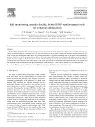
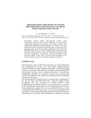
A α value equal to two may be used to estimate <strong>the</strong> shear arm. Figure 2 shows <strong>the</strong> agreement<br />
between <strong>the</strong> experimental and predicted values when using <strong>the</strong> previous equations.<br />
800<br />
Experimental Flexural Strength (kN)<br />
600<br />
400<br />
200<br />
0<br />
CFRP<br />
AFRP<br />
Steel Plate<br />
<strong>RC</strong><br />
0 200 400 600 800<br />
Expected Flexural Strength (kN)<br />
Figure 2. Validation <strong>of</strong> <strong>the</strong> Equation <strong>for</strong> Flexural Strength <strong>of</strong> Columns<br />
Ultimate Shear Capacity<br />
The equation used to quantify <strong>the</strong> shear capacity <strong>of</strong> an <strong>RC</strong> member streng<strong>the</strong>ned with FRP<br />
composite systems is also similar to that provided by <strong>the</strong> “Structural Regulations <strong>of</strong> Building”<br />
4
H. Fukuyama, J.G. Tumialan, and T. Matsuzaki, "<strong>Outline</strong> <strong>of</strong> <strong>the</strong> <strong>Japanese</strong> <strong>Guidelines</strong> <strong>for</strong> <strong>Seismic</strong> Retr<strong>of</strong>itting <strong>of</strong> <strong>RC</strong> Buildings<br />
using FRP Materials," Non-metallic rein<strong>for</strong>cement <strong>for</strong> Concrete Structures - FRP<strong>RC</strong>S-5, Cambridge, UK, July 16-18, 2001.<br />
(Building Center <strong>of</strong> Japan, 1997). The only modification is <strong>the</strong> addition <strong>of</strong> <strong>the</strong> product p wf σ fd to<br />
<strong>the</strong> summation Σp w σ wy , which intends to take into account <strong>the</strong> contribution <strong>of</strong> <strong>the</strong> FRP<br />
rein<strong>for</strong>cement. Thus:<br />
0.23<br />
⎡0.053pt<br />
(17.6 + F )<br />
⎤<br />
c<br />
(6a<br />
Qsu<br />
= ⎢<br />
+ 0.845 ∑ p<br />
wσwy<br />
+ 0.1σ<br />
o⎥bj<br />
(N)<br />
⎣ M/ Qd + 0.12<br />
⎦<br />
)<br />
where:<br />
∑ p σ w wy<br />
= p σ ws wys<br />
+ p σ wf fd<br />
≤ 10 MPa<br />
(6b<br />
)<br />
An upper limit <strong>of</strong> 10 MPa is imposed to Σp w σ wy based on <strong>the</strong> fact that a larger amount <strong>of</strong><br />
streng<strong>the</strong>ning would not significantly increase <strong>the</strong> shear capacity <strong>of</strong> <strong>the</strong> streng<strong>the</strong>ned member.<br />
Equation 6a can also be applied to predict <strong>the</strong> ultimate capacity <strong>of</strong> columns failing by bond<br />
splitting, and columns having longitudinal round rein<strong>for</strong>cing bars.<br />
Ano<strong>the</strong>r consideration to mention is that <strong>the</strong> value <strong>of</strong> <strong>the</strong> shear span-to-depth ratio expressed as<br />
M/Qd must not be less than one nor larger than three. The tensile strength <strong>of</strong> FRP <strong>for</strong> shear<br />
design is estimated as: σ fd = min{ E fd ε fd ,2/ 3σ<br />
f }<br />
The value <strong>of</strong> ε fd equal to 0.7% is adopted based on previous investigations, which have shown<br />
that <strong>the</strong> measured strain in <strong>the</strong> FRP laminate at <strong>the</strong> final stage, was between 0.5% and 1.5%.<br />
These investigations have also shown that specimens streng<strong>the</strong>ned with a large amount <strong>of</strong><br />
external rein<strong>for</strong>cement (p wf E fd ) possessed smaller strains at failure. Along with <strong>the</strong> first<br />
consideration, to avoid <strong>the</strong> rupture <strong>of</strong> <strong>the</strong> FRP laminate, a value <strong>of</strong> two-thirds <strong>of</strong> <strong>the</strong> tensile<br />
strength <strong>of</strong> <strong>the</strong> FRP laminate was adopted as a margin <strong>of</strong> safety, when designing <strong>for</strong> shear.<br />
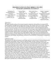
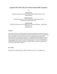
Figure 2 illustrates a good agreement between experimental and predicted values <strong>for</strong> shear<br />
strength <strong>of</strong> <strong>RC</strong> members streng<strong>the</strong>ned with FRP material when shear failure (rupture <strong>of</strong> <strong>the</strong><br />
laminate or compression failure <strong>of</strong> <strong>the</strong> concrete strut) and bond splitting are observed.<br />
Experimental Shear Strength(kN )<br />
600<br />
500<br />
400<br />
300<br />
200<br />
100<br />
0<br />
CFRP<br />
AFRP<br />
Steel Plate<br />
<strong>RC</strong><br />
0 100 200 300 400 500 600<br />
Expected Shear Strength(kN)<br />
(a) Shear Failure<br />
(b) Bond Splitting Failure<br />
Figure 2. Validation <strong>of</strong> <strong>the</strong> Equation <strong>for</strong> Shear Strength <strong>of</strong> Columns<br />
Ductility Factors and Ductility Index<br />
The ductility index F is a function <strong>of</strong> <strong>the</strong> ductility factor µ, and can be expressed by <strong>the</strong><br />
following relationships obtained from a degrading tri-linear hysteresis model.<br />
F = φ 2µ<br />
−1<br />
(7a)<br />
where:<br />
Experimental Shear Strength(kN )<br />
600<br />
500<br />
400<br />
300<br />
200<br />
100<br />
0<br />
CFRP<br />
Steel Plate<br />
<strong>RC</strong><br />
0 100 200 300 400 500 600<br />
Expected Shear Strength(kN)<br />
5
H. Fukuyama, J.G. Tumialan, and T. Matsuzaki, "<strong>Outline</strong> <strong>of</strong> <strong>the</strong> <strong>Japanese</strong> <strong>Guidelines</strong> <strong>for</strong> <strong>Seismic</strong> Retr<strong>of</strong>itting <strong>of</strong> <strong>RC</strong> Buildings<br />
using FRP Materials," Non-metallic rein<strong>for</strong>cement <strong>for</strong> Concrete Structures - FRP<strong>RC</strong>S-5, Cambridge, UK, July 16-18, 2001.<br />
1<br />
φ =<br />
(7b)<br />
0.75(1 + 0.05µ<br />
)<br />
The ultimate ductility factor µ <strong>of</strong> columns streng<strong>the</strong>ned with FRP materials is expressed as <strong>the</strong><br />
margin ratio <strong>of</strong> <strong>the</strong> shear strength to <strong>the</strong> shear <strong>for</strong>ce associated to <strong>the</strong> flexural strength. This<br />
factor can be calculated as follows:<br />
⎛ Q ⎞<br />
su<br />
µ = 10⎜<br />
− 0. 9⎟ , where 1≤<br />
µ ≤ 5<br />
(8)<br />
⎝ Q mu ⎠<br />
It is known that <strong>the</strong> ultimate shear strength increases when <strong>the</strong> axial <strong>for</strong>ce in <strong>the</strong> column is<br />
increased. Also, <strong>the</strong> ultimate flexural strength decreases when <strong>the</strong> axial <strong>for</strong>ce is larger than <strong>the</strong><br />
balanced axial <strong>for</strong>ce. This will cause that <strong>the</strong> associated shear <strong>for</strong>ce Q mu decreases, leading to<br />
a larger value <strong>of</strong> ultimate ductility factor µ. Thereby, to avoid <strong>the</strong> use <strong>of</strong> larger ductility<br />
values, <strong>the</strong> code specifies to calculate Q mu based on <strong>the</strong> balanced moment, whenever <strong>the</strong> axial<br />
<strong>for</strong>ce exceeds <strong>the</strong> balanced axial <strong>for</strong>ce.<br />
Streng<strong>the</strong>ning <strong>of</strong> Beams<br />
Ultimate Flexural Capacity<br />
The ultimate flexural capacity <strong>of</strong> <strong>RC</strong> beams is computed by using <strong>the</strong> following equation:<br />
M = 0.9a σ d (N-mm) (9)<br />
u<br />
t<br />
y<br />
The flexural capacity may also be calculated with equation 3b considering a value <strong>of</strong> axial<br />
<strong>for</strong>ce equal to zero. The equations provided <strong>for</strong> <strong>the</strong> guidelines are <strong>for</strong> streng<strong>the</strong>ning rectangular<br />
<strong>RC</strong> beams; <strong>the</strong> influence <strong>of</strong> <strong>the</strong> rein<strong>for</strong>cement <strong>of</strong> slabs is not considered. The shear <strong>for</strong>ce<br />
associated to <strong>the</strong> flexural capacity M u is calculated as:<br />
αMu<br />
Qmu<br />
= (N) (10)<br />
L<br />
o<br />
Ultimate Shear Capacity<br />
To estimate <strong>the</strong> ultimate shear capacity <strong>of</strong> <strong>RC</strong> beams streng<strong>the</strong>ned, <strong>the</strong> term representing <strong>the</strong><br />
influence <strong>of</strong> <strong>the</strong> axial <strong>for</strong>ce in equation 6a is dropped, thus:<br />
0.23<br />
⎡0.053pt<br />
(17.6 + F )<br />
⎤<br />
c<br />
Qsu<br />
= ⎢<br />
+ 0.845 ∑ pwσwy<br />
⎥bj<br />
(N) (12)<br />
⎣ M/ Qd + 0.12<br />
⎦<br />
Similarly to <strong>the</strong> case <strong>of</strong> columns, <strong>the</strong> value <strong>of</strong> <strong>the</strong> shear span-to-depth ratio expressed as M/Qd<br />
must not be less than one nor larger than three. In addition <strong>the</strong> term Σp w σ wy must satisfy <strong>the</strong><br />
relationship given by equation 6b.<br />
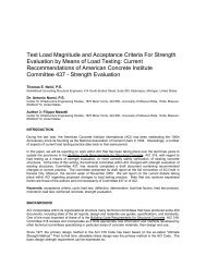
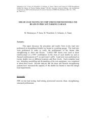
Figure 4 compares <strong>the</strong> experimental and predicted values <strong>for</strong> <strong>the</strong> maximum strength <strong>of</strong> <strong>RC</strong><br />
beams streng<strong>the</strong>ned in shear with FRP materials. It is observed that <strong>the</strong> calculated values by<br />
using equation 10 are on <strong>the</strong> safe side.<br />
Experimental Shear Strength/Q mu<br />
1.5<br />
1.0<br />
0.5<br />
CFRP<br />
AFRP<br />
<strong>RC</strong><br />
0<br />
0 0.5 1.0 1.5<br />
Expected Shear Strength(Q su )/Q mu<br />
6
H. Fukuyama, J.G. Tumialan, and T. Matsuzaki, "<strong>Outline</strong> <strong>of</strong> <strong>the</strong> <strong>Japanese</strong> <strong>Guidelines</strong> <strong>for</strong> <strong>Seismic</strong> Retr<strong>of</strong>itting <strong>of</strong> <strong>RC</strong> Buildings<br />
using FRP Materials," Non-metallic rein<strong>for</strong>cement <strong>for</strong> Concrete Structures - FRP<strong>RC</strong>S-5, Cambridge, UK, July 16-18, 2001.<br />
Figure 4. Validation <strong>of</strong> <strong>the</strong> Equation <strong>for</strong> Shear Strength <strong>of</strong> Beams<br />
Notation<br />
a g : Overall area <strong>of</strong> <strong>the</strong> longitudinal rein<strong>for</strong>cement <strong>of</strong> <strong>the</strong> column (mm 2 )<br />
a t : Area <strong>of</strong> <strong>the</strong> rein<strong>for</strong>cement in tension <strong>of</strong> a column or beam (mm 2 )<br />
a v : Area <strong>of</strong> shear rein<strong>for</strong>cement within a distance equal to <strong>the</strong> spacing “s” (mm 2 )<br />
B, D : Dimensions <strong>of</strong> <strong>the</strong> columns ( D ≥ b)<br />
(mm)<br />
D : Effective depth (mm)<br />
E fd : Modulus <strong>of</strong> elasticity <strong>of</strong> <strong>the</strong> FRP (Mpa)<br />
F : Ductility Index<br />
F c : Compressive strength <strong>of</strong> concrete (Mpa)<br />
g 1 : Ratio <strong>of</strong> distance between <strong>the</strong> centers <strong>of</strong> longitudinal rein<strong>for</strong>cement in tension and<br />
compression to <strong>the</strong> column width.<br />
h o : Clear height <strong>of</strong> column<br />
j : Distance between <strong>the</strong> tensile and compressive <strong>for</strong>ce resultants.<br />
(In columns: j = 0.80D. In beams: j = 7 / 8 d)<br />
M u : Ultimate Flexural Capacity (N-mm)<br />
M/Q : Shear span (mm). A value equal to half <strong>of</strong> <strong>the</strong> column height can be used<br />
N : Axial Force in <strong>the</strong> Column (N)<br />
p t : Ratio <strong>of</strong> tensile rein<strong>for</strong>cement = a t /bd (%)<br />
p ws : Ratio <strong>of</strong> existing shear steel rein<strong>for</strong>cement to area <strong>of</strong> contact surface = a v /bd (%)<br />
p wf : Ratio <strong>of</strong> FRP rein<strong>for</strong>cement to area <strong>of</strong> contact surface = Area FRP/bD (%)<br />
Q mu : Shear <strong>for</strong>ce associated to <strong>the</strong> ultimate flexural capacity (N)<br />
Q su : Ultimate Shear Capacity (N)<br />
ε fd<br />
: Effective Strain <strong>of</strong> <strong>the</strong> FRP, taken as 0.7%<br />
µ : Ultimate ductility factor<br />
σ y<br />
: Specified yielding strength <strong>of</strong> <strong>the</strong> longitudinal rein<strong>for</strong>cement (MPa)<br />
For round steel bars: f y = 295 MPa<br />
For de<strong>for</strong>med steel bars: f y = specified strength + 49 (MPa)<br />
σ wys<br />
: Specified yield strength <strong>of</strong> <strong>the</strong> existing transversal rein<strong>for</strong>cement (MPa)<br />
σ fd<br />
: Tensile strength <strong>of</strong> FRP <strong>for</strong> shear design (MPa)<br />
σ f<br />
: Tensile Strength <strong>of</strong> FRP (MPa)<br />
σ o<br />
: Axial stress (MPa), no larger than 7.84 Mpa<br />
SPECIAL PROVISIONS<br />
Streng<strong>the</strong>ning Without Removal <strong>of</strong> Mortar Finishing<br />
An advantage <strong>of</strong> using FRP materials <strong>for</strong> streng<strong>the</strong>ning <strong>RC</strong> elements is that <strong>the</strong> disruption to <strong>the</strong><br />
building occupants or o<strong>the</strong>r individuals in <strong>the</strong> nearby area is minimum. One source <strong>of</strong><br />
disruption is that caused by noise, dust and vibration when removing <strong>the</strong> finishing mortar.<br />
Surfaces finished with mortar were very common in Japan up to <strong>the</strong> mid-1970s, when <strong>the</strong> need<br />
<strong>for</strong> mortar finishing was basically eliminated with <strong>the</strong> improvement <strong>the</strong> <strong>for</strong>mworks. As a<br />
principle, <strong>the</strong> <strong>Japanese</strong> guidelines require <strong>the</strong> removal <strong>of</strong> finishing mortar <strong>for</strong> streng<strong>the</strong>ning <strong>of</strong><br />
columns. However, <strong>the</strong> guidelines present special specifications <strong>for</strong> <strong>the</strong> streng<strong>the</strong>ning <strong>of</strong> <strong>RC</strong><br />
rectangular columns without removing <strong>the</strong> finishing mortar, which can be carried out when<br />
appropriate control during <strong>the</strong> execution <strong>of</strong> <strong>the</strong> streng<strong>the</strong>ning work is provided. These<br />
specifications are based on previous experimental programs, which demonstrated that <strong>the</strong> shear<br />
capacity and ductility are not reduced when columns are wrapped around with FRP materials<br />
with <strong>the</strong> presence <strong>of</strong> finishing mortar. In addition, based on those researches, in order <strong>the</strong><br />
7
H. Fukuyama, J.G. Tumialan, and T. Matsuzaki, "<strong>Outline</strong> <strong>of</strong> <strong>the</strong> <strong>Japanese</strong> <strong>Guidelines</strong> <strong>for</strong> <strong>Seismic</strong> Retr<strong>of</strong>itting <strong>of</strong> <strong>RC</strong> Buildings<br />
using FRP Materials," Non-metallic rein<strong>for</strong>cement <strong>for</strong> Concrete Structures - FRP<strong>RC</strong>S-5, Cambridge, UK, July 16-18, 2001.<br />
streng<strong>the</strong>ning to be effective, any existing cracks on <strong>the</strong> finishing mortar have to be repaired<br />
prior to installing <strong>the</strong> FRP system.<br />
It is also specified that surfaces <strong>of</strong> mortar finishing painted with layers <strong>of</strong> thick painting<br />
materials may remain. The bond strength <strong>of</strong> <strong>the</strong>se materials must be at least 1 MPa; in addition,<br />
<strong>the</strong>y must not have any adverse chemical reaction with <strong>the</strong> epoxy adhesives. It is not<br />
recommended to attach FRP materials to surfaces constituted <strong>of</strong> plastering, finishing tiles,<br />
wallpaper, etc.<br />
The survey <strong>of</strong> <strong>the</strong> conditions <strong>of</strong> <strong>the</strong> finishing mortar should be based on <strong>the</strong> number <strong>of</strong> years <strong>of</strong><br />
service <strong>of</strong> <strong>the</strong> structure, <strong>the</strong> surface conditions, history <strong>of</strong> previous repair works and<br />
characteristics <strong>of</strong> finishing mortar. The strength <strong>of</strong> <strong>the</strong> mortar is estimated by means <strong>of</strong> any<br />
suitable tool such as Schmidt rebound hammers. Defining t m as <strong>the</strong> thickness <strong>of</strong> finishing mortar<br />
and D as <strong>the</strong> largest cross sectional dimension <strong>of</strong> <strong>the</strong> column <strong>the</strong> following recommendations<br />
are provided <strong>for</strong> <strong>the</strong> design <strong>of</strong> <strong>the</strong> streng<strong>the</strong>ning:<br />
• If t m<br />
≤ D / 15 and <strong>the</strong> results <strong>of</strong> <strong>the</strong> survey indicate that <strong>the</strong> mortar finishing can remain,<br />
<strong>the</strong> design is conducted as <strong>the</strong> mortar finishing had been removed.<br />
• If t m<br />
> D / 15 , <strong>the</strong> mortar finishing needs to be removed unless a special study is<br />
conducted.<br />
In any case, with or without removal <strong>of</strong> mortar finishing, <strong>the</strong> lap length is specified to be larger<br />
than 200 mm. The radius corner must be larger than 10 mm when AFRP is used, and larger<br />
than 20 mm <strong>for</strong> <strong>the</strong> case <strong>of</strong> CFRP wrapping. Due to concrete cover consideration, <strong>the</strong> radii<br />
should not exceed 30 mm <strong>for</strong> any case.<br />
Anchoring Systems<br />
FRP systems that do not completely wrap <strong>the</strong> entire section will likely peel <strong>of</strong>f from <strong>the</strong><br />
concrete surface. To develop larger tensile stresses in <strong>the</strong> laminate, mechanical anchorages<br />
can be used at <strong>the</strong> termination points. Previous investigations demonstrated <strong>the</strong> use <strong>of</strong> Schemes<br />
C, D, E and F in Figure 4, increased <strong>the</strong> shear capacity. However, <strong>the</strong>se schemes may not be<br />
effective in beams having short span or when <strong>the</strong> amount <strong>of</strong> rein<strong>for</strong>cement increases. It has<br />
been observed that <strong>the</strong> beam can split from <strong>the</strong> slab along <strong>the</strong> corners, as illustrated in Scheme<br />
C. To account <strong>for</strong> this, it is advisable to check <strong>the</strong> level <strong>of</strong> shear stresses at those corners to<br />
<strong>for</strong>esee <strong>the</strong> splitting. If <strong>the</strong> splitting is likely to occur, <strong>the</strong> guidelines recommend <strong>the</strong> use <strong>of</strong><br />
anchorage schemes as those labeled as Schemes A and B.<br />
More Effective<br />
Less Effective<br />
Splitting<br />
Scheme<br />
Scheme<br />
C<br />
Scheme<br />
E<br />
Scheme<br />
Scheme<br />
Scheme F<br />
8
H. Fukuyama, J.G. Tumialan, and T. Matsuzaki, "<strong>Outline</strong> <strong>of</strong> <strong>the</strong> <strong>Japanese</strong> <strong>Guidelines</strong> <strong>for</strong> <strong>Seismic</strong> Retr<strong>of</strong>itting <strong>of</strong> <strong>RC</strong> Buildings<br />
using FRP Materials," Non-metallic rein<strong>for</strong>cement <strong>for</strong> Concrete Structures - FRP<strong>RC</strong>S-5, Cambridge, UK, July 16-18, 2001.<br />
Figure 5. Anchorage Schemes<br />
Specifications should be provided to fully guarantee <strong>the</strong> effectiveness <strong>of</strong> angles and bolts,<br />
which will ensure <strong>the</strong> increase <strong>of</strong> shear strength. The specifications should include <strong>the</strong> number<br />
and strength <strong>of</strong> bolts. Also, <strong>the</strong> “L” shapes must be designed to avoid rotation or plastic<br />
de<strong>for</strong>mation caused by <strong>the</strong> tensile stresses in <strong>the</strong> laminate. Since <strong>the</strong> corners are not<br />
necessarily at 90 o degrees, <strong>the</strong> designer should also provide specifications on <strong>the</strong> corner<br />
preparation and anchorage installation procedures.<br />
CONSTRUCTION PRACTICE<br />
Execution <strong>of</strong> <strong>the</strong> Streng<strong>the</strong>ning Work<br />
The work activities related to <strong>the</strong> streng<strong>the</strong>ning <strong>of</strong> <strong>RC</strong> building structures should comply with<br />
<strong>the</strong> Contractors Law <strong>of</strong> <strong>the</strong> Ministry <strong>of</strong> Construction <strong>of</strong> Japan. The JBDPA guidelines provide<br />
adequate guidance <strong>for</strong> streng<strong>the</strong>ning <strong>RC</strong> members with different combinations <strong>of</strong> continuous<br />
fibers and impregnating resins. These combinations include CFRP/epoxy resin,<br />
CFRP/methacrylate, and AFRP/epoxy resin. In its turn, <strong>the</strong> resins can be one-part or two-parts.<br />
Since <strong>the</strong>re are no test results available on AFRP/methacrylate, specifications about this<br />
particular combination are not provided. Depending on <strong>the</strong> fiber-resin combination to be used,<br />
<strong>the</strong> required weight by square meter and <strong>the</strong> time interval <strong>for</strong> each step <strong>of</strong> <strong>the</strong> FRP installation<br />
are specified. As an example, Table 2 presents some specifications when FRP sheets are<br />
attached by using epoxy resins or a methacrylate resins.<br />
The streng<strong>the</strong>ning work requires to be inspected after <strong>the</strong> installation <strong>of</strong> <strong>the</strong> FRP systems. This<br />
is done to ensure <strong>the</strong> absence <strong>of</strong> defects such as blisters, partial peeling and residual resin. If<br />
blisters are observed, a resin compatible with <strong>the</strong> primary resin can be injected. When partial<br />
peeling is observed, it is recommended to remove <strong>the</strong> attached area without damaging <strong>the</strong> FRP<br />
lower layers, and replace it with a new sheet. The new sheet should overlap <strong>the</strong> existing sheet<br />
at least 200 mm. If residual resin is detected, it should be removed using sandpaper without<br />
damaging <strong>the</strong> FRP sheet.<br />
Process<br />
Table 2. Specification <strong>for</strong> Installation <strong>of</strong> FRP with one-part resins<br />
Weight <strong>of</strong><br />
Material<br />
(kg/m 2 )<br />
FRP/Epoxy Resin<br />
Time Interval<br />
Weight <strong>of</strong><br />
Material<br />
(kg/m 2 )<br />
FRP/Methacrylate Resin<br />
Time Interval<br />
Primer 0.2-0.3 ≥ 4 hrs., within 3 days 0.075-0.1 ≥ 60 min.<br />
First layer <strong>of</strong><br />
resin<br />
FRP sheet<br />
installation<br />
Second layer<br />
<strong>of</strong> resin<br />
Air voids<br />
elimination<br />
0.4-0.5 Immediately 0.4-0.5 ≥ 5 min.<br />
1.15 m 2 /m 2 ≥ 2 min. (<strong>for</strong> fabric<br />
type); ≥ 20 min. (<strong>for</strong><br />
pre-preg type), within 90<br />
min.<br />
1.5 m 2 /m 2 Within10 min.<br />
0.3-0.4 Immediately 0.4-0.5 Within10 min.<br />
----- ≥ 4 hrs., within 3 days ----- ≥ 60 min.<br />
9
H. Fukuyama, J.G. Tumialan, and T. Matsuzaki, "<strong>Outline</strong> <strong>of</strong> <strong>the</strong> <strong>Japanese</strong> <strong>Guidelines</strong> <strong>for</strong> <strong>Seismic</strong> Retr<strong>of</strong>itting <strong>of</strong> <strong>RC</strong> Buildings<br />
using FRP Materials," Non-metallic rein<strong>for</strong>cement <strong>for</strong> Concrete Structures - FRP<strong>RC</strong>S-5, Cambridge, UK, July 16-18, 2001.<br />
Contractor Qualifications<br />
The engineers and technicians, carrying out <strong>the</strong> streng<strong>the</strong>ning work, must have been properly<br />
trained on <strong>the</strong> handling <strong>of</strong> <strong>the</strong> raw materials and installation <strong>of</strong> FRP systems. Manufacturers and<br />
public agencies involved with <strong>the</strong> use FRP materials provide appropriate pr<strong>of</strong>essional training<br />
and certification.<br />
FINAL REMARKS<br />
Some <strong>of</strong> <strong>the</strong> most important provisions <strong>of</strong> <strong>the</strong> <strong>Japanese</strong> guidelines <strong>for</strong> <strong>the</strong> retr<strong>of</strong>itting <strong>of</strong> <strong>RC</strong><br />
building structures with FRP materials are presented. The JBDPA guidelines condense <strong>the</strong><br />
research on seismic retr<strong>of</strong>itting <strong>of</strong> <strong>RC</strong> building structures using FRP materials, which has been<br />
conducted in Japan mainly after <strong>the</strong> Kobe Earthquake. These provisions deal with <strong>the</strong> proper<br />
handling, design and installation <strong>of</strong> FRP systems used in Japan. Special considerations as <strong>the</strong><br />
detailing <strong>of</strong> anchorage and streng<strong>the</strong>ning <strong>of</strong> columns in <strong>the</strong> presence <strong>of</strong> finishing mortar are also<br />
described.<br />
REFERENCES<br />
[1] Japan Building Disaster Prevention Association (JBDPA). “Standards <strong>for</strong> <strong>Seismic</strong><br />
Capacity Evaluation <strong>of</strong> <strong>RC</strong> Buildings”, April 1977, revised in December 1990 (in<br />
<strong>Japanese</strong>).<br />
[2] Japan Building Disaster Prevention Association (JBDPA). “<strong>Guidelines</strong> <strong>for</strong> <strong>Seismic</strong><br />
Rehabilitation <strong>of</strong> <strong>RC</strong> Buildings”, April 1977, revised in December 1990 (in <strong>Japanese</strong>).<br />
[3] Japan Building Disaster Prevention Association (JBDPA). “<strong>Seismic</strong> Retr<strong>of</strong>itting Design<br />
and Construction <strong>Guidelines</strong> <strong>for</strong> Existing Rein<strong>for</strong>ced Concrete (<strong>RC</strong>) Buildings with FRP<br />
Materials”, September 1999 (in <strong>Japanese</strong>).<br />
10