
You also want an ePaper? Increase the reach of your titles
YUMPU automatically turns print PDFs into web optimized ePapers that Google loves.
GRUNDFOS DATA BOOKLET<br />
<strong>BM</strong> 4", 6" <strong>and</strong> 8"<br />
Booster Modules<br />
50/60 Hz
Contents<br />
General data<br />
Performance range 3<br />
Performance range 3<br />
Applications 4<br />
St<strong>and</strong>ard pumps 4<br />
Pumped liquids 4<br />
Construction 4<br />
Motor 4<br />
Operating conditions 4<br />
<strong>BM</strong> types <strong>and</strong> versions 5<br />
Sectional drawings 5<br />
Technical data<br />
Materials 6<br />
Type key 7<br />
Installation 7<br />
Connections 7<br />
Legend 7<br />
Limitations to operation 8<br />
Automatic control devices 8<br />
Checking of operation 8<br />
Performance data 8<br />
Performance curves, 50 Hz<br />
<strong>BM</strong> 3A 9<br />
<strong>BM</strong> 5A 10<br />
<strong>BM</strong> 8A 11<br />
<strong>BM</strong> 17 12<br />
<strong>BM</strong> 30 13<br />
<strong>BM</strong> 46 14<br />
<strong>BM</strong> 60 15<br />
<strong>BM</strong> 77 16<br />
<strong>BM</strong> 95 17<br />
<strong>BM</strong> 125 18<br />
Order data, 50 Hz<br />
Booster module 4", (with straight pipe connections) 19<br />
Booster module 4", (with elbow) 20<br />
Booster module 6", (with straight pipe connections) 21<br />
Booster module 8", (with straight pipe connections) 22<br />
Performance curves, 60 Hz<br />
<strong>BM</strong> 3A 23<br />
<strong>BM</strong> 5A 24<br />
<strong>BM</strong> 8A 25<br />
<strong>BM</strong> 17 26<br />
<strong>BM</strong> 30 27<br />
<strong>BM</strong> 46 28<br />
<strong>BM</strong> 60 29<br />
<strong>BM</strong> 77 30<br />
<strong>BM</strong> 95 31<br />
<strong>BM</strong> 125 32<br />
Order data, 60 Hz<br />
Booster module 4", (with straight pipe connections) 33<br />
Booster module 4", (with elbow) 34<br />
Booster module 6", (with straight pipe connections) 35<br />
Booster module 8", (with straight pipe connections) 36<br />
Accessories<br />
MP 204 37<br />
Control functions 40<br />
G100 gateway for communication with<br />
Grundfos products 43<br />
<strong>BM</strong> 4" 45<br />
<strong>BM</strong> 6" 46<br />
<strong>BM</strong> 8" 46<br />
Customising your pump<br />
Custom-made pumps 47<br />
Further product documentation<br />
WebCAPS 48<br />
WinCAPS 49<br />
2
General data<br />
<strong>BM</strong> 4", 6" <strong>and</strong> 8"<br />
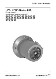
Performance range<br />
H<br />
[ft]<br />
H<br />
[m]<br />
50 Hz<br />
400<br />
1000<br />
200<br />
500<br />
100<br />
100<br />
40<br />
<strong>BM</strong> 3A<br />
<strong>BM</strong> 5A<br />
<strong>BM</strong> 8A<br />
<strong>BM</strong> 17<br />
<strong>BM</strong> 30<br />
<strong>BM</strong> 46<br />
<strong>BM</strong> 60<br />
<strong>BM</strong> 77<br />
<strong>BM</strong> 95<br />
<strong>BM</strong> 125<br />
50<br />
20<br />
<strong>BM</strong> 4"<br />
<strong>BM</strong> 6"<br />
<strong>BM</strong> 8"<br />
10<br />
0.8 1 1 2 4 6 8 10 20 40 60 80 100 200<br />
Q [m³/h]<br />
5 7.5 10 25 50 75 100 250 500 750<br />
Q [US GPM]<br />
TM01 1230 2398<br />
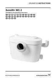
Performance range<br />
H<br />
[ft]<br />
1000<br />
H<br />
[m]<br />
400<br />
60 Hz<br />
500<br />
200<br />
100<br />
80<br />
60<br />
40<br />
<strong>BM</strong> 3A<br />
<strong>BM</strong> 5A<br />
<strong>BM</strong> 8A<br />
<strong>BM</strong> 17<br />
<strong>BM</strong> 30<br />
<strong>BM</strong> 46<br />
<strong>BM</strong> 60<br />
<strong>BM</strong> 77<br />
<strong>BM</strong> 95<br />
<strong>BM</strong> 125<br />
100<br />
50<br />
20<br />
<strong>BM</strong> 4"<br />
<strong>BM</strong> 6"<br />
<strong>BM</strong> 8"<br />
10<br />
1 2 4 6 8 10 20 40 60 80 100 200<br />
Q [m³/h]<br />
5 7.5 10 25 50 75 100 250 500 750<br />
Q [US GPM]<br />
TM01 1232 2398<br />
3
General data<br />
<strong>BM</strong> 4", 6" <strong>and</strong> 8"<br />
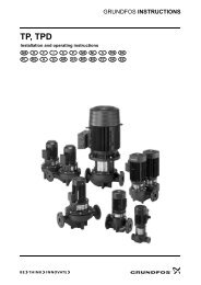
Applications<br />
The Grundfos <strong>BM</strong> booster module is suitable for industrial<br />
<strong>and</strong> water supply applications requiring increased<br />
system pressure.<br />
The booster module is the optimum solution for applications<br />
requiring<br />
• sealless pumps,<br />
• pumps capable of coping with high system pressures,<br />
• high heads,<br />
• quiet operation,<br />
• a minimum of maintenance.<br />
Typical applications<br />
<strong>BM</strong> booster modules are suitable for the following typical<br />
applications:<br />
• Water treatment such as:<br />
– reverse osmosis in domestic water supply<br />
systems,<br />
– hospitals, laboratories, chemical, electronics <strong>and</strong><br />
metal industries,<br />
– ultra-filtration in chemical <strong>and</strong> galvanic industries,<br />
– painting workshops, metal <strong>and</strong> mineral industries.<br />
• Liquid transfer.<br />
• Pressure boosting.<br />
• Closed circulation systems with a high static pressure.<br />
St<strong>and</strong>ard pumps<br />
The following st<strong>and</strong>ard pumps are available for the <strong>BM</strong><br />
booster modules:<br />
• SP 3A, SP 5A <strong>and</strong> SP 8A in 4" sleeve.<br />
• SP 17, SP 30, SP 46 <strong>and</strong> SP 60 in 6" sleeve.<br />
• SP 30, SP 46, SP 60, SP 77, SP 95 <strong>and</strong><br />
SP 125 in 8" sleeve.<br />
Note: The <strong>BM</strong> booster modules are supplied without<br />
non-return valves.<br />
Pumped liquids<br />
Thin, non-explosive liquids not containing abrasive particles<br />
or fibres. The liquid must not attack the pump<br />
materials chemically or mechanically.<br />
If the density <strong>and</strong>/or viscosity of the pumped liquid is<br />
higher than that of water, it may be necessary to use<br />
motors with a higher output than the st<strong>and</strong>ard output<br />
stated.<br />
Construction<br />
Modified st<strong>and</strong>ard submersible pumps are used for the<br />
<strong>BM</strong> booster modules. Pump <strong>and</strong> motor are centred in<br />
the stainless steel sleeve.<br />
Both sleeve ends can be connected to the piping by<br />
means of Victaulic couplings.<br />
A terminal box for electrical connection is placed at the<br />
discharge end.<br />
The sleeve of 4", 6" <strong>and</strong> 8" modules is supplied with<br />
straight pipe inlet <strong>and</strong> outlet.<br />
<strong>BM</strong> 4" is also available with 90° bends at the suction<br />
<strong>and</strong> discharge ends.<br />
Motor<br />
Asynchronous submersible squirrel-cage motor of the<br />
canned type with water-lubricated bearings.<br />
Voltages: 3 x 380-415 V –10%/+6.<br />
3 x 440-480 V –10%/+6.<br />
Enclosure class: IP 54/IP 58.<br />
Insulation class: B (for MS 4000).<br />
F (for MS 6000 <strong>and</strong> Franklin 8").<br />
Special versions: Other voltages are available on<br />
request.<br />
Operating conditions<br />
Flow:<br />
Head:<br />
50 Hz: Max. 160 m³/h, 704 USGPM.<br />
60 Hz: Max. 180 m³/h, 793 USGPM.<br />
Max. 470 m/1542 ft.<br />
Higher performance is possible by<br />
connection in series or in parallel.<br />
Temperature: Max. 40°C/104°F.<br />
(Contact Grundfos in case of higher temperature.)<br />
Outlet pressure:<br />
Max. 80 bar/1160 p.s.i.<br />
Recommended inlet pressure at 25°C/77°F<br />
<strong>BM</strong><br />
Min.<br />
Max.<br />
type [bar] [p.s.i.] [bar] [p.s.i.]<br />
4" 0.5 7.25 60 870<br />
6" 0.5 7.25 50 725<br />
8" 1 14.5 25 363<br />
Rated speed: 50 Hz: 2870 min -1 .<br />
60 Hz: 3450 min -1 .<br />
Sound pressure level:<br />
The sound pressure level of <strong>BM</strong> 4"<br />
<strong>and</strong> <strong>BM</strong> 6" booster modules is below<br />
70 dB(A).<br />
The sound pressure level of <strong>BM</strong> 8"<br />
is below 80 dB(A).<br />
See also "Limitations to operation" on page 8.<br />
4
General data<br />
<strong>BM</strong> 4", 6" <strong>and</strong> 8"<br />
<strong>BM</strong> types <strong>and</strong> versions<br />
<strong>BM</strong> 4" straight version <strong>BM</strong> 6"<br />
TM00 3793 3598<br />
TM00 4019 0998<br />
<strong>BM</strong> 4" elbow version <strong>BM</strong> 8"<br />
TM00 3794 3598<br />
TM01 1420 0998<br />
Sectional drawings<br />
<strong>BM</strong> 4"<br />
7 8 5 4 3<br />
2 9<br />
1<br />
TM00 3795 3598<br />
<strong>BM</strong> 6"<br />
<strong>BM</strong> 8"<br />
2 7 8 5 4 3<br />
6 9<br />
1<br />
TM00 3796 3598<br />
1. Sleeve<br />
2. Discharge connection<br />
3. Suction connection<br />
4. Submersible motor<br />
5. Submersible pump<br />
6. Cable inlet<br />
7. Terminal box<br />
8. Inlet bypass valve<br />
9. Locking system for <strong>BM</strong> 8". <strong>BM</strong> 4" <strong>and</strong><br />
<strong>BM</strong> 6" have a left-h<strong>and</strong> thread for locking.<br />
2 7 8 5 9<br />
4 3<br />
1<br />
TM01 1419 3598<br />
5
Technical data<br />
<strong>BM</strong> 4", 6" <strong>and</strong> 8"<br />
Materials Example: <strong>BM</strong> 46<br />
Pos. Components Materials<br />
N version R version<br />
W.-Nr. AISI W.-Nr. AISI<br />
3 Valve seat<br />
Stainless steel/<br />
NBR<br />
1.4401 316 1.4539 904L<br />
4 Top chamber Stainless steel 1.4401 316 1.4539 904L<br />
6<br />
6b<br />
Top bearing<br />
Bottom bearing<br />
Stainless steel/<br />
NBR<br />
1.4401 316 1.4539 904L<br />
7 Neck ring NBR/PPS – – – –<br />
8<br />
8a<br />
Intermediate<br />
bearing<br />
Spacing washer<br />
for stop ring<br />
NBR – – – –<br />
Carbon/graphite,<br />
PTFE<br />
– – – 904L<br />
8b Stop ring Stainless steel 1.4401 316 1.4539 904L<br />
9 Chamber Stainless steel 1.4401 316 1.4539 904L<br />
10<br />
Bottom<br />
chamber with<br />
stop ring<br />
Stainless steel 1.4401 316 1.4539 904L<br />
11<br />
Nut for split<br />
cone<br />
Stainless steel 1.4401 316 1.4539 904L<br />
11c Nut for stop ring Stainless steel 1.4401 316 1.4539 904L<br />
12 Split cone Stainless steel 1.4401 316 1.4539 904L<br />
13 Impeller Stainless steel 1.4401 316 1.4539 904L<br />
14<br />
Suction interconnector<br />
Stainless steel 1.4401 316 1.4539 904L<br />
15 Strainer Stainless steel 1.4401 316 1.4539 904L<br />
16 Shaft Stainless steel 1.4460 329 1.4462<br />
SAF<br />
2205<br />
17 Strap Stainless steel 1.4401 316 1.4539 904L<br />
19 Nut for strap Stainless steel 1.4401 316 1.4539 904L<br />
24 Coupling Stainless steel 1.4460 329 1.4462<br />
SAF<br />
2205<br />
72 Wear ring Stainless steel 1.4401 316 1.4539 904L<br />
73 Sleeve Stainless steel 1.4401 316 1.4539 904L<br />
MS 4000/MS 6000<br />
1 Shaft Stainless steel 1.4462 SAF 2205 1.4462<br />
SAF<br />
2205<br />
2 Shaft seal<br />
Tungsten<br />
carbide/ceramic<br />
3 Motor sleeve Stainless steel 1.4539 904L 1.4539 904L<br />
Motor end<br />
4<br />
shield<br />
5 Radial bearing<br />
Stainless steel 1.4539 904L 1.4539 904L<br />
Ceramic/<br />
tungsten carbide<br />
6 Thrust bearing Ceramic/carbon<br />
Rubber parts NBR/Buna N<br />
Franklin<br />
1 Shaft<br />
Stainless steel/<br />
carbon<br />
1.4542 630<br />
Ceramic /Buna N<br />
2 Shaft seal<br />
+1.4301<br />
3 Motor sleeve 1.4571 316Ti<br />
4<br />
Motor end<br />
shield<br />
Stainless steel 1.4401 316<br />
5 Radial bearing Steel/carbon<br />
6 Thrust bearing Steel/carbon<br />
Rubber parts NBR/Buna N<br />
17<br />
19<br />
Example: MS 4000<br />
4<br />
6<br />
16<br />
72<br />
7<br />
8<br />
9<br />
11<br />
12<br />
8b<br />
6b<br />
8a<br />
11c<br />
14<br />
24<br />
73<br />
1<br />
2<br />
5<br />
3<br />
13<br />
10<br />
TM01 1520 4997<br />
5<br />
6<br />
4<br />
73<br />
TM01 1522 4997<br />
6
Technical data<br />
<strong>BM</strong> 4", 6" <strong>and</strong> 8"<br />
Type key<br />
Example <strong>BM</strong> 3 (A) 24 N E<br />
Booster module<br />
Pump type /rated flow rate in m³/h<br />
Generation<br />
Number of stages<br />
Materials<br />
<strong>BM</strong> 4" Sleeve Pump Motor<br />
N = 1.4401/316 1.4401/316 1.4539/904<br />
NE = 1.4401/316 1.4401/316 1.4539/904<br />
R = 1.4539/904L 1.4539/904L 1.4539/904L<br />
<strong>BM</strong> 6"<br />
N = 1.4401/316 1.4401/316 1.4539/904<br />
NE = 1.4401/316 1.4401/316 1.4539/904<br />
R = 1.4539/904L 1.4539/904L 1.4539/904L<br />
<strong>BM</strong> 8"<br />
N = 1.4401/316 1.4401/316 1.4401/316<br />
NE = 1.4401/316 1.4401/316 1.4401/316<br />
Special versions, e.g. 1.4301, are available on request.<br />
NE = Pump rubber parts in FKM.<br />
Installation<br />
Modules connected in series <strong>and</strong> in parallel<br />
Connections<br />
Size<br />
<strong>BM</strong> type<br />
Victaulic coupling<br />
Style 77<br />
<strong>BM</strong> 4" <strong>BM</strong> 3A - <strong>BM</strong> 8A 1¼ / ø42 mm<br />
<strong>BM</strong> 6" <strong>BM</strong> 17 - <strong>BM</strong> 60 3" / ø89 mm<br />
<strong>BM</strong> 8" <strong>BM</strong> 30 - <strong>BM</strong> 46 3" / ø89 mm<br />
<strong>BM</strong> 8" <strong>BM</strong> 60 4" / ø114 mm<br />
<strong>BM</strong> 8" <strong>BM</strong> 77 - <strong>BM</strong> 95 5" / ø139 mm<br />
<strong>BM</strong> 8" <strong>BM</strong> 125 6"/ ø168 mm<br />
Legend<br />
Air Air escape escape valve valve<br />
Closing valve<br />
Non-return valve<br />
Pressure switch switch<br />
Flow Flow switch switch<br />
Pressure<br />
Pressure<br />
gauge<br />
gauge<br />
Motor-operated valve<br />
Motor operated valve<br />
Diaphragm<br />
Diaphragm tank<br />
TM00 3764 1094<br />
Bypass<br />
4<br />
Bypass<br />
4<br />
3<br />
2<br />
Bypass<br />
3<br />
1<br />
TM00 3760 1094<br />
2<br />
1<br />
TM00 3762 1094<br />
Booster unit with four modules connected in series,<br />
mounted above each other.<br />
Booster unit with two modules connected in series <strong>and</strong><br />
in parallel, mounted above each other.<br />
Bypass<br />
Bypass<br />
4<br />
Bypass<br />
Bypass<br />
3<br />
4<br />
3<br />
Bypass<br />
2<br />
1<br />
TM00 3761 1094<br />
2<br />
1<br />
TM00 3763 1094<br />
Booster unit with four modules connected in parallel,<br />
mounted above each other.<br />
Booster unit with four modules connected in series with<br />
bypass, mounted above each other.<br />
7
Technical data<br />
<strong>BM</strong> 4", 6" <strong>and</strong> 8"<br />
Limitations to operation<br />
The capacity of the modules should always be kept<br />
within the recommended flow <strong>and</strong> pressure range of<br />
each individual pump.<br />
Recommended flow at 25°C/77°F<br />
Type<br />
m³/h<br />
US GPM<br />
50 Hz 60 Hz 50 Hz 60 Hz<br />
<strong>BM</strong> 3A 0.8-4.4 1.0-4.7 3.5-20 4.4-21<br />
<strong>BM</strong> 5A 2.5-6.8 3.0-7.7 11-30 13-34<br />
<strong>BM</strong> 8A 4.0-10 4.8-10 17-44 21-44<br />
<strong>BM</strong> 17 8.0-24 7.0-29 35-105 31-128<br />
<strong>BM</strong> 30 15-37 19-45 66-162 84-198<br />
<strong>BM</strong> 46 24-60 28-72 106-264 123-317<br />
<strong>BM</strong> 60 35-75 37-90 154-330 163-396<br />
<strong>BM</strong> 77 38-96 48-120 167-423 211-528<br />
<strong>BM</strong> 95 47-118 57-143 206-519 251-629<br />
<strong>BM</strong> 125 62-156 75-187 273-686 330-823<br />
Recommended pressure<br />
Inlet pressure<br />
Outlet pressure<br />
<strong>BM</strong><br />
Type<br />
Min. Max. Max.<br />
[bar] [p.s.i.] [bar] [p.s.i.] [bar] [p.s.i.]<br />
4" 0.5 7.25 60 870 80 1160<br />
6" 0.5 7.25 50 725 80 1160<br />
8" 1 14.5 25 362 70 1015<br />
Note: If the max. inlet/outlet pressure is exceeded, a<br />
safety valve should be installed.<br />
Maximum permissible liquid temperature<br />
Maximum liquid<br />
temperature<br />
Minimum flow<br />
velocity past the<br />
motor<br />
Automatic control devices<br />
Minimum<br />
flow<br />
Motor<br />
°C m/s m³/h<br />
Grundfos 4" 40 0.15 0.8<br />
Grundfos 6" 40 0.15 5.5<br />
Franklin 8" 30 0.16 18.5<br />
To protect the pumps against dry running <strong>and</strong> to ensure<br />
a minimum flow of cooling water past the motors, the<br />
system must be fitted with flow <strong>and</strong> pressure control<br />
devices.<br />
A pressure switch on the suction side is sized in accordance<br />
with the estimated inlet pressure. At a pressure<br />
lower than 0.5 bar/7.25 p.s.i. for <strong>BM</strong> 4" <strong>and</strong> <strong>BM</strong> 6", <strong>and</strong><br />
1 bar/14.5 p.s.i. for <strong>BM</strong> 8", an alarm is given <strong>and</strong> shortly<br />
after the pumps will stop (max. 15 sec).<br />
All discharge connections to the system should be fitted<br />
with flow switches which will stop the system at the set<br />
minimum flows.<br />
The above control devices ensure a correct inlet pressure<br />
<strong>and</strong> a minimum flow of cooling water past the<br />
motor.<br />
Flow switch cuttingin is adjusted for a minimum time<br />
delay equivalent to the maximum starting frequency of<br />
the system.<br />
Checking of operation<br />
Depending on the number of operating hours of the<br />
pumps, the following should be checked at suitable<br />
intervals:<br />
1. Flow.<br />
2. Starting frequency.<br />
3. Control <strong>and</strong> protective devices.<br />
4. Liquid temperature.<br />
5. Minimum flow through modules during operation.<br />
Performance data<br />
Curve conditions<br />
The guidelines below apply to the curves on the following<br />
pages.<br />
1. The curves apply to actual speeds at 50 Hz or<br />
60 Hz.<br />
The bold curves indicate the permissible duty<br />
range.<br />
The thin curves are only intended as a guide.<br />
All curves are based on average values according<br />
to ISO 9906 Annex A.<br />
If a minimum performance is required, individual<br />
measurements must be carried out.<br />
The curves apply to a kinematic viscosity of 1 mm²/s<br />
(1 cSt).<br />
The power curve P2/hp shows pump power input<br />
per stage.<br />
The efficiency curve η shows pump efficiency, i.e.<br />
pump without motor.<br />
The performance tests have been made at a water<br />
temperature of 20°C.<br />
Test liquid: Airless water.<br />
2. The conversion between head H (m) <strong>and</strong> pressure<br />
p (kPa) has been made for water with a density of<br />
ρ = 1000 kg/m³. If the density differs from this value,<br />
the created pressure will be proportional to the density.<br />
Series operation (high pressure)<br />
If a pressure higher than that of a single module is<br />
required, several modules are connected in series. The<br />
resulting pressure is found by adding the pressure of<br />
each individual module. The flow will be the same as for<br />
one pump.<br />
Note: Make sure that the maximum inlet pressure is not<br />
exceeded, see "Operating conditions" page 4.<br />
Parallel operation (high flow)<br />
If a flow higher than that of a single module is required,<br />
several modules are connected in parallel. The resulting<br />
flow is found by adding the flow of each individual<br />
module. The pressure will be the same as for one<br />
pump.<br />
8
Performance curves, 50 Hz<br />
<strong>BM</strong> 3A<br />
<strong>BM</strong> 3A<br />
H<br />
[ft]<br />
1200<br />
H<br />
[m]<br />
380<br />
360<br />
-60<br />
<strong>BM</strong> 3A<br />
50 Hz<br />
ISO 9906 Annex A<br />
340<br />
320<br />
-52<br />
1000<br />
300<br />
280<br />
-45<br />
260<br />
800<br />
240<br />
220<br />
-33<br />
200<br />
600<br />
180<br />
160<br />
-25<br />
140<br />
400<br />
120<br />
-18<br />
100<br />
80<br />
-12<br />
200<br />
60<br />
-9<br />
40<br />
-6<br />
20<br />
0<br />
0<br />
0.0 0.4 0.8 1.2 1.6 2.0 2.4 2.8 3.2 3.6 4.0 Q [m³/h]<br />
P2<br />
hp<br />
0.15<br />
0 4 8 12 16 Q [US GPM]<br />
P2<br />
[kW]<br />
Eta<br />
0.10<br />
Eta<br />
[%]<br />
50<br />
0.10<br />
0.08<br />
0.06<br />
P2<br />
40<br />
30<br />
0.05<br />
0.04<br />
20<br />
0.00<br />
0.02<br />
0.00<br />
0.0 0.4 0.8 1.2 1.6 2.0 2.4 2.8 3.2 3.6 4.0 Q [m³/h]<br />
10<br />
0<br />
TM01 1212 3400<br />
9
Performance curves, 50 Hz<br />
<strong>BM</strong> 5A<br />
<strong>BM</strong> 5A<br />
H<br />
[ft]<br />
1200<br />
H<br />
[m]<br />
380<br />
360<br />
-60<br />
<strong>BM</strong> 5A<br />
50 Hz<br />
ISO 9906 Annex A<br />
340<br />
320<br />
1000<br />
300<br />
280<br />
-44<br />
800<br />
260<br />
240<br />
-38<br />
220<br />
-33<br />
200<br />
600<br />
180<br />
160<br />
-25<br />
140<br />
400<br />
120<br />
-17<br />
100<br />
80<br />
-12<br />
200<br />
60<br />
40<br />
20<br />
0<br />
0<br />
0.0 0.8 1.6 2.4 3.2 4.0 4.8 5.6 6.4 Q [m³/h]<br />
P2<br />
hp<br />
0.15<br />
0 5 10 15 20 25 Q [US GPM]<br />
P2<br />
[kW]<br />
Eta<br />
0.10<br />
Eta<br />
[%]<br />
50<br />
0.10<br />
0.08<br />
0.06<br />
P2<br />
40<br />
30<br />
0.05<br />
0.04<br />
20<br />
0.00<br />
0.02<br />
0.00<br />
0.0 0.8 1.6 2.4 3.2 4.0 4.8 5.6 6.4 Q [m³/h]<br />
10<br />
0<br />
TM01 1213 3400<br />
10
Performance curves, 50 Hz<br />
<strong>BM</strong> 8A<br />
<strong>BM</strong> 8A<br />
H<br />
[ft]<br />
700<br />
H<br />
[m]<br />
220<br />
-37<br />
<strong>BM</strong> 8A<br />
50 Hz<br />
ISO 9906 Annex A<br />
200<br />
600<br />
180<br />
160<br />
500<br />
-25<br />
140<br />
-21<br />
400<br />
120<br />
-18<br />
100<br />
300<br />
-15<br />
80<br />
-12<br />
200<br />
60<br />
-10<br />
40<br />
-7<br />
100<br />
-5<br />
20<br />
0<br />
0<br />
0 1 2 3 4 5 6 7 8 9 10 Q [m³/h]<br />
P2<br />
hp<br />
0.3<br />
0 10 20 30 40 Q [US GPM]<br />
P2<br />
[kW]<br />
Eta<br />
0.20<br />
Eta<br />
[%]<br />
50<br />
0.2<br />
0.16<br />
0.12<br />
P2<br />
40<br />
30<br />
0.1<br />
0.08<br />
20<br />
0.0<br />
0.04<br />
0.00<br />
0 1 2 3 4 5 6 7 8 9 10 Q [m³/h]<br />
10<br />
0<br />
TM01 1214 3400<br />
11
Performance curves, 50 Hz<br />
<strong>BM</strong> 17<br />
<strong>BM</strong> 17<br />
H<br />
[ft]<br />
1600<br />
H<br />
[m]<br />
480<br />
<strong>BM</strong> 17<br />
50 Hz<br />
ISO 9906 Annex A<br />
1400<br />
440<br />
-40<br />
-38<br />
400<br />
1200<br />
360<br />
-32<br />
320<br />
1000<br />
-26<br />
280<br />
800<br />
240<br />
-22<br />
-19<br />
200<br />
600<br />
-16<br />
160<br />
-13<br />
400<br />
120<br />
-9<br />
80<br />
200<br />
-5<br />
40<br />
0<br />
0<br />
0 2 4 6 8 10 12 14 16 18 20 Q [m³/h]<br />
P2<br />
hp<br />
0.9<br />
0.6<br />
0 20 40 60 80 Q [US GPM]<br />
P2<br />
[kW]<br />
0.8<br />
0.6<br />
0.4<br />
Eta<br />
P2<br />
Eta<br />
[%]<br />
80<br />
60<br />
40<br />
0.3<br />
0.0<br />
0.2<br />
0.0<br />
0 2 4 6 8 10 12 14 16 18 20 Q [m³/h]<br />
20<br />
0<br />
TM00 3699 3400<br />
12
Performance curves, 50 Hz<br />
<strong>BM</strong> 30<br />
<strong>BM</strong> 30<br />
H<br />
[ft]<br />
H<br />
[m]<br />
400<br />
-35<br />
<strong>BM</strong> 30<br />
50 Hz<br />
ISO 9906 Annex A<br />
1200<br />
360<br />
-31<br />
320<br />
1000<br />
-26<br />
280<br />
800<br />
240<br />
-21<br />
200<br />
-17<br />
600<br />
-15<br />
160<br />
-13<br />
400<br />
120<br />
-11<br />
-8<br />
80<br />
-6<br />
200<br />
40<br />
-4<br />
-3<br />
0<br />
0<br />
0 4 8 12 16 20 24 28 32 36 Q [m³/h]<br />
P2<br />
hp<br />
1.8<br />
0 40 80 120 160 Q [US GPM]<br />
P2<br />
[kW]<br />
1.6<br />
Eta<br />
1.2<br />
Eta<br />
[%]<br />
80<br />
60<br />
1.2<br />
0.8<br />
P2<br />
40<br />
0.6<br />
0.0<br />
0.4<br />
0.0<br />
0 4 8 12 16 20 24 28 32 36 Q [m³/h]<br />
20<br />
0<br />
TM01 2074 3400<br />
13
Performance curves, 50 Hz<br />
<strong>BM</strong> 46<br />
<strong>BM</strong> 46<br />
H<br />
[ft]<br />
1200<br />
H<br />
[m]<br />
360<br />
<strong>BM</strong> 46<br />
50 Hz<br />
ISO 9906 Annex A<br />
320<br />
-24<br />
1000<br />
280<br />
-20<br />
800<br />
240<br />
-19<br />
-17<br />
600<br />
200<br />
160<br />
-15<br />
-12<br />
400<br />
200<br />
120<br />
80<br />
40<br />
-10<br />
-8<br />
-7<br />
-6<br />
-5<br />
-3<br />
-2<br />
0<br />
0<br />
0 8 16 24 32 40 48 56 64 Q [m³/h]<br />
P2<br />
hp<br />
1.8<br />
1.2<br />
0 50 100 150 200 250 Q [US GPM]<br />
P2<br />
[kW]<br />
1.6<br />
P2<br />
1.2<br />
Eta<br />
0.8<br />
Eta<br />
[%]<br />
80<br />
60<br />
40<br />
0.6<br />
0.0<br />
0.4<br />
0.0<br />
0 8 16 24 32 40 48 56 64 Q [m³/h]<br />
20<br />
0<br />
TM01 1217 3400<br />
14
Performance curves, 50 Hz<br />
<strong>BM</strong> 60<br />
<strong>BM</strong> 60<br />
H<br />
[ft]<br />
1000<br />
H<br />
[m]<br />
320<br />
300<br />
-22<br />
<strong>BM</strong> 60<br />
50 Hz<br />
ISO 9906 Annex A<br />
280<br />
-20<br />
260<br />
800<br />
240<br />
220<br />
-16<br />
-15<br />
200<br />
600<br />
180<br />
-12<br />
160<br />
140<br />
-10<br />
400<br />
120<br />
-8<br />
100<br />
-7<br />
80<br />
-6<br />
-5<br />
200<br />
60<br />
40<br />
20<br />
0<br />
0<br />
0 8 16 24 32 40 48 56 64 72 Q [m³/h]<br />
P2<br />
hp<br />
4<br />
3<br />
2<br />
0 50 100 150 200 250 300 Q [US GPM]<br />
P2<br />
[kW]<br />
3.2<br />
2.4<br />
Eta<br />
1.6<br />
P2<br />
Eta<br />
[%]<br />
80<br />
60<br />
40<br />
1<br />
0<br />
0.8<br />
0.0<br />
0 8 16 24 32 40 48 56 64 72 Q [m³/h]<br />
20<br />
0<br />
TM01 1218 3400<br />
15
Performance curves, 50 Hz<br />
<strong>BM</strong> 77<br />
<strong>BM</strong> 77<br />
H<br />
[ft]<br />
1400<br />
H<br />
[m]<br />
440<br />
<strong>BM</strong> 77<br />
50 Hz<br />
ISO 9906 Annex A<br />
400<br />
-20<br />
1200<br />
360<br />
320<br />
1000<br />
280<br />
-14<br />
800<br />
240<br />
-12<br />
200<br />
-10<br />
600<br />
160<br />
-8<br />
-7<br />
400<br />
120<br />
-6<br />
80<br />
200<br />
40<br />
0<br />
0<br />
0 10 20 30 40 50 60 70 80 90 Q [m³/h]<br />
P2<br />
hp<br />
0 100 200 300 400 Q [US GPM]<br />
P2<br />
[kW]<br />
Eta<br />
4<br />
Eta<br />
[%]<br />
80<br />
4<br />
3<br />
P2<br />
60<br />
2<br />
0<br />
2<br />
1<br />
0<br />
0 10 20 30 40 50 60 70 80 90 Q [m³/h]<br />
40<br />
20<br />
0<br />
TM01 1219 3400<br />
16
Performance curves, 50 Hz<br />
<strong>BM</strong> 95<br />
<strong>BM</strong> 95<br />
H<br />
[ft]<br />
1400<br />
H<br />
[m]<br />
440<br />
-20<br />
<strong>BM</strong> 95<br />
50 Hz<br />
ISO 9906 Annex A<br />
400<br />
1200<br />
360<br />
-16<br />
320<br />
1000<br />
280<br />
-12<br />
800<br />
240<br />
-10<br />
200<br />
600<br />
-8<br />
160<br />
400<br />
120<br />
-6<br />
80<br />
200<br />
40<br />
0<br />
0<br />
0 10 20 30 40 50 60 70 80 90 100 110 Q [m³/h]<br />
P2<br />
hp<br />
9<br />
6<br />
0 100 200 300 400 Q [US GPM]<br />
P2<br />
[kW]<br />
8<br />
6<br />
Eta<br />
4<br />
P2<br />
Eta<br />
[%]<br />
80<br />
60<br />
40<br />
3<br />
0<br />
2<br />
0<br />
0 10 20 30 40 50 60 70 80 90 100 110 Q [m³/h]<br />
20<br />
0<br />
TM01 2075 3400<br />
17
Performance curves, 50 Hz<br />
<strong>BM</strong> 125<br />
<strong>BM</strong> 125<br />
H<br />
[ft]<br />
H<br />
[m]<br />
280<br />
-9<br />
<strong>BM</strong> 125<br />
50 Hz<br />
ISO 9906 Annex A<br />
260<br />
800<br />
240<br />
220<br />
-7<br />
200<br />
600<br />
180<br />
160<br />
-5<br />
140<br />
400<br />
120<br />
-4<br />
-4-1<br />
100<br />
-3<br />
80<br />
200<br />
60<br />
40<br />
20<br />
0<br />
0<br />
0 20 40 60 80 100 120 140 160Q [m³/h]<br />
P2<br />
hp<br />
15<br />
10<br />
0 200 400 600 Q [US GPM]<br />
P2<br />
[kW]<br />
12<br />
Eta<br />
9<br />
P2<br />
6<br />
Eta<br />
[%]<br />
80<br />
60<br />
40<br />
5<br />
0<br />
3<br />
0<br />
0 20 40 60 80 100 120 140 160Q [m³/h]<br />
20<br />
0<br />
TM01 2076 3400<br />
18
Order data, 50 Hz<br />
<strong>BM</strong> 4"<br />
3 x 380-415 V<br />
Booster module 4", (with straight pipe connections)<br />
Type<br />
Motor output Rated Length<br />
[P 2 ]<br />
current<br />
[L]<br />
Product no. Product no. Product no. Weight [kg]<br />
Ship.<br />
vol.<br />
I N [A]<br />
N version NE version R version<br />
[kW] [hp] [mm] [in] Net Gross [m 3 ]<br />
<strong>BM</strong> 3A-6 0.75 1.0 1.92-1.84 1222 45.0 10731906 10741906 - 31.0 37.0 0.095<br />
<strong>BM</strong> 3A-9 0.75 1.0 1.92-1.84 1222 45.0 10731909 10741909 - 32.0 38.0 0.095<br />
<strong>BM</strong> 3A-12 0.75 1.0 1.92-1.84 1222 45.0 10731912 10741912 - 33.0 39.0 0.095<br />
<strong>BM</strong> 3A-18 1.1 1.5 2.80-2.75 1369 50.8 10731918 10741918 - 37.0 43.0 0.100<br />
<strong>BM</strong> 3A-25 1.5 2.0 3.95-4.10 1640 61.5 10731925 10741925 - 41.0 47.0 0.120<br />
<strong>BM</strong> 3A-33 2.2 3.0 5.85-6.45 1758 66.1 10731933 10741933 - 46.0 52.0 0.126<br />
<strong>BM</strong> 3A-45 3.0 4.0 8.35-8.10 1986 75.1 10731945 10741945 - 53.0 59.0 0.142<br />
<strong>BM</strong> 3A-52 4.0 5.5 9.75-9.80 2346 89.3 10731952 10741952 - 62.0 69.0 0.170<br />
<strong>BM</strong> 3A-60 4.0 5.5 9.75-9.80 2490 95.0 10731960 10741960 - 65.0 72.0 0.175<br />
<strong>BM</strong> 5A-12 1.1 1.5 2.80-2.75 1222 45.0 05731912 05741912 05771912 34.0 40.0 0.095<br />
<strong>BM</strong> 5A-17 1.5 2.0 3.95-4.10 1369 50.8 05731917 05741917 05771917 36.0 42.0 0.100<br />
<strong>BM</strong> 5A-25 2.2 3.0 5.85-6.45 1640 61.5 05731925 05741925 05771925 43.0 49.0 0.120<br />
<strong>BM</strong> 5A-33 3.0 4.0 8.35-8.10 1986 75.1 05731933 05741933 05771933 49.0 55.0 0.142<br />
<strong>BM</strong> 5A-38 4.0 5.5 9.75-9.80 1986 75.1 05731938 05741938 05771938 54.0 60.0 0.142<br />
<strong>BM</strong> 5A-44 4.0 5.5 9.75-9.80 2112 80.1 05731944 05741944 05771944 57.0 64.0 0.149<br />
<strong>BM</strong> 5A-60 5.5 7.5 13.0-13.4 2490 98.0 05731960 05741960 05771960 70.0 77.0 0.175<br />
<strong>BM</strong> 8A-5 0.75 1.0 1.92-1.84 1222 45.0 11731905 11741905 11771905 32.0 38.0 0.095<br />
<strong>BM</strong> 8A-7 1.1 1.5 2.80-2.75 1369 50.8 11731907 11741907 11771907 35.0 41.0 0.100<br />
<strong>BM</strong> 8A-10 1.5 2.0 3.95-4.10 1472 54.9 11731910 11741910 11771910 37.0 43.0 0.106<br />
<strong>BM</strong> 8A-12 2.2 3.0 5.85-6.45 1640 61.5 11731912 11741912 11771912 41.0 47.0 0.120<br />
<strong>BM</strong> 8A-15 2.2 3.0 5.85-6.45 1758 66.1 11731915 11741915 11771915 44.0 50.0 0.126<br />
<strong>BM</strong> 8A-18 3.0 4.0 8.35-8.10 1986 75.1 11731918 11741918 11771918 48.0 54.0 0.142<br />
<strong>BM</strong> 8A-21 4.0 5.5 9.75-9.80 2112 80.1 11731921 11741921 11771921 54.0 61.0 0.149<br />
<strong>BM</strong> 8A-25 4.0 5.5 9.75-9.80 2346 89.3 11731925 11741925 11771925 57.0 64.0 0.170<br />
<strong>BM</strong> 8A-37 5.5 7.5 13.0-13.4 2737 107.8 11731937 11741937 11771937 73.0 81.0 0.192<br />
On request, the <strong>BM</strong> is available:<br />
- in other voltages,<br />
- with all stages indicated in the st<strong>and</strong>ard SP product range.<br />
Dimensional sketch<br />
ø42 / 1 1/4"<br />
+-<br />
L 2 mm / 0.08 in<br />
ø114.3 / 4.5"<br />
102 mm / 4 in<br />
TM00 3797 0299<br />
One set of connecting fittings is required for each system (see "Accessories").<br />
19
Order data, 50 Hz<br />
<strong>BM</strong> 4"<br />
3 x 380-415 V<br />
Booster module 4", (with elbow)<br />
Type<br />
Motor output Rated<br />
Length<br />
[P 2 ]<br />
current<br />
[L]<br />
Product no. Product no. Weight [kg] Ship.<br />
I N [A]<br />
N version NE version<br />
vol. [m 3 ]<br />
[kW] [hp] [mm] [in] Net Gross<br />
<strong>BM</strong> 3A-6 0.75 1.0 1.92-1.84 1144 45.0 10751906 10761906 31.0 37.0 0.095<br />
<strong>BM</strong> 3A-9 0.75 1.0 1.92-1.84 1144 45.0 10751909 10761909 32.0 38.0 0.095<br />
<strong>BM</strong> 3A-12 0.75 1.0 1.92-1.84 1144 45.0 10751912 10761912 33.0 39.0 0.095<br />
<strong>BM</strong> 3A-18 1.1 1.5 2.80-2.75 1291 50.8 10751918 10761918 37.0 43.0 0.100<br />
<strong>BM</strong> 3A-25 1.5 2.0 3.95-4.10 1562 61.5 10751925 10761925 41.0 47.0 0.120<br />
<strong>BM</strong> 3A-33 2.2 3.0 5.85-6.45 1680 66.1 10751933 10761933 46.0 52.0 0.126<br />
<strong>BM</strong> 3A-45 3.0 4.0 8.35-8.10 1908 75.1 10751945 10761945 53.0 59.0 0.142<br />
<strong>BM</strong> 3A-52 4.0 5.5 9.75-9.80 2268 89.3 10751952 10761952 62.0 69.0 0.170<br />
<strong>BM</strong> 3A-60 4.0 5.5 9.75-9.80 2412 95.0 10751960 10761960 65.0 72.0 0.175<br />
<strong>BM</strong> 5A-12 1.1 1.5 2.80-2.75 1144 45.0 05751912 05761912 34.0 40.0 0.095<br />
<strong>BM</strong> 5A-17 1.5 2.0 3.95-4.10 1291 50.8 05751917 05761917 36.0 42.0 0.100<br />
<strong>BM</strong> 5A-25 2.2 3.0 5.85-6.45 1562 61.5 05751925 05761925 43.0 49.0 0.120<br />
<strong>BM</strong> 5A-33 3.0 4.0 8.35-8.10 1908 75.1 05751933 05761933 49.0 55.0 0.142<br />
<strong>BM</strong> 5A-38 4.0 5.5 9.75-9.80 1908 75.1 05751938 05761938 54.0 60.0 0.142<br />
<strong>BM</strong> 5A-44 4.0 5.5 9.75-9.80 2034 80.1 05751944 05761944 57.0 64.0 0.149<br />
<strong>BM</strong> 5A-60 5.5 7.5 13.0-13.4 2412 95.0 05751960 05761960 70.0 77.0 0.175<br />
<strong>BM</strong> 8A-5 0.75 1.0 1.92-1.84 1144 45.0 11751905 11761905 32.0 38.0 0.095<br />
<strong>BM</strong> 8A-7 1.1 1.5 2.80-2.75 1291 50.8 11751907 11761907 35.0 41.0 0.100<br />
<strong>BM</strong> 8A-10 1.5 2.0 3.95-4.10 1394 54.9 11751910 11761910 37.0 43.0 0.106<br />
<strong>BM</strong> 8A-12 2.2 3.0 5.85-6.45 1562 61.5 11751912 11761912 41.0 47.0 0.120<br />
<strong>BM</strong> 8A-15 2.2 3.0 5.85-6.45 1680 66.1 11751915 11761915 44.0 50.0 0.126<br />
<strong>BM</strong> 8A-18 30 4.0 8.35-8.10 1908 75.1 11751918 11761918 48.0 54.0 0.142<br />
<strong>BM</strong> 8A-21 4.0 5.5 9.75-9.80 2034 80.1 11751921 11761921 54.0 61.0 0.149<br />
<strong>BM</strong> 8A-25 4.0 5.5 9.75-9.80 2268 89.3 11751925 11761925 57.0 64.0 0.170<br />
<strong>BM</strong> 8A-37 5.5 7.5 13.0-13.4 2707 106.6 11751937 11761937 73.0 81.0 0.192<br />
On request, the <strong>BM</strong> is available:<br />
- in other voltages,<br />
- with all stages indicated in the st<strong>and</strong>ard SP product range<br />
- in R version.<br />
Dimensional sketch<br />
L + -<br />
2 mm / 0.08 in<br />
102 mm / 4 in<br />
82.5 mm / 3.2 in<br />
ø42 / 1 1/4"<br />
ø114.3 / 4.5"<br />
TM00 3798 0299<br />
One set of connecting fittings is required for each system (please see "Accessories").<br />
20
I<br />
Order data, 50 Hz<br />
<strong>BM</strong> 6"<br />
3 x 380-415 V<br />
Booster module 6", (with straight pipe connections)<br />
Type<br />
Motor output Rated Length<br />
[P 2 ]<br />
current<br />
[L]<br />
Product no. Product no. Product no. Weight [kg]<br />
Ship.<br />
vol.<br />
I N [A]<br />
N version NE version R version<br />
[kW] [hp] [mm] [in] Net Gross [m 3 ]<br />
<strong>BM</strong> 17-5 3.0 4.0 8.10-8.35 1550 61.0 12CE1905 12CF1905 12CU1905 49 71 0.273<br />
<strong>BM</strong> 17-7 4.0 5.5 9.75-9.80 1750 68.9 12CE1907 12CF1907 12CU1907 59 85 0.304<br />
<strong>BM</strong> 17-9 5.5 7.5 13.0-13.4 1950 76.8 12CE1909 12CF1909 12CU1909 69 99 0.335<br />
<strong>BM</strong> 17-13 7.5 10.0 17.6-17.8 2200 86.6 12CE1913 12CF1913 12CU1913 90 128 0.340<br />
<strong>BM</strong> 17-16 9.2 12.5 21.8-21.8 2500 98.4 12CE1916 12CF1916 12CU1916 104 148 0.421<br />
<strong>BM</strong> 17-19 11.0 15.0 25.5-25-8 2700 106.3 12CE1919 12CF1919 12CU1919 114 162 0.452<br />
<strong>BM</strong> 17-22 13.0 17.5 30.5-31.0 2850 112.2 12CE1922 12CF1922 12CU1922 122 173 0.476<br />
<strong>BM</strong> 17-26 15.0 20.0 34.0-34.5 3050 120.1 12CE1926 12CF1926 12CU1926 134 190 0.507<br />
<strong>BM</strong> 17-32 18.5 25.0 42.0-42.5 3800 149.6 12CE1932 12CF1932 12CU1932 158 223 0.624<br />
<strong>BM</strong> 17-38 22.0 30.0 47.5-50.0 4250 167.3 12CE1938 12CF1938 12CU1938 178 251 0.694<br />
<strong>BM</strong> 17-40 22.0 30.0 47.5-50.0 4250 167.3 12CE1940 12CF1940 12CU1940 181 255 0.694<br />
<strong>BM</strong> 30-3 3.0 4.0 8.10-8.35 1550 61.0 13CE1903 13CF1903 13CU1903 48 69 0.273<br />
<strong>BM</strong> 30-4 4.0 5.5 9.75-9.80 1750 68.9 13CE1904 13CF1904 13CU1904 56 80 0.304<br />
<strong>BM</strong> 30-6 5.5 7.5 13.0-13.4 2100 82.7 13CE1906 13CF1906 13CU1906 67 96 0.335<br />
<strong>BM</strong> 30-8 7.5 10.0 17.6-17.8 2100 82.7 13CE1908 13CF1908 13CU1908 87 124 0.356<br />
<strong>BM</strong> 30-11 9.2 12.5 21.8-21.8 2500 98.4 13CE1911 13CF1911 13CU1911 103 146 0.421<br />
<strong>BM</strong> 30-13 11.0 15.0 25.5-25-8 2700 106.3 13CE1913 13CF1913 13CU1913 113 160 0.452<br />
<strong>BM</strong> 30-15 13.0 17.5 30.5-31.0 2850 112.2 13CE1915 13CF1915 13CU1915 121 171 0.476<br />
<strong>BM</strong> 30-17 15.0 20.0 34.0-34.5 3200 126.0 13CE1917 13CF1917 13CU1917 131 185 0.530<br />
<strong>BM</strong> 30-21 18.5 25.0 42.0-42.5 3800 149.6 13CE1921 13CF1921 13CU1921 155 219 0.624<br />
<strong>BM</strong> 30-26 22.0 30.0 47.5-50.0 4250 167.3 13CE1926 13CF1926 13CU1926 176 248 0.694<br />
<strong>BM</strong> 30-31 26.0 35.0 57.0-59.0 4950 194.9 13CE1931 13CF1931 13CU1931 195 275 0.713<br />
<strong>BM</strong> 30-35 30.0 40.0 66.5-68.5 5100 200.8 13CE1935 13CF1935 13CU1935 216 304 0.735<br />
<strong>BM</strong> 46-2 3.0 4.0 8.10-8.35 1550 61.0 15C81902 15C91902 15C71902 46 66 0.273<br />
<strong>BM</strong> 46-3 5.5 7.5 13.0-13.4 1750 68.9 15C81903 15C91903 15C71903 63 90 0.304<br />
<strong>BM</strong> 46-5 7.5 10.0 17.6-17.8 1950 76.8 15C81905 15C91905 15C71905 82 117 0.335<br />
<strong>BM</strong> 46-6 9.2 12.5 21.8-21.8 2100 82.7 15C81906 15C91906 15C71906 94 134 0.356<br />
<strong>BM</strong> 46-7 11.0 15.0 25.5-25.8 2200 86.6 15C81907 15C91907 15C71907 101 143 0.374<br />
<strong>BM</strong> 46-8 13.0 17.5 30.5-31.0 2500 98.4 15C81908 15C91908 15C71908 108 153 0.421<br />
<strong>BM</strong> 46-10 15.0 20.0 34.0-34.5 2700 106.3 15C81910 15C91910 15C71910 123 174 0.452<br />
<strong>BM</strong> 46-12 18.5 25.0 42.0-42.5 3050 120.1 15C81912 15C91912 15C71912 136 192 0.507<br />
<strong>BM</strong> 46-15 22.0 30.0 47.5-50.0 3400 133.9 15C81915 15C91915 15C71915 157 222 0.562<br />
<strong>BM</strong> 46-17 26.0 35.0 57.0-59.0 3800 149.6 15C81917 15C91917 15C71917 174 246 0.624<br />
<strong>BM</strong> 46-19 30.0 40.0 66.5-68.5 4250 167.3 15C81919 15C91919 15C71919 187 264 0.694<br />
<strong>BM</strong> 60-5 9.2 12.5 21.8-21.8 1950 76.8 14CE1905 14CF1905 14C71905 89 127 0.335<br />
<strong>BM</strong> 60-6 11.0 15.0 25.5-25.8 2100 82.7 14CE1906 14CF1906 14C71906 98 139 0.356<br />
<strong>BM</strong> 60-7 13.0 17.5 30.5-31.0 2200 86.6 14CE1907 14CF1907 14C71907 104 148 0.390<br />
<strong>BM</strong> 60-8 15.0 20.0 34.0-34.5 2500 98.4 14CE1908 14CF1908 14C71908 116 164 0.421<br />
<strong>BM</strong> 60-10 18.5 25.0 42.0-42.5 2700 106.3 14CE1910 14CF1910 14C71910 129 183 0.452<br />
<strong>BM</strong> 60-12 22.0 30.0 47.5-50.0 3050 120.1 14CE1912 14CF1912 14C71912 145 205 0.507<br />
<strong>BM</strong> 60-15 26.0 35.0 57.0-59.0 3400 133.9 14CE1915 14CF1915 14C71915 163 230 0.562<br />
<strong>BM</strong> 60-16 30.0 40.0 66.5-68.5 3800 149.6 14CE1916 14CF1916 14C71916 180 254 0.624<br />
On request, the <strong>BM</strong> is available in other voltages <strong>and</strong> with all stages indicated in the st<strong>and</strong>ard SP product range.<br />
Dimensional sketch<br />
L 4 mm / 0.16 in<br />
164mm / 6.5 in<br />
ø88.9 / 3"<br />
ø168.3 / 6 3/5"<br />
MADE<br />
N<br />
DENMARK<br />
TM00 3799 0299<br />
One set of connecting fittings is required for each system (please see "Accessories").<br />
21
Order data, 50 Hz<br />
<strong>BM</strong> 8"<br />
3 x 380-415 V<br />
Booster module 8", (with straight pipe connections)<br />
Type<br />
Motor output Rated<br />
Length<br />
[P 2 ]<br />
current<br />
[L]<br />
Product no. Product no. Weight [kg] Ship.<br />
I N [A]<br />
N version NE version<br />
vol. [m 3 ]<br />
[kW] [hp] [mm] [in] Net Gross<br />
<strong>BM</strong> 46-20 37.0 50.0 74.0-77.0 4150 175.2 15CR1920 15CT1920 329 471 1.65<br />
<strong>BM</strong> 46-24 37.0 50.0 74.0-77.0 4950 194.9 15CR1924 15CT1924 347 509 1.83<br />
<strong>BM</strong> 60-20 37.0 50.0 74.0-77.0 4150 163.4 14CR1920 14CT1920 323 453 1.54<br />
<strong>BM</strong> 60-22 45.0 60.0 90.0-92.0 4450 175.2 14CR1922 14CT1922 332 474 1.65<br />
<strong>BM</strong> 77-6 22.0 30.0 47.5-50.0 2750 108.3 16CE1906 16CF1906 194 268 1.04<br />
<strong>BM</strong> 77-7 26.0 35.0 57.0-59.0 2750 108.3 16CE1907 16CF1907 204 278 1.04<br />
<strong>BM</strong> 77-8 30.0 40.0 66.5-68.5 3200 126.0 16CE1908 16CF1908 225 317 1.20<br />
<strong>BM</strong> 77-10 37.0 50.0 74.0-77.0 3450 135.8 16CR1910 16CT1910 307 409 1.29<br />
<strong>BM</strong> 77-12 45.0 60.0 90.0-92.0 3800 149.6 16CR1912 16CT1912 320 436 1.42<br />
<strong>BM</strong> 77-14 55.0 75.0 109.0-111.0 4150 163.4 16CR1914 16CT1914 367 497 1.54<br />
<strong>BM</strong> 77-20 75.0 100.0 142.0-147.0 4950 194.9 16CR1920 16CT1920 442 604 1.83<br />
<strong>BM</strong> 95-6 26.0 35.0 57.0-59.0 2750 108.3 19581906 19591906 204 278 1.04<br />
<strong>BM</strong> 95-8 37.0 50.0 74.0-77.0 3200 126.0 19651908 19661908 287 379 1.20<br />
<strong>BM</strong> 95-10 45.0 60.0 90.0-92.0 3450 135.8 19651910 19661910 299 401 1.29<br />
<strong>BM</strong> 95-12 55.0 75.0 109.0-111.0 3800 149.6 19651912 19661912 345 461 1.42<br />
<strong>BM</strong> 95-16 75.0 100.0 142.0-147.0 4450 175.2 19651916 19661916 407 549 1.65<br />
<strong>BM</strong> 95-20 93.0 125.0 187.0-188.0 5300 208.7 19651920 19661920 519 695 1.96<br />
<strong>BM</strong> 125-3 30.0 40.0 66.5-68.5 2400 94.5 17CE1903 17CF1903 202 262 0.91<br />
<strong>BM</strong> 125-4-1 37.0 50.0 74.0-77.0 2750 108.3 17CR19A4 17CT19A4 278 352 1.04<br />
<strong>BM</strong> 125-4 45.0 60.0 90.0-92.0 2750 108.3 17CR1904 17CT1904 286 360 1.04<br />
<strong>BM</strong> 125-5 55.0 75.0 109.0-111.0 3200 126.0 17CR1905 17CT1905 333 425 1.20<br />
<strong>BM</strong> 125-7 75.0 100.0 142.0-147.0 3800 149.6 17CR1907 17CT1907 392 508 1.42<br />
<strong>BM</strong> 125-9 93.0 125.0 187.0-188.0 4150 163.4 17CR1909 17CT1909 496 626 1.54<br />
On request, the <strong>BM</strong> is available in other voltages <strong>and</strong> with all stages indicated in the st<strong>and</strong>ard SP product range.<br />
Connections<br />
Size<br />
<strong>BM</strong> type<br />
Victaulic coupling<br />
style 77<br />
<strong>BM</strong> 8" <strong>BM</strong> 30 - <strong>BM</strong> 46 3" / ø89 mm<br />
<strong>BM</strong> 8" <strong>BM</strong> 60 4" / ø114 mm<br />
<strong>BM</strong> 8" <strong>BM</strong> 77 - <strong>BM</strong> 95 5" / ø139 mm<br />
<strong>BM</strong> 8" <strong>BM</strong> 125 6"/ ø168 mm<br />
Dimensional sketch<br />
L ±4 mm / 0.16 in<br />
ø273 / 10 3/4"<br />
200 mm / 7.87 in<br />
TM01 1424 0998<br />
One set of connecting fittings is required for each system (please see "Accessories").<br />
22
Performance curves, 60 Hz<br />
<strong>BM</strong> 3A<br />
<strong>BM</strong> 3A<br />
H<br />
[ft]<br />
H<br />
[m]<br />
360<br />
340<br />
-38<br />
<strong>BM</strong> 3A<br />
60 Hz, SF 1.15<br />
ISO 9906 Annex A<br />
320<br />
1000<br />
300<br />
-32<br />
280<br />
260<br />
800<br />
240<br />
220<br />
-24<br />
200<br />
600<br />
180<br />
160<br />
-18<br />
400<br />
140<br />
120<br />
-14<br />
100<br />
-10<br />
80<br />
200<br />
60<br />
40<br />
20<br />
0<br />
0<br />
0.0 0.4 0.8 1.2 1.6 2.0 2.4 2.8 3.2 3.6 4.0 4.4 Q [m³/h]<br />
P2<br />
hp<br />
0.2<br />
0 4 8 12 16 Q [US GPM]<br />
P2<br />
[kW]<br />
0.16<br />
Eta<br />
[%]<br />
80<br />
0.1<br />
0.12<br />
0.08<br />
P2<br />
Eta<br />
60<br />
40<br />
0.0<br />
0.04<br />
0.00<br />
0.0 0.4 0.8 1.2 1.6 2.0 2.4 2.8 3.2 3.6 4.0 4.4 Q [m³/h]<br />
20<br />
0<br />
TM01 1220 3400<br />
23
Performance curves, 60 Hz<br />
<strong>BM</strong> 5A<br />
<strong>BM</strong> 5A<br />
H<br />
[ft]<br />
H<br />
[m]<br />
360<br />
340<br />
-39<br />
<strong>BM</strong> 5A<br />
60 Hz, SF 1.15<br />
ISO 9906 Annex A<br />
320<br />
1000<br />
300<br />
280<br />
260<br />
800<br />
240<br />
-26<br />
220<br />
200<br />
-21<br />
600<br />
180<br />
160<br />
140<br />
-15<br />
400<br />
120<br />
100<br />
-11<br />
80<br />
-9<br />
200<br />
60<br />
40<br />
-7<br />
-5<br />
20<br />
0<br />
0<br />
0.0 0.8 1.6 2.4 3.2 4.0 4.8 5.6 6.4 7.2 Q [m³/h]<br />
P2<br />
hp<br />
0.2<br />
0 5 10 15 20 25 30 Q [US GPM]<br />
P2<br />
[kW]<br />
0.16<br />
Eta<br />
Eta<br />
[%]<br />
80<br />
0.12<br />
60<br />
0.1<br />
0.08<br />
P2<br />
40<br />
0.0<br />
0.04<br />
0.00<br />
0.0 0.8 1.6 2.4 3.2 4.0 4.8 5.6 6.4 7.2 Q [m³/h]<br />
20<br />
0<br />
TM01 1221 3400<br />
24
Performance curves, 60 Hz<br />
<strong>BM</strong> 8A<br />
<strong>BM</strong> 8A<br />
H<br />
[ft]<br />
700<br />
H<br />
[m]<br />
210<br />
-25<br />
<strong>BM</strong> 8A<br />
60 Hz, SF 1.15<br />
ISO 9906 Annex A<br />
200<br />
190<br />
600<br />
180<br />
170<br />
160<br />
500<br />
150<br />
140<br />
130<br />
-15<br />
400<br />
120<br />
110<br />
100<br />
-12<br />
300<br />
90<br />
80<br />
-9<br />
70<br />
200<br />
60<br />
-7<br />
50<br />
40<br />
-5<br />
100<br />
30<br />
20<br />
10<br />
0<br />
0<br />
0 1 2 3 4 5 6 7 8 9 10 11 12 Q [m³/h]<br />
P2<br />
hp<br />
0 10 20 30 40 50 Q [US GPM]<br />
P2<br />
[kW]<br />
0.4<br />
Eta<br />
[%]<br />
80<br />
0.4<br />
0.2<br />
0.0<br />
0.3<br />
0.2<br />
0.1<br />
0.0<br />
0 1 2 3 4 5 6 7 8 9 10 11 12 Q [m³/h]<br />
Eta<br />
P2<br />
60<br />
40<br />
20<br />
0<br />
TM01 1222 3400<br />
25
Performance curves, 60 Hz<br />
<strong>BM</strong> 17<br />
<strong>BM</strong> 17<br />
H<br />
[ft]<br />
1600<br />
H<br />
[m]<br />
480<br />
-30<br />
<strong>BM</strong> 17<br />
60 Hz, SF 1.15<br />
ISO 9906 Annex A<br />
1400<br />
440<br />
400<br />
-25<br />
1200<br />
360<br />
-21<br />
320<br />
1000<br />
280<br />
-17<br />
800<br />
240<br />
200<br />
-12<br />
600<br />
160<br />
-10<br />
-8<br />
400<br />
120<br />
-6<br />
200<br />
80<br />
-4<br />
-3<br />
40<br />
0<br />
0<br />
0 2 4 6 8 10 12 14 16 18 20 22 24 Q [m³/h]<br />
P2<br />
hp<br />
0 20 40 60 80 100 Q [US GPM]<br />
P2<br />
[kW]<br />
1.6<br />
Eta<br />
[%]<br />
80<br />
1.6<br />
0.8<br />
0.0<br />
1.2<br />
0.8<br />
0.4<br />
0.0<br />
0 2 4 6 8 10 12 14 16 18 20 22 24 Q [m³/h]<br />
Eta<br />
P2<br />
60<br />
40<br />
20<br />
0<br />
TM00 4164 3400<br />
26
Performance curves, 60 Hz<br />
<strong>BM</strong> 30<br />
<strong>BM</strong> 30<br />
H<br />
[ft]<br />
1600<br />
H<br />
[m]<br />
480<br />
-27<br />
<strong>BM</strong> 30<br />
60 Hz, SF 1.15<br />
ISO 9906 Annex A<br />
1400<br />
440<br />
400<br />
-23<br />
1200<br />
360<br />
-20<br />
320<br />
1000<br />
280<br />
-17<br />
800<br />
240<br />
-14<br />
600<br />
200<br />
160<br />
-11<br />
-10<br />
-8<br />
400<br />
120<br />
-7<br />
200<br />
80<br />
-5<br />
-4<br />
-3<br />
40<br />
-2<br />
0<br />
0<br />
0 5 10 15 20 25 30 35 40 45 Q [m³/h]<br />
P2<br />
hp<br />
1.6<br />
0 40 80 120 160 200 Q [US GPM]<br />
P2<br />
[kW]<br />
1.6<br />
Eta<br />
P2<br />
1.2<br />
Eta<br />
[%]<br />
80<br />
60<br />
0.8<br />
0.0<br />
0.8<br />
0.4<br />
0.0<br />
0 5 10 15 20 25 30 35 40 45 Q [m³/h]<br />
40<br />
20<br />
0<br />
TM01 2078 3400<br />
27
Performance curves, 60 Hz<br />
<strong>BM</strong> 46<br />
<strong>BM</strong> 46<br />
H<br />
[ft]<br />
H<br />
[m]<br />
400<br />
<strong>BM</strong> 46<br />
60 Hz, SF 1.15<br />
ISO 9906 Annex A<br />
-19<br />
1200<br />
360<br />
1000<br />
320<br />
-16<br />
280<br />
800<br />
240<br />
-13<br />
-11<br />
600<br />
200<br />
160<br />
-9<br />
-8<br />
400<br />
120<br />
-6<br />
-5<br />
200<br />
80<br />
40<br />
-4<br />
-3<br />
-2<br />
0<br />
0<br />
0 8 16 24 32 40 48 56 64 Q [m³/h]<br />
P2<br />
hp<br />
0 50 100 150 200 250 Q [US GPM]<br />
P2<br />
[kW]<br />
4<br />
Eta<br />
[%]<br />
80<br />
4<br />
3<br />
Eta<br />
60<br />
2<br />
0<br />
2<br />
1<br />
0<br />
0 8 16 24 32 40 48 56 64 Q [m³/h]<br />
P2<br />
40<br />
20<br />
0<br />
TM01 1225 3400<br />
28
Performance curves, 60 Hz<br />
<strong>BM</strong> 60<br />
<strong>BM</strong> 60<br />
H<br />
[ft]<br />
H<br />
[m]<br />
400<br />
<strong>BM</strong> 60<br />
60 Hz, SF 1.15<br />
ISO 9906 Annex A<br />
1200<br />
360<br />
-18<br />
1000<br />
320<br />
280<br />
-16<br />
-15<br />
-14<br />
-13<br />
800<br />
240<br />
600<br />
200<br />
160<br />
-10<br />
-9<br />
-8<br />
400<br />
120<br />
-6<br />
-5<br />
200<br />
80<br />
40<br />
0<br />
0<br />
0 10 20 30 40 50 60 70 80 Q [m³/h]<br />
P2<br />
hp<br />
0 50 100 150 200 250 300 350 Q [US GPM]<br />
P2<br />
[kW]<br />
4<br />
Eta<br />
[%]<br />
80<br />
4<br />
2<br />
0<br />
3<br />
2<br />
1<br />
0<br />
0 10 20 30 40 50 60 70 80 Q [m³/h]<br />
Eta<br />
P2<br />
60<br />
40<br />
20<br />
0<br />
TM01 1226 3400<br />
29
Performance curves, 60 Hz<br />
<strong>BM</strong> 77<br />
<strong>BM</strong> 77<br />
H<br />
[ft]<br />
H<br />
[m]<br />
400<br />
380<br />
-13<br />
<strong>BM</strong> 77<br />
60 Hz, SF 1.15<br />
ISO 9906 Annex A<br />
1200<br />
360<br />
340<br />
320<br />
1000<br />
300<br />
-10<br />
280<br />
260<br />
800<br />
240<br />
220<br />
-7<br />
200<br />
600<br />
180<br />
-6<br />
160<br />
-5<br />
140<br />
400<br />
120<br />
-4<br />
100<br />
80<br />
200<br />
60<br />
40<br />
20<br />
0<br />
0<br />
0 10 20 30 40 50 60 70 80 90 100 110 Q [m³/h]<br />
P2<br />
hp<br />
0 100 200 300 400 Q [US GPM]<br />
P2<br />
[kW]<br />
8<br />
Eta<br />
[%]<br />
80<br />
8<br />
6<br />
Eta<br />
P2<br />
60<br />
4<br />
0<br />
4<br />
2<br />
0<br />
0 10 20 30 40 50 60 70 80 90 100 110 Q [m³/h]<br />
40<br />
20<br />
0<br />
TM01 1227 3400<br />
30
Performance curves, 60 Hz<br />
<strong>BM</strong> 95<br />
<strong>BM</strong> 95<br />
H<br />
[ft]<br />
H<br />
[m]<br />
400<br />
380<br />
-13<br />
<strong>BM</strong> 95<br />
60 Hz, SF 1.15<br />
ISO 9906 Annex A<br />
1200<br />
360<br />
340<br />
-11<br />
320<br />
1000<br />
300<br />
280<br />
260<br />
-8<br />
800<br />
240<br />
220<br />
-7<br />
200<br />
600<br />
180<br />
160<br />
-5<br />
400<br />
140<br />
120<br />
-4<br />
100<br />
80<br />
200<br />
60<br />
40<br />
20<br />
0<br />
0<br />
0 10 20 30 40 50 60 70 80 90 100 110 120 130 140 Q [m³/h]<br />
P2<br />
hp<br />
0 100 200 300 400 500 Q [US GPM]<br />
P2<br />
[kW]<br />
8<br />
Eta<br />
[%]<br />
80<br />
8<br />
6<br />
P2<br />
Eta<br />
60<br />
4<br />
0<br />
4<br />
2<br />
0<br />
0 10 20 30 40 50 60 70 80 90 100 110 120 130 140 Q [m³/h]<br />
40<br />
20<br />
0<br />
TM01 2079 3400<br />
31
Performance curves, 60 Hz<br />
<strong>BM</strong> 125<br />
<strong>BM</strong> 125<br />
H<br />
[ft]<br />
800<br />
H<br />
[m]<br />
260<br />
240<br />
-6-1<br />
<strong>BM</strong> 125<br />
60 Hz, SF 1.15<br />
ISO 9906 Annex A<br />
220<br />
200<br />
-5-1<br />
600<br />
180<br />
160<br />
-4-1<br />
140<br />
-3<br />
400<br />
120<br />
100<br />
-3-2<br />
-2<br />
80<br />
200<br />
60<br />
40<br />
20<br />
0<br />
0<br />
0 20 40 60 80 100 120 140 160 180 Q [m³/h]<br />
P2<br />
hp<br />
16<br />
0 200 400 600 800 Q [US GPM]<br />
P2<br />
[kW]<br />
16<br />
P2<br />
12<br />
Eta<br />
Eta<br />
[%]<br />
80<br />
60<br />
8<br />
0<br />
8<br />
4<br />
0<br />
0 20 40 60 80 100 120 140 160 180 Q [m³/h]<br />
40<br />
20<br />
0<br />
TM01 2080 3400<br />
32
Order data, 60 Hz<br />
<strong>BM</strong> 4"<br />
3 x 440-480 V<br />
Booster module 4", (with straight pipe connections)<br />
Type<br />
Motor output Rated Length<br />
[P 2 ]<br />
current<br />
[L] Product no. Product no. Product no. Weight [kg]<br />
Ship.<br />
vol.<br />
I N [A]<br />
N version NE version R version<br />
[kW] [hp] [mm] [in] Net Gross [m 3 ]<br />
<strong>BM</strong> 3A-10 0.75 1.0 2.30-2.10 1222 48.1 10733610 10743610 - 32.0 38.0 0.095<br />
<strong>BM</strong> 3A-14 1.1 1.5 3.05-2.95 1222 53.9 10733614 10743614 - 35.0 41.0 0.100<br />
<strong>BM</strong> 3A-18 1.5 2.0 4.10-4.15 1369 53.9 10733618 10743618 - 37.0 43.0 0.100<br />
<strong>BM</strong> 3A-24 2.2 3.0 5.65-6.05 1640 64.6 10733624 10743624 - 43.0 49.0 0.120<br />
<strong>BM</strong> 3A-28 3.0 4.0 7.40.7.75 1640 64.6 10733628 10743628 - 45.0 51.0 0.120<br />
<strong>BM</strong> 3A-32 4.0 5.5 9.45-9.45 1986 78.2 10733632 10743632 - 49.0 55.0 0.142<br />
<strong>BM</strong> 3A-38 4.0 5.5 9.45-9.45 2112 83.1 10733638 10743638 - 56.0 63.0 0.149<br />
<strong>BM</strong> 5A-5 0.75 1.0 2.30-2.10 1222 48.1 05733605 05743605 05773605 30.0 36.0 0.095<br />
<strong>BM</strong> 5A-7 0.75 1.0 2.30-2.10 1222 48.1 05733607 05743607 05773607 31.0 37.0 0.095<br />
<strong>BM</strong> 5A-9 1.1 1.5 3.05-2.95 1222 48.1 05733609 05743609 05773609 32.0 38.0 0.095<br />
<strong>BM</strong> 5A-11 1.5 2.0 4.10-4.15 1222 48.1 05733611 05743611 05773611 33.0 39.0 0.095<br />
<strong>BM</strong> 5A-15 2.2 3.0 5.65-6.05 1369 53.9 05733615 05743615 05773615 38.0 44.0 0.100<br />
<strong>BM</strong> 5A-21 3.0 4.0 7.40-7.75 1640 64.6 05733621 05743621 05773621 42.0 48.0 0.120<br />
<strong>BM</strong> 5A-26 4.0 5.5 9.45-9.45 1758 69.2 05733626 05743626 05773626 49.0 55.0 0.126<br />
<strong>BM</strong> 5A-39 5.5 7.5 12.8-12.8 2112 83.1 05733639 05743639 05773639 60.0 67.0 0.149<br />
<strong>BM</strong> 8A-5 1.1 1.5 3.05-2.95 1222 48.1 11733605 11743605 11773605 33.0 39.0 0.095<br />
<strong>BM</strong> 8A-7 1.5 2.0 4.10-4.15 1369 53.9 11733607 11743607 11773607 35.0 41.0 0.100<br />
<strong>BM</strong> 8A-9 2.2 3.0 5.65-6.05 1472 58.0 11733609 11743609 11773609 39.0 45.0 0.106<br />
<strong>BM</strong> 8A-12 3.0 4.0 7.40-7.75 1758 69.2 11733612 11743612 11773612 43.0 49.0 0.126<br />
<strong>BM</strong> 8A-15 4.0 5.5 9.45-9.45 1986 78.2 11733615 11743615 11773615 50.0 56.0 0.142<br />
<strong>BM</strong> 8A-25 5.5 7.5 12.8-12.8 2346 92.4 11733625 11743625 11773625 63.0 70.0 0.170<br />
On request, the <strong>BM</strong> is available in other voltages <strong>and</strong> with all stages indicated in the st<strong>and</strong>ard SP product range.<br />
Dimensional sketch<br />
ø42 / 1 1/4"<br />
+-<br />
L 2 mm / 0.08 in<br />
ø114.3 / 4.5"<br />
102 mm / 4 in<br />
TM00 3797 0299<br />
One set of connecting fittings is required for each system (see "Accessories").<br />
33
Order data, 60 Hz<br />
<strong>BM</strong> 4"<br />
3 x 440-480 V<br />
Booster module 4", (with elbow)<br />
Type<br />
Motor output Rated<br />
Length<br />
[P 2 ]<br />
current<br />
[L]<br />
Product no. Product no. Weight [kg] Ship.<br />
I N [A]<br />
N version NE version<br />
vol. [m 3 ]<br />
[kW] [hp] [mm] [in] Net Gross<br />
<strong>BM</strong> 3A-10 0.75 1.0 2.30-2.10 1144 45.0 10753610 10763610 32.0 38.0 0.100<br />
<strong>BM</strong> 3A-14 1.1 1.5 3.05-2.95 1291 50.8 10753614 10763614 35.0 41.0 0.100<br />
<strong>BM</strong> 3A-18 1.5 2.0 4.10-4.15 1291 50.8 10753618 10763618 37.0 43.0 0.120<br />
<strong>BM</strong> 3A-24 2.2 3.0 5.65-6.05 1562 61.5 10753624 10763624 43.0 49.0 0.142<br />
<strong>BM</strong> 3A-28 3.0 4.0 7.40-7.75 1562 61.5 10753628 10763628 45.0 51.0 0.142<br />
<strong>BM</strong> 3A-32 3.0 4.0 7.40-7.75 1908 75.1 10753632 10763632 49.0 55.0 0.149<br />
<strong>BM</strong> 3A-38 4.0 5.5 9.45-9.45 2034 80.1 10753638 10763638 56.0 63.0 0.095<br />
<strong>BM</strong> 5A-5 0.75 1.0 2.30-2.10 1144 45.0 05753605 05763605 30.0 36.0 0.095<br />
<strong>BM</strong> 5A-7 0.75 1.0 2.30-2.10 1144 45.0 05753607 05763607 31.0 37.0 0.095<br />
<strong>BM</strong> 5A-9 1.1 1.5 3.05-2.95 1144 45.0 05753609 05763609 32.0 38.0 0.095<br />
<strong>BM</strong> 5A-11 1.5 2.0 4.10-4.15 1144 45.0 05753611 05763611 33.0 39.0 0.100<br />
<strong>BM</strong> 5A-15 2.2 3.0 5.65-6.05 1291 50.8 05753615 05763615 38.0 44.0 0.120<br />
<strong>BM</strong> 5A-21 3.0 4.0 7.40-7.75 1562 61.5 05753621 05763621 42.0 48.0 0.126<br />
<strong>BM</strong> 5A-26 4.0 5.5 9.45-9.45 1680 66.1 05753626 05763626 49.0 55.0 0.149<br />
<strong>BM</strong> 5A- 39 5.5 7.5 12.8-12.8 2034 80.1 05753639 05763639 60.0 67.0 0.095<br />
<strong>BM</strong> 8A-5 1.1 1.5 3.05-2.95 1144 45.0 11753605 11763605 33.0 39.0 0.100<br />
<strong>BM</strong> 8A-7 1.5 2.0 4.10-4.15 1291 50.8 11753607 11763607 35.0 41.0 0.106<br />
<strong>BM</strong> 8A-9 2.2 3.0 5.65-6.05 1394 54.9 11753609 11763609 39.0 45.0 0.126<br />
<strong>BM</strong> 8A-12 3.0 4.0 7.40-7.75 1680 66.1 11753612 11763612 43.0 49.0 0.142<br />
<strong>BM</strong> 8A-15 4.0 5.5 9.45-9.45 1908 75.1 11753615 11763615 50.0 56.0 0.170<br />
<strong>BM</strong> 8A-25 5.5 7.5 12.8-12.8 2268 89.3 11753625 11763625 63.0 70.0 0.100<br />
On request, the <strong>BM</strong> is available:<br />
- in other voltages,<br />
- with all stages indicated in the st<strong>and</strong>ard SP product range,<br />
- in R version.<br />
Dimensional sketch<br />
L + -<br />
2 mm / 0.08 in<br />
102 mm / 4 in<br />
82.5 mm / 3.2 in<br />
ø42 / 1 1/4"<br />
ø114.3 / 4.5"<br />
TM00 3798 0299<br />
One set of connecting fittings is required for each system (please see "Accessories").<br />
34
I<br />
Order data, 60 Hz<br />
<strong>BM</strong> 6"<br />
3 x 440-480 V<br />
Booster module 6", (with straight pipe connections)<br />
Type<br />
Motor output Rated Length<br />
[P 2 ]<br />
current<br />
[L]<br />
Product no. Product no. Product no. Weight [kg]<br />
Ship.<br />
vol.<br />
I N [A]<br />
N version NE version R version<br />
[kW] [hp] [mm] [in] Net Gross [m 3 ]<br />
<strong>BM</strong> 17-3 3.0 4.0 7.40-7.75 1550 61.0 12 DJ 36 03 12 DH 36 03 12 DU 36 03 48.0 69.0 0.273<br />
<strong>BM</strong> 17-4 4.0 5.5 9.45-9.45 1550 61.0 12DJ3604 12DH3604 12DU3604 53.0 76.0 0.273<br />
<strong>BM</strong> 17-6 5.5 7.5 12.8-12.8 1850 72.8 12DJ3606 12DH3606 12DU3606 63.0 90.0 0.320<br />
<strong>BM</strong> 17-8 7.5 10.0 17.0-17.4 1850 72.8 12DJ3608 12DH3608 12DU3608 79.0 113.0 0.320<br />
<strong>BM</strong> 17-10 9.2 12.5 21.0-21.8 2100 82.7 12DJ3610 12DH3610 12DU3610 91.0 129.0 0.356<br />
<strong>BM</strong> 17-12 11.0 15.0 24.0-25.5 2200 86.6 12DJ3612 12DH3612 12DU3612 97.0 138.0 0.374<br />
<strong>BM</strong> 17-15 13.0 17.5 28.5-29.5 2500 98.4 12DJ3615 12DH3615 12DU3615 109.0 155.0 0.421<br />
<strong>BM</strong> 17-17 15.0 20.0 32.5-33.5 2500 98.4 12DJ3617 12DH3617 12DU3617 115.0 163.0 0.421<br />
<strong>BM</strong> 17-21 18.5 25.0 41.0-42.0 2850 112.2 12DJ3621 12DH3621 12DU3621 131.0 185.0 0.476<br />
<strong>BM</strong> 17-25 22.0 30.0 46.5-48.0 3200 126.0 12DJ3625 12DH3625 12DU3625 147.0 208.0 0.530<br />
<strong>BM</strong> 17-30 26.0 35.0 54.5-57.5 3800 149.6 12DJ3630 12DH3630 12DU3630 167.0 236.0 0.624<br />
<strong>BM</strong> 30-2 3.0 4.0 7.40-7.75 1550 61.0 13DJ3602 13DH3602 13DU3602 47.0 68.0 0.273<br />
<strong>BM</strong> 30-3 4.0 5.5 9.45-9.45 1650 65.0 13DJ3603 13DH3603 13DU3603 54.0 78.0 0.289<br />
<strong>BM</strong> 30-4 5.5 7.5 12.8-12.8 1850 72.8 13DJ3604 13DH3604 13DU3604 64.0 92.0 0.320<br />
<strong>BM</strong> 30-5 7.5 10.0 17.0-17.4 1850 72.8 13DJ3605 13DH3605 13DU3605 78.0 111.0 0.320<br />
<strong>BM</strong> 30-7 9.2 12.5 21.0-21.8 2100 82.7 13DJ3607 13DH3607 13DU3607 91.0 129.0 0.356<br />
<strong>BM</strong> 30-8 11.0 15.0 24.0-25.5 2200 86.6 13DJ3608 13DH3608 13DU3608 96.0 136.0 0.374<br />
<strong>BM</strong> 30-10 13.0 17.5 28.5-29.5 2500 98.4 13DJ3610 13DH3610 13DU3610 108.0 153.0 0.421<br />
<strong>BM</strong> 30-11 15.0 20.0 32.5-33.5 2500 98.4 13DJ3611 13DH3611 13DU3611 113.0 160.0 0.421<br />
<strong>BM</strong> 30-14 18.5 25.0 41.0-42.0 2850 112.2 13DJ3614 13DH3614 13DU3614 129.0 183.0 0.476<br />
<strong>BM</strong> 30-17 22.0 30.0 46.5-48.0 3200 126.0 13DJ3617 13DH3617 13DU3617 145.0 205.0 0.530<br />
<strong>BM</strong> 30-20 26.0 35.0 54.5-57.5 3800 149.6 13DJ3620 13DH3620 13DU3620 165.0 233.0 0.624<br />
<strong>BM</strong> 30-23 30.0 40.0 63.0-66.5 4250 167.3 13DJ3623 13DH3623 13DU3623 185.0 261.0 0.694<br />
<strong>BM</strong> 46-2 5.5 7.5 12.8-12.8 1650 65.0 15E03602 15E13602 15E63602 59.0 85.0 0.289<br />
<strong>BM</strong> 46-3 7.5 10.0 17.0-17.4 1750 68.9 15E03603 15E13603 15E63603 75.0 107.0 0.304<br />
<strong>BM</strong> 46-4 9.2 12.5 21.0-21.8 1850 72.8 15E03604 15E13604 15E63604 85.0 121.0 0.320<br />
<strong>BM</strong> 46-5 13.0 17.5 28.5-29.5 2100 82.7 15E03605 15E13605 15E63605 98.0 139.0 0.356<br />
<strong>BM</strong> 46-6 15.0 20.0 32.5-33.5 2200 86.6 15E03606 15E13606 15E63606 105.0 149.0 0.374<br />
<strong>BM</strong> 46-8 18.5 25.0 41.0-42.0 2500 98.4 15E03608 15E13608 15E63608 121.0 171.0 0.421<br />
<strong>BM</strong> 46-9 22.0 30.0 46.5-48.0 2700 106.3 15E03609 15E13609 15E63609 132.0 187.0 0.452<br />
<strong>BM</strong> 46-11 26.0 35.0 54.5-57.5 3050 120.0 15E03611 15E13611 15E63611 148.0 209.0 0.507<br />
<strong>BM</strong> 46-13 30.0 40.0 63.0-66.5 3200 126.0 15E03613 15E13613 15E63613 163.0 230.0 0.530<br />
<strong>BM</strong> 60-5 15.0 20.0 32.5-33.5 2100 82.7 14DE3605 14DJ3605 14E63605 102.0 145.0 0.356<br />
<strong>BM</strong> 60-6 18.5 25.0 41.0-42.0 2200 86.6 14DE3606 14DJ3606 14E63606 111.0 157.0 0.374<br />
<strong>BM</strong> 60-8 22.0 30.0 46.5-48.0 2500 98.4 14DE3608 14DJ3608 14E63608 127.0 180.0 0.421<br />
<strong>BM</strong> 60-9 26.0 35.0 54.5-57.5 2700 106.3 14DE3609 14DJ3609 14E63609 138.0 195.0 0.452<br />
<strong>BM</strong> 60-10 30.0 40.0 63.0-66.5 2850 112.2 14DE3610 14DJ3610 14E63610 150.0 212.0 0.476<br />
On request, the <strong>BM</strong> is available in other voltages <strong>and</strong> with all stages indicated in the st<strong>and</strong>ard SP product range.<br />
Dimensional sketch<br />
L 4 mm / 0.16 in<br />
164mm / 6.5 in<br />
ø88.9 / 3"<br />
ø168.3 / 6 3/5"<br />
MADE<br />
N<br />
DENMARK<br />
TM003799 0299<br />
One set of connecting fittings is required for each system (please see "Accessories").<br />
35
Order data, 60 Hz<br />
<strong>BM</strong> 8"<br />
3 x 440-480 V<br />
Booster module 8", (with straight pipe connections)<br />
Type<br />
Motor output Rated<br />
Length<br />
[P 2 ]<br />
current<br />
[L]<br />
Product no. Product no. Weight [kg] Ship.<br />
I N [A]<br />
N version NE version<br />
vol. [m 3 ]<br />
[kW] [hp] [mm] [in] Net Gross<br />
<strong>BM</strong> 30-27 * 37.0 50.0 75.0 4450 175.2 13DK3627 13DW3627 337 479 1.65<br />
<strong>BM</strong> 46-16 * 37.0 50.0 75.0 3800 149.6 15DK3616 15DW3616 299 415 1.42<br />
<strong>BM</strong> 46-19 * 45.0 50.0 89.0 4150 163.4 15DK3619 15DW3619 318 448 1.54<br />
<strong>BM</strong> 60-13 * 37.0 50.0 75.0 3450 135.8 14DK3613 14DW3613 287 389 1.29<br />
<strong>BM</strong> 60-14 * 45.0 60.0 89.0 3450 135.8 14DK3614 14DW3614 291 393 1.29<br />
<strong>BM</strong> 60-15 * 45.0 60.0 89.0 3800 149.6 14DK3615 14DW3615 301 417 1.42<br />
<strong>BM</strong> 60-16 * 55.0 75.0 110.0 3800 149.6 14DK3616 14DW3616 337 453 1.42<br />
<strong>BM</strong> 60-18 * 55.0 75.0 110.0 4150 163.4 14DK3618 14DW3618 348 478 1.54<br />
<strong>BM</strong> 77-4 22.0 30.0 42.0-47.0 2400 94.5 16DE3604 16DJ3604 185 245 0.91<br />
<strong>BM</strong> 77-5 30.0 40.0 65.0-67.0 2750 108.3 16DE3605 16DJ3605 204 278 1.04<br />
<strong>BM</strong> 77-6 * 37.0 50.0 75.0 2750 108.3 16DK3606 16DW3606 273 347 1.04<br />
<strong>BM</strong> 77-7 * 45.0 60.0 89.0 3200 126.0 16DK3607 16DW3607 288 380 1.20<br />
<strong>BM</strong> 77-10 * 55.0 75.0 110.0 3450 135.8 16DK3610 16DW3610 372 474 1.29<br />
<strong>BM</strong> 77-13 * 75.0 100.0 144.0 4150 163.4 16DK3613 16DW3613 398 528 1.54<br />
<strong>BM</strong> 95-4 26.0 35.0 56.0-58.0 2400 94.5 19893604 19903604 190 250 0.91<br />
<strong>BM</strong> 95-5 * 37.0 50.0 75.0 2750 108.3 19913605 19923604 273 347 1.04<br />
<strong>BM</strong> 95-7 * 45.0 60.0 89.0 3200 126.0 19913607 19923607 315 407 1.20<br />
<strong>BM</strong> 95-8 * 55.0 75.0 89.0 3450 126.0 19913608 19923608 354 446 1.20<br />
<strong>BM</strong> 95-11 * 75.0 100.0 144.0 3800 149.6 19913611 19923611 457 573 1.42<br />
<strong>BM</strong> 95-13 * 93.0 125.0 189.0 4450 175.2 19913613 19923613 477 619 1.65<br />
<strong>BM</strong> 125-2 30.0 40.0 65.0-67.0 2400 94.5 17DR3602 17DT3602 286 346 0.91<br />
<strong>BM</strong> 125-3-2 * 37.0 50.0 75.0 2400 94.5 17DU36B3 17DW36B3 286 346 0.91<br />
<strong>BM</strong> 125-3 * 45.0 50.0 89.0 2750 108.3 17DU3603 17DW3603 312 386 1.04<br />
<strong>BM</strong> 125-4-1 * 55.0 75.0 89.0 2750 108.3 17DU36A4 17DW36A4 320 394 1.04<br />
<strong>BM</strong> 125-5-1 * 75.0 100.0 144.0 3200 126.0 17DU36A5 17DW36A5 368 460 1.20<br />
<strong>BM</strong> 125-6-1 * 93.0 125.0 189.0 3800 149.6 17DU36A6 17DW36A6 461 577 1.42<br />
On request, the <strong>BM</strong> is available in other voltages <strong>and</strong> with all stages indicated in the st<strong>and</strong>ard SP product range.<br />
* Full load current I SF applies to 3 x 460 V.<br />
Booster module 8" (with straight pipe connections).<br />
Connections<br />
Size<br />
<strong>BM</strong> type<br />
Victaulic coupling<br />
Style 77<br />
<strong>BM</strong> 8" <strong>BM</strong> 30 - <strong>BM</strong> 46 3" / ø89 mm<br />
<strong>BM</strong> 8" <strong>BM</strong> 60 4" / ø114 mm<br />
<strong>BM</strong> 8" <strong>BM</strong> 77 - <strong>BM</strong> 95 5" / ø139 mm<br />
<strong>BM</strong> 8" <strong>BM</strong> 125 6"/ ø168 mm<br />
Dimensional sketch<br />
For connection,<br />
see table above<br />
L ±4 mm / 0.16 in<br />
ø273 / 10 3/4"<br />
200 mm / 7.87 in<br />
TM01 1424 0998<br />
One set of connecting fittings is required for each system (please see "Accessories").<br />
36
Accessories<br />
<strong>BM</strong> 4", 6" <strong>and</strong> 8"<br />
MP 204<br />
The MP 204 is an electronic motor protector, designed<br />
for the protection of an asynchronous motor or a pump.<br />
The motor protector consists of:<br />
• a cabinet incorporating instrument transformers <strong>and</strong><br />
electronics<br />
• a control panel with operating buttons <strong>and</strong> display<br />
for reading of data.<br />
The MP 204 operates with two sets of limits:<br />
• a set of warning limits <strong>and</strong><br />
• a set of trip limits.<br />
If one or more of the warning limits are exceeded, the<br />
motor continues to run, but the warnings will appear in<br />
the MP 204 display.<br />
Some values only have a warning limit.<br />
The warning can also be read out by means of the<br />
Grundfos R100 remote control.<br />
If one of the trip limits is exceeded, the trip relay stops<br />
the motor. At the same time, the signal relay is operating<br />
to indicate that the limit has been exceeded.<br />
Applications<br />
The MP 204 can be used as a st<strong>and</strong>-alone motor protector.<br />
Monitoring of the MP 204 is possible via a Grundfos<br />
GENIbus.<br />
The power supply to the MP 204 is in parallel with the<br />
supply to the motor. Motor currents up to 120 A are<br />
passed directly through the MP 204. The MP 204 protects<br />
the motor primarily by measuring the motor current<br />
by means of a true RMS measurement. The<br />
MP 204 disconnects the contactor if, for example, the<br />
current exceeds the preset value.<br />
The pump is protected secondarily by measuring the<br />
temperature with a Tempcon sensor, a Pt100/Pt1000<br />
sensor <strong>and</strong> a PTC sensor/thermal switch.<br />
The MP 204 is designed for single- <strong>and</strong> three-phase<br />
motors. In single-phase motors, the starting <strong>and</strong> run<br />
capacitors are also measured. Cos ϕ is measured in<br />
both single- <strong>and</strong> three-phase systems.<br />
Benefits<br />
• Covers both single- <strong>and</strong> three-phase motors<br />
• Dry-running protection<br />
• Overload protection<br />
• Very high accuracy<br />
• Made for submersible pumps.<br />
The MP 204 - many monitoring options<br />
The MP 204 monitors the following parameters:<br />
• Insulation resistance before start-up<br />
• Temperature (Tempcon, Pt sensor <strong>and</strong> PTC/thermal<br />
switch)<br />
• Overload/underload<br />
• Overvoltage/undervoltage<br />
• Phase sequence<br />
• Phase missing<br />
• Power factor<br />
• Power consumption<br />
• Harmonic distortion<br />
• Operating hours <strong>and</strong> number of starts.<br />
Fig. 1 MP 204<br />
Five sizes of single-turn transformers, 120-999 A.<br />
Note: No monitoring of motor temperature is possible when<br />
single-turn transformers are used.<br />
Fig. 2 Single-turn transformers<br />
Product numbers<br />
Product<br />
Product<br />
number<br />
MP 204 96079927<br />
R100 625333<br />
TM03 1471 2205<br />
TM03 2033 3505<br />
37
Accessories<br />
<strong>BM</strong> 4", 6" <strong>and</strong> 8"<br />
Functions<br />
• Phase-sequence monitoring<br />
• Indication of current or temperature (user selection)<br />
• Indication of temperature in °C or °F (user selection)<br />
• 4-digit, 7-segment display<br />
• Setting <strong>and</strong> status reading with the R100<br />
• Setting <strong>and</strong> status reading via the GENIbus.<br />
Ready for bus communication<br />
The MP 204 allows for monitoring <strong>and</strong> communication<br />
via GENIbus - a Grundfos-designed bus for exchange<br />
of pump data, alarms, status information, <strong>and</strong> setpoints.<br />
This enables users to connect the MP 204 to, for<br />
instance, SCADA systems.<br />
Tripping conditions<br />
• Overload<br />
• Underload (dry running)<br />
• Temperature (Tempcon sensor, PTC/thermal switch<br />
<strong>and</strong> Pt sensor)<br />
• Missing phase<br />
• Phase sequence<br />
• Overvoltage<br />
• Undervoltage<br />
• Power factor (cos ϕ)<br />
• Current unbalance.<br />
Warnings<br />
• Overload<br />
• Underload<br />
• Temperature (Tempcon <strong>and</strong> Pt sensor)<br />
• Overvoltage<br />
• Undervoltage<br />
• Power factor (cos ϕ)<br />
Note: In connection with single- <strong>and</strong> three-phase<br />
connection.<br />
• Run capacitor (single-phase operation)<br />
• Starting capacitor (single-phase operation)<br />
• Loss of communication in network<br />
• Harmonic distortion.<br />
Learning function<br />
• Phase sequence (three-phase operation)<br />
• Run capacitor (single-phase operation)<br />
• Starting capacitor (single-phase operation)<br />
• Identification <strong>and</strong> measurement of Pt100/Pt1000<br />
sensor circuit.<br />
External current transformers<br />
When fitted with external current transformers, the<br />
MP 204 unit can h<strong>and</strong>le currents from 120 to 999 A.<br />
Grundfos can deliver approved current transformers<br />
from stock (200/5A, 300/5A, 500/5A, 750/5A, 1000/5A).<br />
Remote control R100<br />
The R100 remote control from Grundfos allows for wireless<br />
infrared remote control of your MP 204 unit.<br />
With the R100, you get access to a full range of options<br />
such as factory setting adjustment, service <strong>and</strong> fault<br />
finding.<br />
38
Accessories<br />
<strong>BM</strong> 4", 6" <strong>and</strong> 8"<br />
Technical data - MP 204<br />
Enclosure class IP 20<br />
Ambient temperature<br />
–20°C to +60°C<br />
Relative air humidity 99%<br />
Voltage range<br />
100-480 VAC<br />
Current range<br />
3-999 A<br />
Frequency<br />
50 to 60 Hz<br />
IEC trip class 1-45<br />
Special Grundfos trip class<br />
0.1 to 30 s<br />
Voltage variation<br />
–25%/+15% of nominal voltage<br />
Approvals EN 60947, EN 60335, UL/CSA 508<br />
Marking<br />
CE, cUL, C-tick<br />
Consumption<br />
Max. 5 W<br />
Plastic type<br />
Black PC / ABS<br />
Measuring range Accuracy Resolution<br />
Current without external current transformers 3-120 A ±1% 0.1 A<br />
Current with external current transformers 120-999 A ±1% 1 A<br />
Phase-to-phase voltage 80-610 VAC ±1% 1 V<br />
Frequency 47-63 Hz ±1% 0.5 Hz<br />
Power 0-1 MW ±2% 1 W<br />
Power factor 0-0.99 ±2% 0.01<br />
Energy consumption 0-4x10^9 kWh ±5% 1 kWh<br />
39
Accessories<br />
<strong>BM</strong> 4", 6" <strong>and</strong> 8"<br />
Control functions<br />
This table describes the protection provided by MP 204.<br />
Control parameters Function Problem Advantages<br />
Temperature<br />
Overvoltage/<br />
undervoltage<br />
Overload<br />
Underload<br />
(dry running)<br />
Current unbalance<br />
Phase sequence<br />
Missing phase<br />
MS<br />
The motor temperature is measured by<br />
means of the built-in Tempcon temperature<br />
transmitter <strong>and</strong> a signal is sent to MP 204 via<br />
the phase leads. In MP 204 the measured<br />
temperature is compared with the factory-set<br />
value (75°C).<br />
MMS<br />
The motor temperature is measured by<br />
means of the Pt100. The signal is sent to the<br />
MP 204 where the measured temperature is<br />
compared with the factory-set value. Temperature<br />
protection requires a submersible<br />
motor with a Pt100.<br />
The motor temperature must be monitored<br />
during frequency converter operation.<br />
If the set trip value is exceeded, the motor<br />
will stop.<br />
The motor power input is measured on each<br />
of the three phases. The registered power input<br />
is an average of these three values. If the<br />
factory-set value is exceeded, the motor will<br />
stop.<br />
The motor power input is measured on each<br />
of the three phases. The registered power input<br />
is an average of these three values. If the<br />
average value is lower than the factory-setting<br />
value, the motor will stop.<br />
The power input of the motor is measured on<br />
each of the three phases.<br />
MP 204 <strong>and</strong> motor are installed so that the<br />
phase sequence corresponds to correct direction<br />
of rotation. MP 204 monitors changes<br />
in the phase sequences.<br />
MP 204 checks the phases connected, missing<br />
phase will cause an alarm.<br />
Overload, frequent starts/<br />
stops, operation against<br />
blocked discharge pipe,<br />
insufficient flow velocity<br />
past the motor.<br />
The installation is close to<br />
a transformer. The mains<br />
do not absorb load variations.<br />
Incorrect sizing of pump/<br />
motor, voltage supply failure,<br />
defective cable,<br />
blocking, wear or corrosion.<br />
Pump exposed to dry running<br />
or underload, for example<br />
caused by wear.<br />
Mains load is uneven, incipient<br />
motor defect,<br />
phase voltages diverging.<br />
Two phases are wrongly<br />
connected.<br />
Missing phase<br />
Longer motor life,<br />
safe operating conditions,<br />
service indication.<br />
Important installation<br />
parameter, possibility<br />
of improving operating<br />
conditions.<br />
Longer pump life,<br />
safe operating conditions,<br />
service indication.<br />
Traditional dry-running<br />
protection is no<br />
longer necessary, no<br />
extra cables.<br />
Motor protection<br />
against overload,<br />
service indication.<br />
Ensures correct<br />
pump performance.<br />
Indication of missing<br />
phase, <strong>and</strong><br />
alarm.<br />
40
Accessories<br />
<strong>BM</strong> 4", 6" <strong>and</strong> 8"<br />
R100 menus<br />
0. GENERAL<br />
See the operating instructions for the R100.<br />
1. OPERATION<br />
• Operating mode<br />
• Actual trip<br />
• Actual warning 1<br />
• Actual warning 2<br />
• Alarm log 1<br />
• Alarm log 2<br />
• Alarm log 3<br />
• Alarm log 4<br />
• Alarm log 5.<br />
2. STATUS<br />
Display of<br />
• Supply overview<br />
• Average current<br />
• Average voltage<br />
• Tempcon sensor<br />
• Pt100/Pt1000 sensor<br />
• Power input <strong>and</strong> energy consumption<br />
(described in the following)<br />
• Energy trip counter<br />
• Phase sequence<br />
• Current unbalance<br />
• Operating hours <strong>and</strong> number of starts<br />
• Trip counter of hours <strong>and</strong> starts<br />
• Starting capacitor<br />
• Run capacitor<br />
• Insulation resistance<br />
• Cos ϕ<br />
• Harmonic distortion.<br />
3. LIMITS<br />
Display <strong>and</strong> setting of warning <strong>and</strong> trip limits.<br />
• Tempcon sensor<br />
• Pt sensor<br />
• Tripping current<br />
• Current warning<br />
• Nominal voltage<br />
• Voltage limits<br />
• Current unbalance<br />
• Starting capacitor<br />
• Run capacitor<br />
• Insulation resistance<br />
• Cos ϕ trip<br />
• Cos ϕ warning.<br />
4. INSTALLATION<br />
Setting <strong>and</strong> display of<br />
• Supply mains<br />
• Trip class (described in the following)<br />
• Trip delay<br />
• External current transformers<br />
• Power-on delay<br />
• Restarting (described in the following)<br />
• Automatic restarting (described in the following)<br />
• Tempcon sensor<br />
• Pt sensor<br />
• Insulation resistance measurement<br />
• PTC/hermal switch<br />
• Resetting of trip counters<br />
• Service interval<br />
• Number of automatic restarts<br />
• Units/display<br />
• MP 204 display<br />
• GENIbus ID number<br />
• Learning function.<br />
Power input <strong>and</strong> energy consumption<br />
Actual input power <strong>and</strong> motor energy consumption.<br />
The energy consumption is an accumulated value<br />
which cannot be reset.<br />
The power is calculated like this:<br />
U L1 – L2<br />
+ U L2 – L3<br />
+ U L3 – L1<br />
U average<br />
= ------------------------------------------------------------------------------------- [ V]<br />
3<br />
I L1<br />
+ I L2<br />
+ I L3<br />
I average<br />
= -------------------------------------- [ A]<br />
3<br />
cosϕ<br />
average<br />
cosϕ<br />
L1<br />
+ cosϕ<br />
L2<br />
+ cosϕ<br />
L3<br />
= -------------------------------------------------------------------------- [] -<br />
3<br />
P = U average<br />
• I average<br />
• 3 • cosϕ<br />
average<br />
[ W]<br />
41
Accessories<br />
<strong>BM</strong> 4", 6" <strong>and</strong> 8"<br />
Trip class<br />
Set whether restarting after tripping is to be<br />
• Automatic (factory setting)<br />
• Manual.<br />
For setting of time, see section “Automatic restarting”.<br />
Automatic restarting<br />
Line 1: Select IEC trip class (1 to 45).<br />
If manual indication of trip delay in the case of overload<br />
is required, select trip class "P".<br />
Factory setting:<br />
• Cls (trip class): P.<br />
Line 2: Select trip delay.<br />
Factory setting:<br />
• Dly (trip delay): 10 s.<br />
Restarting<br />
Set the time after which the MP 204 is to attempt automatic<br />
restarting of motor after cut-out.<br />
The time runs from the moment when the value which<br />
triggered the fault has returned to normal.<br />
Factory setting:<br />
• 300 s.<br />
42
Port 1<br />
POWER<br />
POWER MNC<br />
POWER GENI<br />
GENI TxD<br />
GENI RxD<br />
FAULT<br />
Genibus DI Service<br />
Main<br />
Network<br />
Connection<br />
Port 2<br />
DCD<br />
RTS<br />
TxD1<br />
RxD1<br />
TxD2<br />
RxD2<br />
Accessories<br />
<strong>BM</strong> 4", 6" <strong>and</strong> 8"<br />
G100 gateway for communication<br />
with Grundfos products<br />
The G100 offers a wide selection of options for integration<br />
of Grundfos products provided with GENIbus interface<br />
into main control <strong>and</strong> monitoring systems.<br />
The G100 enables a pump installation to meet future<br />
dem<strong>and</strong>s for optimum pump operation in terms of reliability,<br />
operating costs, centralization <strong>and</strong> automation.<br />
GR5940<br />
Fig. 3 G100<br />
Central management system<br />
Radio<br />
SMS<br />
Modem<br />
PLC<br />
Direct<br />
PROFIBUS-DP<br />
Radio<br />
4 digital inputs<br />
Main network<br />
RS-232<br />
Service<br />
port for PC<br />
Heating<br />
MAGNA UPE TPE<br />
Water treatment<br />
UPS<br />
GENIbus<br />
Industry<br />
MP 204 CU 300 DME<br />
E-<br />
pump<br />
IO 351<br />
Multi-E<br />
Hydro<br />
MPC<br />
MGE<br />
E-<br />
pump<br />
MP 204<br />
IO 351<br />
Pump<br />
SQE<br />
Sensors<br />
Pump<br />
Sensors<br />
Water supply<br />
Wastewater<br />
MP 204 Hydro IO 351<br />
MPC<br />
Pump<br />
CU 300<br />
SQE<br />
Multi-E<br />
MP 204 IO 351<br />
Pump<br />
Sensors<br />
Sensors<br />
TM03 3743 0906<br />
Fig. 4 Examples of G100 applications<br />
43
Port 1<br />
POWER<br />
POWER MNC<br />
POWER GENI<br />
GENI TxD<br />
GENI RxD<br />
FAULT<br />
Genibus DI Service<br />
Main<br />
Network<br />
Connection<br />
Port 2<br />
DCD<br />
RTS<br />
TxD1<br />
RxD1<br />
TxD2<br />
RxD2<br />
Accessories<br />
<strong>BM</strong> 4", 6" <strong>and</strong> 8"<br />
Product description<br />
The G100 Gateway enables communication of operating<br />
data, such as measured values <strong>and</strong> setpoints,<br />
between Grundfos products with GENIbus interface<br />
<strong>and</strong> a main network for control <strong>and</strong> monitoring.<br />
As indicated in the illustration on page 43, the G100 is<br />
suitable for use in applications such as water supply,<br />
water treatment, wastewater, building automation <strong>and</strong><br />
industry.<br />
Common to above applications is that downtime is usually<br />
costly, <strong>and</strong> extra investments are therefore often<br />
made to achieve maximum reliability by monitoring<br />
selected operating variables.<br />
227 mm<br />
73 mm 165 mm<br />
Fig. 5 Dimensional sketch<br />
TM01 0621 1102<br />
The day-to-day operation, such as starting <strong>and</strong> stopping<br />
of pumps <strong>and</strong> changing of setpoints, can also be<br />
effected from the main system by communication with<br />
the G100. In addition, the G100 can be set up to send<br />
event-controlled status indications such as alarms via<br />
the SMS to mobile phones, <strong>and</strong> to make automatic<br />
alarm call-backs to a central management system.<br />
Data logging<br />
Besides the possibility of data communication, the<br />
G100 offers logging of up to 350,000 time-stamped<br />
data. The logged data can be transmitted to the main<br />
system or a PC for further analysis in a spreadsheet or<br />
similar program.<br />
For the data logging, the "PC Tool G100 Data Log" software<br />
tool is used. The tool is part of the PC Tool G100<br />
package, which is supplied with the G100.<br />
Other features<br />
• Four digital inputs.<br />
• Stop of all pumps in case of failing communication<br />
with the management system (optional).<br />
• Access code for modem communication (optional).<br />
• Alarm log.<br />
Installation<br />
Installation of the G100 is effected by the system integrator.<br />
The G100 is connected to the GENIbus as well<br />
as to the main network. All units on the GENIbus can<br />
thus be controlled from a central management system<br />
on the main network.<br />
The "G100 Support Files" CD-ROM supplied with the<br />
G100 contains examples of programs to be used when<br />
the G100 is connected to the various main network systems.<br />
Included is also a description of the data points<br />
available in Grundfos products with GENIbus interface.<br />
Technical data<br />
Overview of protocols<br />
Main system<br />
PROFIBUS-DP<br />
Radio<br />
Modem<br />
PLC<br />
GSM mobile phone<br />
Other possible connections<br />
GENIbus RS-485: Connection of up to 32 units.<br />
Service port RS-232:<br />
Digital inputs: 4.<br />
Voltage supply:<br />
For direct connection to a PC<br />
or via radio modem.<br />
1 x 110-240 V, 50/60 Hz.<br />
Ambient temperature: In operation: –20°C to +60°C.<br />
Enclosure class: IP 20.<br />
Weight:<br />
1.8 kg.<br />
Accessories<br />
• PC Tool G100 package (supplied with the product)<br />
• G100 Support Files CD-ROM<br />
(supplied with product)<br />
Product numbers<br />
Software protocol<br />
DP<br />
Satt Control COMLI/Modbus<br />
Satt Control COMLI/Modbus<br />
Satt Control COMLI/Modbus<br />
SMS, UCP<br />
Product<br />
Product<br />
number<br />
G100 with Profibus-DP expansion board* 96411135<br />
G100 with Radio/Modem/PLC expansion board* 96411136<br />
G100 Basic Version* 96411137<br />
PC Tool G100 package 96415783<br />
* CD-ROM with G100 Support Files included.<br />
The included "PC Tool G100" software tool can be used<br />
for the installation <strong>and</strong> use of G100.<br />
44
Accessories<br />
<strong>BM</strong> 4", 6" <strong>and</strong> 8"<br />
<strong>BM</strong> 4"<br />
Parts Description Specification Part no.<br />
TM00 3702 0894<br />
Victaulic coupling liner for welding<br />
ø42 x 30 mm<br />
N version 00100517<br />
R version 00100971<br />
TM00 3703 0894<br />
Victaulic coupling liner with external<br />
thread R 1¼ x 100 mm/BSPT<br />
N version 00100534<br />
R version 00100965<br />
TM00 3705 0894<br />
Victaulic style 77 coupling<br />
ø42 mm x 1¼"<br />
NBR seal<br />
FKM seal<br />
00ID6786<br />
00ID6742<br />
TM00 3706 0894<br />
Hook spanner for 4" sleeve 00105029<br />
TM00 3707 0894<br />
Connecting kit for welding, straight<br />
NBR seal<br />
FKM seal<br />
N version<br />
R version<br />
N version<br />
R version<br />
00105563<br />
00105982<br />
00105565<br />
00105981<br />
TM00 3708 0894<br />
Connecting kit R 1¼"<br />
NBR seal<br />
FKM seal<br />
N version<br />
R version<br />
N version<br />
R version<br />
00105564<br />
00105980<br />
00105566<br />
00105979<br />
TM00 3711 0894<br />
180° bend for victaulic coupling,<br />
ø42 mm/1¼"<br />
Centre distance: 165 mm/6.5 inch<br />
Total height: 127 mm/5.0 inch<br />
R version 00155926<br />
45
Accessories<br />
<strong>BM</strong> 4", 6" <strong>and</strong> 8"<br />
<strong>BM</strong> 6"<br />
Parts Description Specification Part no.<br />
TM00 3709 0894<br />
Victaulic coupling liner for welding<br />
ø89 x 50 mm/3" x 2"<br />
N version 00150574<br />
R version 00140968<br />
TM00 3711 0894<br />
180° bend for victaulic coupling,<br />
ø89 mm/3"<br />
Centre distance: 300 mm/11.8 inch<br />
Total height: 210 mm/8.3 inch<br />
N version 00155544<br />
R version 00155971<br />
TM00 3712 0894<br />
Victaulic style 77 coupling<br />
ø89 mm x 3"<br />
NBR seal<br />
00ID7664<br />
TM00 3713 0894<br />
Hook spanner for 6" sleeve<br />
00ID7669<br />
TM00 3714 0894<br />
Connecting kit for welding, straight<br />
NBR seal N version 00155542<br />
NBR seal R version 00155973<br />
TM00 3715 0894<br />
Connecting kit, 180°<br />
NBR seal N version 00155543<br />
NBR seal R version 00155972<br />
<strong>BM</strong> 8"<br />
Parts Description Specification Part no.<br />
TM00 3712 0894<br />
Victaulic style 77 coupling<br />
3": ø89 mm<br />
4": ø114 mm<br />
5": ø139 mm<br />
6": ø168 mm<br />
NBR seal 3"<br />
00ID7664<br />
NBR seal 4" 96415463<br />
NBR seal 5" 96416739<br />
NBR seal 6"<br />
00ID2279<br />
TM00 3709 0894<br />
Victaulic coupling liner for welding<br />
N version 3" 00150574<br />
N version 4" 96416743<br />
N version 5" 96416744<br />
N version 6" 96416745<br />
46
Customising your pump<br />
<strong>BM</strong> 4", 6" <strong>and</strong> 8"<br />
Custom-made pumps<br />
Although the Grundfos <strong>BM</strong> product range offers a<br />
number of pumps for different applications, customers<br />
require specific pump solutions to satisfy their needs.<br />
Below is listed a range of options for customising the<br />
<strong>BM</strong> pumps to meet the customers’ dem<strong>and</strong>s.<br />
Contact Grundfos for further information or other<br />
requests than the ones mentioned below.<br />
Available on request<br />
Materials<br />
Pump range DIN W.-Nr. AISI<br />
<strong>BM</strong> 3A - <strong>BM</strong> 215 1.4301 304<br />
<strong>BM</strong> 8A - <strong>BM</strong> 60 1.4539 904<br />
Flange adapters<br />
Motors<br />
Other motors than the ones of the st<strong>and</strong>ard range are<br />
available on request:<br />
• Rewindable motors<br />
• Industrial motors<br />
• Motors for severe duty, i.e. for liquid temperatures<br />
up to 90°C (only 8" motors).<br />
Pumps with high flow rates<br />
Max. flow rate [m 3 /h] Max. power<br />
Pump type<br />
consumption<br />
50 Hz 60 Hz<br />
[kW]<br />
<strong>BM</strong> 160 160 190 110<br />
<strong>BM</strong> 215 215 260 150<br />
Voltages<br />
Other voltages than the ones of the st<strong>and</strong>ard range are<br />
available on request, see the MS product range.<br />
Flange type Function Materials<br />
DIN flange<br />
JIS flange<br />
---<br />
Grundfos DIN flange<br />
adapter for connection<br />
to counter DIN flange<br />
Grundfos JIS flange<br />
adapter for connection<br />
to counter JIS flange<br />
Custom made flange<br />
adapter for connection<br />
to counter flange<br />
N versions<br />
3", 4", 5" <strong>and</strong> 6"<br />
N versions<br />
3", 4", 5" <strong>and</strong> 6"<br />
N versions<br />
3", 4", 5" <strong>and</strong> 6"<br />
47
Further product documentation<br />
<strong>BM</strong> 4", 6" <strong>and</strong> 8"<br />
WebCAPS<br />
WebCAPS is a Web-based Computer Aided Product<br />
Selection program available on www.grundfos.com.<br />
WebCAPS contains detailed information on more than<br />
185,000 Grundfos products in more than 22 languages.<br />
In WebCAPS, all information is divided into 6 sections:<br />
• Catalogue<br />
• Literature<br />
• Service<br />
• Sizing<br />
• Replacement<br />
• CAD drawings.<br />
Catalogue<br />
With a starting point in areas of applications <strong>and</strong> pump types, this<br />
section contains<br />
• technical data<br />
• curves (QH, Eta, P1, P2, etc) which can be adapted to the density<br />
<strong>and</strong> viscosity of the pumped liquid <strong>and</strong> show the number of<br />
pumps in operation<br />
• product photos<br />
• dimensional drawings<br />
• wiring diagrams<br />
• quotation texts, etc.<br />
Literature<br />
In this section you can access all the lastest documents of a given<br />
pump, such as<br />
• data booklets<br />
• Installation <strong>and</strong> operating instructions<br />
• service documentation, such as Service kit catalogue <strong>and</strong><br />
Service kit instructions<br />
• quick guides<br />
• product brochures, etc.<br />
Service<br />
This section contains an easy-to-use interactive service catalogue.<br />
Here you can find <strong>and</strong> identify service parts of both existing <strong>and</strong><br />
cancelled Grundfos pumps.<br />
Furthermore, this section contains service videos showing you how<br />
to replace service parts.<br />
48
0 1<br />
Further product documentation<br />
<strong>BM</strong> 4", 6" <strong>and</strong> 8"<br />
Sizing<br />
With a starting point in different application areas <strong>and</strong> installation<br />
examples, this section gives easy step-by-step instructions in how<br />
to<br />
• select the most suitable <strong>and</strong> efficient pump for your installation<br />
• carry out advanced calculations based on energy consumption,<br />
payback periods, load profiles, lifecycle costs, etc.<br />
• analyse your selected pump via the built-in lifecycle cost tool<br />
• determine the flow velocity in wastewater applications, etc.<br />
Replacement<br />
In this section you find a guide to select <strong>and</strong> compare replacement<br />
data of an installed pump in order to replace the pump with a more<br />
efficient Grundfos pump.<br />
The section contains replacement data of a wide range of pumps<br />
produced by other manufacturers than Grundfos.<br />
Based on an easy step-by-step guide, you can compare Grundfos<br />
pumps with the one you have installed on your site. After having<br />
specified the installed pump, the guide suggests a number of<br />
Grundfos pumps which can improve both comfort <strong>and</strong> efficiency.<br />
CAD drawings<br />
In this section it is possible to download 2-dimensional (2D) <strong>and</strong> 3-<br />
dimensional (3D) CAD drawings of most Grundfos pumps.<br />
The following formats are available in WebCAPS:<br />
2-dimensional drawings<br />
• .dxf, wireframe drawings<br />
• .dwg, wireframe drawings.<br />
3-dimensional drawings<br />
• .dwg, wireframe drawings (without surfaces)<br />
• .stp, solid drawings (with surfaces)<br />
• .eprt, E-drawings.<br />
WinCAPS<br />
Fig. 6 WinCAPS CD-ROM<br />
WinCAPS is a Windows-based Computer Aided<br />
Product Selection program containing detailed informtion<br />
on more than 185,000 Grundfos products in more<br />
than 22 languages.<br />
The program contains the same features <strong>and</strong> functions<br />
as WebCAPS, but is an ideal solution if no Internet<br />
connection is available.<br />
WinCAPS is available on CD-ROM <strong>and</strong> updated once a<br />
year.<br />
49
Being responsible is our foundation<br />
Thinking ahead makes it possible<br />
Innovation is the essence<br />
V7081496 0207<br />
Repl. V7081496 0405<br />
GB<br />
Subject to alterations.<br />
GRUNDFOS A/S . DK-8850 Bjerringbro . Denmark<br />
Telephone: +45 87 50 14 00<br />
www.grundfos.com