M104 ETA rewiring.pdf - W124 Performance
M104 ETA rewiring.pdf - W124 Performance
M104 ETA rewiring.pdf - W124 Performance

You also want an ePaper? Increase the reach of your titles
YUMPU automatically turns print PDFs into web optimized ePapers that Google loves.
<strong>M104</strong> Electronic Throttle Actuator Removal, Insulation Inspection and<br />
Rewiring Guide by G. Culler<br />
My son and I recently had to rewire the <strong>ETA</strong> on my 1994 E320 and were not able to find a good<br />
tutorial specific to this unit. There are a few references on the web pertaining to M119 <strong>ETA</strong>'s<br />
(http://v12uberalles.com/throttle_actuator_rewire.htm is the best one) and we drew heavily from this<br />
source in this work. What follows is a guide to how we made this repair and what worked for us. We<br />
make no guarantees that this procedure will work for you. This worked for us but your mileage may<br />
vary.<br />
You will need:<br />
Flat screwdriver<br />
Torx security bits (with center holes)<br />
18,20,22 ga wire, several feet of each<br />
Wire labels or permanent markers<br />
Metric Allen wrenches<br />
1/4” drive metric socket set<br />
1/8” heat shrink tubing<br />
Self amalgamating electrical tape or quality PVC electrical tape<br />
Soldering iron (at least 30 watt)<br />
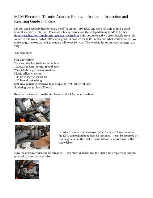
Remove duct work from the air cleaner to the TA connection boot<br />
In order to remove the crossover pipe, the hose clamp on top of<br />
the <strong>ETA</strong> connection boot must be loosened. It can be accessed by<br />
reaching in under the intake manifold from the front with a flat<br />
screwdriver.<br />
Now the crossover tube can be removed. Remember to disconnect the intake air temp sensor prior to<br />
removal of the crossover tube.
Next, remove the air resonance valve by removing the four Allen screws. Two will be under rubber<br />
plugs, simply pull the plugs out to access the screws. Unplug the harness connector very carefully as<br />
they can become brittle with age<br />
Air resonance valve<br />
<strong>ETA</strong> Boot, remove in the next step<br />
Now loosen the bottom clamp on the bottom of the <strong>ETA</strong> boot and remove the boot. You may have to<br />
pry on it, wiggle it until you discover the correct combination of four letter words to get it to come<br />
loose.<br />
Next, remove the four bolts holding the <strong>ETA</strong> to the intake manifold<br />
Remove these bolts<br />
Now disconnect the main wiring harness and remove the two 10mm nuts attaching the <strong>ETA</strong> harness to<br />
the engine.<br />
Remove this nut and one on the bottom of the bracket<br />
Unclip and unplug this connection<br />
Now slide the unbolted and unplugged <strong>ETA</strong> towards the front of the engine and unhook the throttle<br />
return spring.<br />
Next unclip the ball connector on the throttle linkage. The connection should release with a firm<br />
straight pull.<br />
With everything disconnected, you can slide the <strong>ETA</strong> towards the front of the engine and maneuver it<br />
out through the hole opened up when the air resonance valve was removed.
Now, clean up the <strong>ETA</strong> with carb cleaner or throttle body cleaner inside and out.<br />
Cut a slit ~2-3” long in the sheathing covering the wires. Open the slit to inspect the insulation on the<br />
wires. If there is any evidence of cracking or flaking, you will need to rewire the unit.<br />
Plastic filler cords<br />
If your insulation inspection shows cracked or missing insulation, silt the rubber sheath from the wiring<br />
harness connector up to about 1”-2” from the <strong>ETA</strong> body. Cut the sheath completely away from the<br />
connector, taking care not to cut any of the wires inside yet. Inside the sheath you will find eleven<br />
wires and several plastic filler cords. Go ahead and pull the fillers out, their removal will allow the<br />
replacement of the other wires to proceed easier.<br />
Using a #20 Torx bit with a center hole, remove the 4 bolts holding the cover on the end where the wire<br />
bundle enters the <strong>ETA</strong>. Once the 4 screws are removed, the cover can be pried off with a thin flat blade<br />
screwdriver. Note there is an anti tamper post that will break as the cover is removed. Don't worry as<br />
this repair will constitute tampering.<br />
Remove the two screws holding the circuit board in place and gently pull the circuit board out while<br />
pushing the wires through the sheath to create enough room to solder in the new wires<br />
The next step involves cutting open the harness connector. We used a razor saw followed by a utility<br />
knife, but it can be done with a utility knife alone. Cut along the mold parting lines on the sides and for<br />
the top, cut between the 1 and 4 in the first three digits of the molded in part number. Once the cuts are
completed, the cut section can be pried loose.<br />
Unfortunately, the pin holding portion of this connector does not seem to be removable, so the new<br />
wires will have to be soldered to the old ones.<br />
Pick one wire and one wire only and cut it a few inches from the connector.<br />
It is advisable to run a length of heat shrink tubing along the old wire down into the pin recess in the<br />
connector to eliminate any possibility of a short circuit inside the connector housing. It is easier to get<br />
the heat shrink tubing into the pin recess if the end is preshrunk for about 1/4” prior to placing it over<br />
the wire.<br />
1/8” heat shrink tubing pushed into the pin recess then shrunk in place.<br />
Match the conductor size of the wire you just cut with the closest conductor size in your replacement<br />
set. The bulk of the wires in the <strong>ETA</strong> are 22 gauge, but two appear to be 18 and three seem to be 20 ga.<br />
On the actuator end, carefully determine which wire you just cut by pulling gently on each wire at the<br />
circuit board. When you are certain of the correct wire, unsolder it from the circuit board and remove it<br />
from the wire bundle. Pass the replacement wire through the hole in the <strong>ETA</strong> body and solder it to the<br />
board in place of the wire you just removed.<br />
Place a section of heat shrink tubing on the new wire and splice the other end of the wire to the repaired<br />
wire at the connector end, solder and shrink the tubing. Label each end of the wire with a label, a series<br />
of dots or stripes, etc so you can tell them apart if necessary at some later date. If you can cross<br />
reference your identification marks to the original wire color code so much the better.<br />
Repeat until all of the wires have been replaced and labeled.
Finish the job by wrapping the repaired <strong>ETA</strong> wire bundle with self amalgamating tape or high quality<br />
PVC electrical tape. Self amalgamating means that it will bond to itself over time making one<br />
continuous rubber tube. Cheap PVC tape gets slimy with age, but good quality PVC tape is not as bad.<br />
Reinstall on the car with a new gasket and enjoy!
![[Buying Guide] - W124 Performance](https://img.yumpu.com/51307820/1/190x245/buying-guide-w124-performance.jpg?quality=85)