SERVICE LETTER X9 - Jacobs Vehicle Systems
SERVICE LETTER X9 - Jacobs Vehicle Systems
SERVICE LETTER X9 - Jacobs Vehicle Systems

You also want an ePaper? Increase the reach of your titles
YUMPU automatically turns print PDFs into web optimized ePapers that Google loves.
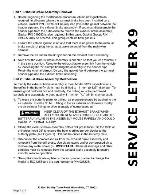
Part 1: Exhaust Brake Assembly Removal<br />
1. Before beginning the modification procedure, obtain new gaskets as<br />
required. In all cases where the exhaust brake has been installed on a<br />
vehicle, Gasket P/N 019590 will be required (this is the gasket between the<br />
header pipe and the exhaust brake assembly). If you must disassemble the<br />
header pipe from the turbo outlet to remove the exhaust brake assembly,<br />
Gasket P/N 019593 is also required. In this case, Gasket Group, P/N<br />
019665, may be ordered. This group contains both gaskets.<br />
2. Ensure the vehicle ignition is off and that there is no power to the exhaust<br />
brake circuit. Unplug the exhaust brake solenoid from the main wire<br />
harness.<br />
3. Remove the air line to the air cylinder on the exhaust brake assembly.<br />
4. Note how the exhaust brake assembly is oriented so that you can reinstall it<br />
in the same position. Remove the exhaust brake assembly from the vehicle<br />
by loosening the “V” clamps holding the assembly to the header pipe.<br />
Retain the original clamps. Discard the gasket found between the exhaust<br />
header pipe and the exhaust brake assembly.<br />
Part 2: Exhaust Brake Assembly Modification<br />
To modify the exhaust brake assembly to meet Model 3126B specifications,<br />
the orifice in the butterfly plate must be drilled to 11 mm (0.433”) diameter. To<br />
ensure good performance and reliability, the drilling must be performed<br />
carefully and accurately. A good quality 11 mm or 7 / 16 ” drill bit may be used.<br />
1. To close the butterfly plate for drilling, air pressure should be applied to the<br />
air cylinder. Install a ¼” NPT fitting in the air cylinder or otherwise modify<br />
the air cylinder fittings to allow a supply of compressed air.<br />
KEEP CLEAR OF THE EXHAUST BRAKE WHEN<br />
APPLYING OR REMOVING COMPRESSED AIR. THE<br />
BUTTERFLY VALVE IN THE ASSEMBLY MOVES RAPIDLY AND COULD<br />
CAUSE PERSONAL INJURY.<br />
1. Clamp the exhaust brake assembly onto a drill press table. Tilt the table or<br />
drill press head 26º to ensure the hole is drilled perpendicular to the<br />
butterfly plate (see Figure 1). Drill out the orifice in the butterfly plate.<br />
2. Disconnect the compressed air from the exhaust brake assembly and<br />
remove it from the drill press. Use clean towels and/or compressed air to<br />
remove any metal shavings. IMPORTANT! All metal shavings and other<br />
particles must be removed from the exhaust brake assembly to ensure<br />
smooth, reliable operation.<br />
3. Stamp the identification plate on the air cylinder bracket to change the<br />
Model to EX3126B and the part number to P/N 025223.<br />
<strong>SERVICE</strong> <strong>LETTER</strong> <strong>X9</strong><br />
Page 2 of 4<br />
22 East Dudley Town Road, Bloomfield, CT 06002<br />
www.jakebrake.com