SERVICE LETTER X9 - Jacobs Vehicle Systems
SERVICE LETTER X9 - Jacobs Vehicle Systems
SERVICE LETTER X9 - Jacobs Vehicle Systems

You also want an ePaper? Increase the reach of your titles
YUMPU automatically turns print PDFs into web optimized ePapers that Google loves.
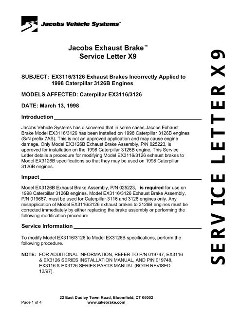
<strong>Jacobs</strong> Exhaust Brake <br />
Service Letter <strong>X9</strong><br />
SUBJECT: EX3116/3126 Exhaust Brakes Incorrectly Applied to<br />
1998 Caterpillar 3126B Engines<br />
MODELS AFFECTED: Caterpillar EX3116/3126<br />
DATE: March 13, 1998<br />
Introduction<br />
<strong>Jacobs</strong> <strong>Vehicle</strong> <strong>Systems</strong> has discovered that in some cases <strong>Jacobs</strong> Exhaust<br />
Brake Model EX3116/3126 has been installed on 1998 Caterpillar 3126B engines<br />
(S/N prefix 7AS). This is not an approved application and may cause engine<br />
damage. Only Model EX3126B Exhaust Brake Assembly, P/N 025223, is<br />
approved for installation on the 1998 Caterpillar 3126B engine. This Service<br />
Letter details a procedure for modifying Model EX3116/3126 exhaust brakes to<br />
Model EX3126B specifications so that they may be used on 1998 Caterpillar<br />
3126B engines.<br />
Impact<br />
Model EX3126B Exhaust Brake Assembly, P/N 025223, is required for use on<br />
1998 Caterpillar 3126B engines. Model EX3116/3126 Exhaust Brake Assembly,<br />
P/N 019667, must be used for Caterpillar 3116 and 3126 engines only. Any<br />
misapplication of Model EX3116/3126 exhaust brakes to 3126B engines must be<br />
corrected immediately by either replacing the brake assembly or performing the<br />
following modification procedure.<br />
Service Information<br />
To modify Model EX3116/3126 to Model EX3126B specifications, perform the<br />
following procedure.<br />
NOTE: FOR ADDITIONAL INFORMATION, REFER TO P/N 019747, EX3116<br />
& EX3126 SERIES INSTALLATION MANUAL, AND P/N 019748,<br />
EX3116 & EX3126 SERIES PARTS MANUAL (BOTH REVISED<br />
12/97).<br />
<strong>SERVICE</strong> <strong>LETTER</strong> <strong>X9</strong><br />
Page 1 of 4<br />
22 East Dudley Town Road, Bloomfield, CT 06002<br />
www.jakebrake.com
Part 1: Exhaust Brake Assembly Removal<br />
1. Before beginning the modification procedure, obtain new gaskets as<br />
required. In all cases where the exhaust brake has been installed on a<br />
vehicle, Gasket P/N 019590 will be required (this is the gasket between the<br />
header pipe and the exhaust brake assembly). If you must disassemble the<br />
header pipe from the turbo outlet to remove the exhaust brake assembly,<br />
Gasket P/N 019593 is also required. In this case, Gasket Group, P/N<br />
019665, may be ordered. This group contains both gaskets.<br />
2. Ensure the vehicle ignition is off and that there is no power to the exhaust<br />
brake circuit. Unplug the exhaust brake solenoid from the main wire<br />
harness.<br />
3. Remove the air line to the air cylinder on the exhaust brake assembly.<br />
4. Note how the exhaust brake assembly is oriented so that you can reinstall it<br />
in the same position. Remove the exhaust brake assembly from the vehicle<br />
by loosening the “V” clamps holding the assembly to the header pipe.<br />
Retain the original clamps. Discard the gasket found between the exhaust<br />
header pipe and the exhaust brake assembly.<br />
Part 2: Exhaust Brake Assembly Modification<br />
To modify the exhaust brake assembly to meet Model 3126B specifications,<br />
the orifice in the butterfly plate must be drilled to 11 mm (0.433”) diameter. To<br />
ensure good performance and reliability, the drilling must be performed<br />
carefully and accurately. A good quality 11 mm or 7 / 16 ” drill bit may be used.<br />
1. To close the butterfly plate for drilling, air pressure should be applied to the<br />
air cylinder. Install a ¼” NPT fitting in the air cylinder or otherwise modify<br />
the air cylinder fittings to allow a supply of compressed air.<br />
KEEP CLEAR OF THE EXHAUST BRAKE WHEN<br />
APPLYING OR REMOVING COMPRESSED AIR. THE<br />
BUTTERFLY VALVE IN THE ASSEMBLY MOVES RAPIDLY AND COULD<br />
CAUSE PERSONAL INJURY.<br />
1. Clamp the exhaust brake assembly onto a drill press table. Tilt the table or<br />
drill press head 26º to ensure the hole is drilled perpendicular to the<br />
butterfly plate (see Figure 1). Drill out the orifice in the butterfly plate.<br />
2. Disconnect the compressed air from the exhaust brake assembly and<br />
remove it from the drill press. Use clean towels and/or compressed air to<br />
remove any metal shavings. IMPORTANT! All metal shavings and other<br />
particles must be removed from the exhaust brake assembly to ensure<br />
smooth, reliable operation.<br />
3. Stamp the identification plate on the air cylinder bracket to change the<br />
Model to EX3126B and the part number to P/N 025223.<br />
<strong>SERVICE</strong> <strong>LETTER</strong> <strong>X9</strong><br />
Page 2 of 4<br />
22 East Dudley Town Road, Bloomfield, CT 06002<br />
www.jakebrake.com
Figure 1<br />
Part 3: Reinstall the Exhaust Brake<br />
1. Use a new Gasket, P/N 019590, when reinstalling the exhaust brake. Install<br />
this gasket on the upstream end of the exhaust brake assembly (the side<br />
pointing away from the air cylinder and bracket). Make sure that the gasket<br />
is installed on the locating pilot on the exhaust brake inlet.<br />
2. Attach the exhaust brake assembly to the header pipe, using the original<br />
“V” Clamp, P/N 019595. Tighten only enough to hold the parts loosely in<br />
place. Be sure to install the exhaust brake assembly so the air cylinder<br />
points away from the turbocharger.<br />
3. Position the exhaust brake assembly in its original orientation, or see the<br />
Installation Manual for recommended orientation. NOTE: Do not position<br />
the exhaust brake with the air cylinder above or below the exhaust pipe.<br />
4. Reattach the downstream exhaust pipe to the exhaust brake assembly<br />
using the other “V” Clamp, P/N 019595. No gasket is required between the<br />
exhaust brake and this section of pipe.<br />
5. Align and support all components as required. Tighten all “V” clamps to 70 -<br />
80 lb-in. (8-9 N•m).<br />
6. Reinstall the vehicle air supply to the air cylinder, using Teflon® thread<br />
sealing tape where required on pipe fittings.<br />
7. Reconnect the solenoid to the main wire harness.<br />
8. Test the exhaust brake for proper operation. Be sure to check for leaks in<br />
the system when the exhaust brake is operated. Any leaks must be<br />
corrected or performance will be reduced.<br />
<strong>SERVICE</strong> <strong>LETTER</strong> <strong>X9</strong><br />
Page 3 of 4<br />
22 East Dudley Town Road, Bloomfield, CT 06002<br />
www.jakebrake.com
Warranty Information<br />
This information is provided by <strong>Jacobs</strong> <strong>Vehicle</strong> <strong>Systems</strong> for informational<br />
purposes only. Any application of Model EX3116/3126 to Caterpillar Model 3126B<br />
engines is an unapproved application. As stated in the product warranty<br />
statement, <strong>Jacobs</strong> <strong>Vehicle</strong> <strong>Systems</strong> is not responsible for damage to the exhaust<br />
brake or components, engine or vehicle resulting from unapproved application of<br />
its products. In addition, <strong>Jacobs</strong> <strong>Vehicle</strong> <strong>Systems</strong> is not responsible for parts,<br />
labor, or other costs associated with modifications required due to misapplication<br />
of the exhaust brake or its components.<br />
No <strong>Jacobs</strong> products are subject to campaign by <strong>Jacobs</strong> as a result of this<br />
information.<br />
<strong>SERVICE</strong> <strong>LETTER</strong> <strong>X9</strong><br />
Page 4 of 4<br />
22 East Dudley Town Road, Bloomfield, CT 06002<br />
www.jakebrake.com