HBL - LED Highbay Installation Instruction Sheet - Hubbell Industrial ...
HBL - LED Highbay Installation Instruction Sheet - Hubbell Industrial ...
HBL - LED Highbay Installation Instruction Sheet - Hubbell Industrial ...

You also want an ePaper? Increase the reach of your titles
YUMPU automatically turns print PDFs into web optimized ePapers that Google loves.
<strong>HBL</strong> – INDUSTRIAL <strong>LED</strong> HIGHBAY<br />
INSTALLATION INSTRUCTIONS<br />
SEE WARNING ON CARTON<br />
GENERAL INFORMATION, CONDUIT MOUNT:<br />
• All 12” (304.8 mm) minimum supply wire outside of conduit.<br />
• Fixture housing conduit threads are 3/4-14 NPS.<br />
• Use a waterproof pipe joint compound (by others) for all entries into<br />
housing.<br />
• Plug all unused entries into housing (if applicable).<br />
• Minimum mounting distance from the ceiling to the top surface of<br />
the fixture to be two feet (24”).<br />
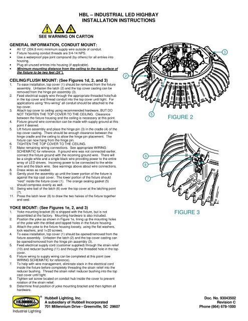
CEILING/FLUSH MOUNT: (See Figures 1d, 2, and 3)<br />
1. To ease installation, top cover (1) should be removed from the fixture<br />
assembly. Unfasten the latch (2) and the top cover casting can be<br />
removed from the hinge pin assembly (3).<br />
2. Feed electrical supply wire through the appropriate threaded hole/hub<br />
in the top cover and thread conduit into the top cover until tight. For<br />
applications using “thru-wiring” all conduit should be attached to the<br />
top cover.<br />
3. Attach top cover to ceiling using recommended hardware, BUT DO<br />
NOT TIGHTEN THE TOP COVER TO THE CEILING. Clearance<br />
between the fixture housing and the ceiling is necessary at this point.<br />
4. Fixture ground wire connection can be made with supply ground at this<br />
point if desired.<br />
5. Lift fixture assembly and place the hinge pin (3) in the cradle (4) of the<br />
top cover casting. There should be enough clearance between the<br />
hinge cradle and the ceiling to allow the hinge pin placement. The<br />
fixture can now hang from the hinge pin.<br />
6. TIGHTEN THE TOP COVER TO THE CEILING.<br />
7. Make remaining wiring connections. See appropriate WIRING<br />
SCHEMATIC for reference. If ground wire was not connected earlier,<br />
connect the fixture ground with the incoming ground wire. There will<br />
be a single white and a single black wire providing power to the entire<br />
array of <strong>LED</strong> drivers. Incoming power to be connected to the white<br />
wire and the black wire. See warnings above about wire connections.<br />
8. Dress wires as needed.<br />
9. Gently pivot the assembly up until the lower portion of the fixture is<br />
against the top cast cover. The lower portion of the fixture should<br />
“nest” inside the fixture cover (1). The orange sealing gasket (5)<br />
should compress evenly as well.<br />
10. Swing wire bail of the latch (6) over the top cover at the latching point<br />
(7).<br />
11. Press the latch lever (8) to draw the two halves of the fixture together<br />
and seal.<br />
2<br />
6<br />
8<br />
7<br />
5<br />
FIGURE 2<br />
3<br />
YOKE MOUNT: (See Figures 1e, 2, and 3)<br />
1. Yoke mounting bracket (9) is shipped with the fixture, but is not<br />
assembled at the factory. Mounting hardware is also included.<br />
2. Position the yoke as shown in Figure 1e, lining up the mounting holes<br />
of the yoke with the drilled and tapped holes in the fixture housing.<br />
3. Attach the yoke to the fixture housing loosely, using the flat washers,<br />
lock washers, and ¼-20 screws.<br />
4. To ease installation, top cover (1) should be opened/removed from the<br />
fixture assembly. Unfasten the latch (2) and the top cover casting can<br />
be opened/removed from the hinge pin assembly (3).<br />
5. Feed electrical supply cord (customer supplied) through the strain relief<br />
(10) and reducer bushing (11) and through the threaded hole in the top<br />
cover.<br />
6. Fixture wiring to supply wiring can be completed at this point (see<br />
WIRING SCHEMATIC for reference).<br />
7. To help with wire management, eliminate slack in the electrical cord<br />
inside the fixture before completely threading the strain relief into the<br />
reducer bushing. Thread the strain relief /reducer bushing into the top<br />
cast cover until tight.<br />
8. Tighten set screw located on conduit hub inside the cover to prevent<br />
rotation of the strain relief.<br />
9. Determine final position of yoke mounting bracket and then tighten all<br />
hardware.<br />
FIGURE 3<br />
<strong>Industrial</strong> Lighting<br />
®<br />
<strong>Hubbell</strong> Lighting, Inc. Doc. No. 93043502<br />
A subsidiary of <strong>Hubbell</strong> Incorporated<br />
Revision C<br />
701 Millennium Drive • Greenville, SC 29607 Phone (864) 678-1000