Use of Ground-Based LiDAR - Geotechnical Extreme Events ...
Use of Ground-Based LiDAR - Geotechnical Extreme Events ...
Use of Ground-Based LiDAR - Geotechnical Extreme Events ...

You also want an ePaper? Increase the reach of your titles
YUMPU automatically turns print PDFs into web optimized ePapers that Google loves.
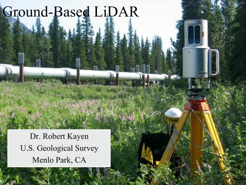
<strong>Ground</strong>-<strong>Based</strong> <strong>LiDAR</strong><br />
Dr. Robert Kayen<br />
U.S. Geological Survey<br />
Menlo Park, CA
The Reconnaissance Problem:<br />
We want to collect and archive highly<br />
detailed, accurate spatial measurements<br />
<strong>of</strong> damaged ground and structures, and<br />
do this rapidly, with limited budget<br />
Solution: Tripod-mounted <strong>LiDAR</strong>
<strong>Ground</strong>-<strong>Based</strong> <strong>LiDAR</strong><br />
• <strong>LiDAR</strong> (Light Detection And Ranging)<br />
QuickTime and a<br />
TIFF (Uncompressed) decompressor<br />
are needed to see this picture.<br />
Distance = (Speed <strong>of</strong> Light x Time <strong>of</strong> Flight) / 2<br />
• Portable & light tripod-mounted systems<br />
• Fixed or Rotating laser-line scanner systems<br />
• Produces 3-D target positions at up to 500k<br />
positions/minute<br />
• Range: Up To 1 kilometer around Tripod<br />
under optimal atmospheric conditions
<strong>LiDAR</strong> & GEER: Bringing damage<br />
ground and structural morphologies<br />
back to the lab for analysis, and as a<br />
permanent record <strong>of</strong> event effects.<br />
• Rapid data collection <strong>of</strong> damaged terrain.<br />
• Ultra-high accuracy terrain models for deformation<br />
calculations and change detection .<br />
• Archive-quality spatial models <strong>of</strong> damage.<br />
• 3-D spatial visuals and fly-through videos for<br />
engineering analysis and public outreach.
USGS-GD Unit:<br />
Riegl z210i<br />
USGS-WRD Unit:<br />
Optech ILRIS-3D
<strong>LiDAR</strong> Systems at the USGS<br />
Riegl z210i<br />
General Purpose<br />
Mapper:<br />
• 700m+ Range<br />
• Max. X,Y,Z<br />
Accuracy 0.9 cm<br />
• Targets: 5.6M in<br />
11 minutes<br />
• Scan window: 80°<br />
by 336°<br />
USGS-Geologic Division<br />
System<br />
OpTech ILRIS-3D<br />
Narrow window<br />
High-Res Mapper<br />
• 300m+ Range<br />
• Max. X,Y,Z<br />
Accuracy 0.3-0.4<br />
cm<br />
• Targets: 1.8M in<br />
15 minutes<br />
• Fixed window:<br />
40° by 40°<br />
USGS-Water Resources<br />
Division System
Denali Fault <strong>of</strong>fset at<br />
Trans Alaska Pipeline, 7/2004:<br />
Single Riegl z210i Scan range 580m
<strong>LiDAR</strong> Systems at the USGS<br />
Riegl z210i<br />
General Purpose<br />
Mapper:<br />
• 700m Range<br />
• Max. X,Y,Z<br />
Accuracy 0.9 cm<br />
• Target points:<br />
5.6M in 11 minutes<br />
• Scan window: 80°<br />
by 336°<br />
USGS-GD System<br />
OpTech ILRIS-3D<br />
Narrow window<br />
High-Res Mapper<br />
• 300m+ Range<br />
• Max. X,Y,Z<br />
Accuracy 0.3-0.4<br />
cm<br />
• Target Points:<br />
1.8M in 15 minutes<br />
• Fixed window:<br />
40° by 40°<br />
USGS-WRD System
Traditional postslip<br />
survey marks<br />
Point Resolution<br />
Spacing : ~2mm<br />
near tripod<br />
with 9mm 3-D resolution<br />
Parkfield 10/4/04<br />
Fissure<br />
~30 cm
Sub-cm 3-D spatial<br />
deformation measurements <strong>of</strong><br />
minor or significant damage<br />
at distances up to 700-1000m<br />
Minor<br />
Fissures<br />
Parkfield 10/4/2004
<strong>LiDAR</strong> Data Processing<br />
Riegl z210i<br />
Single or Multiple<br />
scans.<br />
Merge point cloud<br />
data with I-Site3D<br />
Triangulated<br />
surface (TIN) for<br />
measurement and<br />
change detection<br />
using I-Site3D<br />
USGS-GD System<br />
OpTech ILRIS-3D<br />
Multiple scans to<br />
expand scan<br />
window & eliminate<br />
shadow zones.<br />
Merge point cloud<br />
data, produce<br />
triangulated<br />
surface (TIN) with<br />
PolyWorks.<br />
USGS-WRD System
10 m<br />
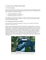
Merging scans to eliminate<br />
shadow zones<br />
Example: single scan <strong>of</strong> 50-<br />
60 cm Denali Fault scarp.
Denali Fault: Merge <strong>of</strong> 2 scans to produce fewer<br />
shadow (no data) zones in surface model. High<br />
quality DGPS geo-referencing needed for merge.
Denali Fault: Merging <strong>of</strong> 8 scans to produce a largely<br />
shadow free surface model <strong>of</strong> rupture
TIN surfaces ready for change detection analysis<br />
Collins & Sitar, 2003, AEG Ann. Mtg.
Summary<br />
• GEER-EERI-USGS can utilize ground-based<br />
<strong>LiDAR</strong> to collect damage morphology data at<br />
speeds, accuracies, and range that was previously<br />
unimaginable in earthquake reconnaissance.<br />
• These permanently archived terrain models will<br />
vastly improve controls on empirical deformation<br />
studies and allow researchers decades later to<br />
virtually-revisit damage sites.
<strong>Ground</strong>-<strong>Based</strong> <strong>LiDAR</strong><br />
Dr. Robert Kayen<br />
U.S. Geological Survey<br />
Menlo Park, CA