Declaration of Conformity - Csidesigns.com
Declaration of Conformity - Csidesigns.com
Declaration of Conformity - Csidesigns.com
Create successful ePaper yourself
Turn your PDF publications into a flip-book with our unique Google optimized e-Paper software.
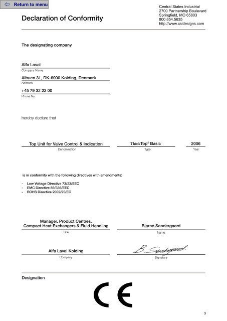
<strong>Declaration</strong> <strong>of</strong> <strong>Conformity</strong><br />
Central States Industrial<br />
2700 Partnership Boulevard<br />
Springfield, MO 65803<br />
800.654.5635<br />
http://www.csidesigns.<strong>com</strong><br />
The designating <strong>com</strong>pany<br />
Alfa Laval<br />
Company Name<br />
Albuen 31, DK-6000 Kolding, Denmark<br />
Address<br />
+45 79 32 22 00<br />
Phone No.<br />
hereby declare that<br />
Top Unit for Valve Control & Indication<br />
ThinkTop ® Basic 2006<br />
Denomination Type Year<br />
is in conformity with the following directives with amendments:<br />
- Low Voltage Directive 73/23/EEC<br />
- EMC Directive 89/336/EEC<br />
- ROHS Directive 2002/95/EC<br />
Manager, Product Centres,<br />
Compact Heat Exchangers & Fluid Handling<br />
Title<br />
Bjarne Søndergaard<br />
Name<br />
Alfa Laval Kolding<br />
Company<br />
Signature<br />
Designation<br />
3
Central States Industrial<br />
2700 Partnership Boulevard<br />
Springfield, MO 65803<br />
800.654.5635<br />
http://www.csidesigns.<strong>com</strong><br />
Table <strong>of</strong> contents<br />
The information contained herein is correct at the time <strong>of</strong> issue but may be subject to change without prior notice.<br />
1. Safety .................................................................................................... 6<br />
1.1 Important information ....................................................................... 6<br />
1.2 Warning signs ................................................................................... 6<br />
1.3 Safety precautions ............................................................................ 6<br />
2. General information................................................................................7<br />
2.1 Digital in general ............................................................................... 7<br />
3. Technical specifications ....................................................................... 8<br />
3.1 ThinkTop ® Basic, PLC 10-30 VDC interface ..................................... 8<br />
4. Installation ........................................................................................... 11<br />
4.1 Installation on air actuators ............................................................. 11<br />
4.2 Installation on Series 700 valves ..................................................... 14<br />
4.3 Air connections .............................................................................. 15<br />
4.4 Electrical connection ...................................................................... 16<br />
5. Setup diagram .................................................................................... 17<br />
5.1 ThinkTop ® Basic setup utilising IR keypad ..................................... 17<br />
6. Maintenance ....................................................................................... 18<br />
6.1 Dismantling <strong>of</strong> ThinkTop ® Basic .................................................... 18<br />
6.2 Assembly <strong>of</strong> ThinkTop ® Basic ....................................................... 20<br />
6.3 Dismantling and assembly <strong>of</strong> Series 700 Valves ............................. 22<br />
7. Parts list .............................................................................................. 24<br />
7.1 ThinkTop ® Basic Digital 10-30 VDC PNP/NPN ............................... 24<br />
7.2 ThinkTop ® Basic Series 700 valves ................................................ 26<br />
5
1.1 Important information<br />
1.2 Warning signs<br />
1.3 Safety precautions<br />
Central States Industrial<br />
2700 Partnership Boulevard<br />
Springfield, MO 65803<br />
800.654.5635<br />
http://www.csidesigns.<strong>com</strong><br />
Unsafe practices and other important information are emphasized in this manual.<br />
Warnings are emphasized by means <strong>of</strong> special signs.<br />
All warnings in the manual are summarized on this page.<br />
Pay special attention to the instructions below so that severe personal injury or damage to the top unit are avoided.<br />
1. Safety<br />
Always read the manual before using the top unit!<br />
WARNING!<br />
Indicates that special procedures must be followed to avoid severe personal injury.<br />
CAUTION!<br />
Indicates that special procedures must be followed to avoid damage to the ThinkTop ® Basic.<br />
NOTE!<br />
Indicates important information to simplify or clarify practices.<br />
General warning:<br />
Dangerous electrical voltage:<br />
Caustic agents:<br />
Installation<br />
- Always observe the technical specifications (see chapter 3).<br />
- Never install the ThinkTop ® Basic before valve or relay is in a safe position.<br />
- If welding close to the ThinkTop ® Basic: Always earth close to the welding area.<br />
- Disconnect the ThinkTop ® Basic.<br />
- Always have the ThinkTop ® Basic electrically connected by authorized personnel.<br />
Maintenance<br />
- Always read the technical specifications thoroughly (see chapter 3).<br />
- Always fit the seals between valve and ThinkTop ® Basic correctly.<br />
- Never service the ThinkTop ® Basic before valve or relay is in a safe position.<br />
- Never service the ThinkTop ® Basic with valve/actuator under pressure.<br />
- Never clean the ThinkTop ® Basic with high pressure cleaning equipment.<br />
- Never use cleaning agents when cleaning the ThinkTop ® Basic.<br />
Check with cleaning agent supplier.<br />
6
2. General information<br />
Central States Industrial<br />
2700 Partnership Boulevard<br />
Springfield, MO 65803<br />
800.654.5635<br />
2.1 Digital in general<br />
http://www.csidesigns.<strong>com</strong><br />
The ThinkTop ® Basic is designed to ensure optimum valve control in conjunction with Alfa Laval valves and it is <strong>com</strong>patible<br />
with most PLC systems (Programmable Logic Controllers maker with PNP/NPN interface).<br />
The ThinkTop ® Basic can be equipped with 0-3 solenoid valves. The solenoids are electrically controlled by the Digital PLC<br />
and when activated the <strong>com</strong>pressed air is activating the air actuator. All solenoids have built-in throttle function on both air<br />
inlet and outlet which means that it is possible to control the opening and closing time <strong>of</strong> the air actuator. The solenoids are<br />
also equipped with a manual hold override.<br />
Visual LED lights are constantly indicating the status <strong>of</strong> the unit: Valve positions, solenoid activated, setup and local fault<br />
indication etc.<br />
The ThinkTop ® Basic is characterized by a simple and modular design. It is exchangeable and is prepared for upgrading.<br />
7
3.1 ThinkTop ® Basic, PLC 10-30 VDC interface<br />
3. Technical specifications<br />
3.1 “No Touch” sensor system<br />
PLC,<br />
DC feedback<br />
Central States Industrial<br />
2700 Partnership Boulevard<br />
Springfield, MO 65803<br />
800.654.5635<br />
http://www.csidesigns.<strong>com</strong><br />
Type: Alfa Laval “No Touch” System<br />
For wire connections: See section 4.5 “Electrical connection, internal”.<br />
Features<br />
• Easy and simple set-up, using locally pushbuttons<br />
• No manual sensor adjustments at all<br />
• No sensor “movements” due to vibrations<br />
• Modular and hygienic design with exchangeabilities<br />
• Clear LED’s for visual status indication<br />
• Set-up parameters saved in case <strong>of</strong> power failure<br />
Sensor system<br />
Unique “No Touch” sensor system without any mechanical sensor adjustments. A magnet is mounted on the valve stem and<br />
the magnetic field (axial) is detected by sensor chips inside the sensor unit. The measuring angle from each chip is used to<br />
locate the current position <strong>of</strong> the valve stem with an accuracy <strong>of</strong> ± 0.1mm. Note that the distance to the magnet can be 5<br />
mm ± 3 mm.<br />
Feedback signals<br />
The sensor system can be used for 2 digital PNP/NPN feedback signals. Selection <strong>of</strong> PNP or NPN is done by a jumper.<br />
Two <strong>of</strong> the feedback signals can be used for external sensors if necessary.<br />
Output signals from the sensor unit to the connected digital interface (PLC).<br />
Nominal voltage:<br />
Same as connected to the ThinkTop ® Basic.<br />
Load current:<br />
50 mA typical, 100 mA max.<br />
Voltage drop:<br />
Typical 3 V 50 mA.<br />
Power supply - DC:<br />
The ThinkTop ® Basic is designed to be part <strong>of</strong> the PLC’s Input/Output (I/O) system. It should be supplied from the same<br />
protected power supply as the other I/O devises. The I/O power supply should not be used for other kinds <strong>of</strong> loads.<br />
The unit is reverse polarity and short circuit protected. The power supply must meet the requirements <strong>of</strong> EN 61131-2.<br />
Supply voltage:<br />
10 - 30 VDC.<br />
Supply voltage nominal: 24 VDC (+20%, -15%) - pr. EN 61131-2.<br />
Max ripple:<br />
5% <strong>of</strong> nominal supply voltage.<br />
Supply voltage absolute max.: 30 VDC.<br />
Supply voltage absolute min.: 10 VDC.<br />
Supply current*):<br />
Max. 45 mA (for sensor unit alone, excluding solenoids)<br />
*) The initial current during power-on is higher. The actual shape <strong>of</strong> the current pulse depends on the power supply used.<br />
Typical values are 150 mA RMS during 13 ms (regulated PS) to 330 mA RMS during 8 ms (unregulated PS).<br />
8
3. Technical specifications 3.1 ThinkTop ® Basic, PLC 8-30 VDC interface<br />
The fulfilling <strong>of</strong> the UL requirements in UL 508 requires that the unit is supplied by an isolating source <strong>com</strong>plying with the<br />
requirements for class 2 power units (UL 1310) or class 2 and 3 transformers (UL 1585).<br />
Sensor detection system:<br />
Sensor accuracy:<br />
Tolerance band:<br />
Distance to magnet:<br />
Stroke length:<br />
+/- 0,1 mm.<br />
+/- 5 mm.<br />
5 +/- 3 mm.<br />
0.1 - 80 mm.<br />
PNP/NPN polarity<br />
PNP (sourcing) or NPN (sinking) function is selected by a jumper in terminals 9 and 10. Jumper present = PNP (standard).<br />
If changing to NPN remove the jumper and make a power recycle. A power recycle is always required when changing this<br />
function.<br />
Typical power consumption ThinkTop ® Basic:<br />
Test conditions = One ThinkTop ® Basic connected and 1 feedback active (on) and:<br />
No solenoids on Supply voltage 24 VDC 30 mA<br />
1 solenoid active Supply voltage 24 VDC 75 mA<br />
2 solenoids active Supply voltage 24 VDC 120 mA<br />
3 solenoids active Supply voltage 24 VDC 165 mA<br />
Note! “Power-on” current is higher - See power supply - DC.<br />
ThinkTop ® Basic visual indications<br />
LED indications<br />
LED A A = “Energized” (Yellow)<br />
B = “Set-up/fault”<br />
(red)<br />
LED B C = “Solenoids” (Yellow)<br />
D = “De-energized”<br />
(Green)<br />
LED C<br />
LED D<br />
Central States Industrial<br />
2700 Partnership Boulevard<br />
Springfield, MO 65803<br />
800.654.5635<br />
http://www.csidesigns.<strong>com</strong><br />
9
3. Technical specifications 3.1 ThinkTop ® Basic, PLC 8-30 VDC interface<br />
Solenoid Valves:<br />
0 to 3 solenoid valves in each unit possible.<br />
Type:<br />
3/2 or 5/2 port (only possible with one 5/2 port).<br />
Air supply:<br />
300-900 kPa (3-9 bar).<br />
Filtered air, max. particles or dirt:<br />
0.01 mm.<br />
Max. flow:<br />
180 l/min.<br />
Max. oil content:<br />
1.0 ppm.<br />
Max. water content:<br />
0.0075 kg/kg air.<br />
Throughput:<br />
ø2.5 mm.<br />
Manual hold override:<br />
Yes.<br />
External air tube connection:<br />
øø 6 mm or ¼” (select when ordering).<br />
Nominal voltage:<br />
24 VDC.<br />
Nominal power: 1.0 W.<br />
Silencer/filter **):<br />
Connection possible via ø 6 mm or ¼”.<br />
Materials<br />
Plastic parts:<br />
Nylon PA 6, reinforced.<br />
Steel parts: Stainless steel AISI 304 and 316.<br />
Air fitting:<br />
Special coated brass (FDA approved).<br />
Seals:<br />
Nitrile (NBR).<br />
**) Filter re<strong>com</strong>mended in tropical regions.<br />
Micro environment demand specifications<br />
Temperature<br />
Working: -20°C to +85°C IEC 68-2-1/2<br />
Storage: -40°C to +85°C IEC 68-2-1/2<br />
Temperature change: -25°C to +70°C IEC 68-2-14<br />
Vibration 10-55 Hz, 0.7 mm IEC 68-2-6<br />
55-500 Hz, 10g<br />
3 x 30 min, 1 octave/min<br />
Drop test IEC 68-2-32<br />
Humidity<br />
Constant humidity: +40°C, 21 days, 93% R.H. IEC 60068-2-78<br />
Cyclic humidity:<br />
+25°C/+55°C<br />
12 cycles<br />
(working)<br />
93% R.H.<br />
Protection class IP66 and IP67 EN 60529<br />
Input treshold<br />
Voltage/current: Type 1 input requirements EN 61131-2<br />
Solenoid signals<br />
Isolation voltage (1000 + 2 x 117) VAC rms/1 min EN 61131-2<br />
EMC Directive 89/336/EEC EN 61000-6-3, EN 61000-6-2<br />
UL/CSA<br />
10-30 VDC/AC, Class 2 input,<br />
45 mA max. output UL 508-E203255<br />
10<br />
Central States Industrial<br />
2700 Partnership Boulevard<br />
Springfield, MO 65803<br />
800.654.5635<br />
http://www.csidesigns.<strong>com</strong>
4.1 Installation on air actuators<br />
Central States Industrial<br />
2700 Partnership Boulevard<br />
Springfield, MO 65803<br />
800.654.5635<br />
http://www.csidesigns.<strong>com</strong><br />
4. Installation<br />
Step 1<br />
- Always read the technical specifications thoroughly (see chapter 3).<br />
- Always have the ThinkTop ® Basic electrically connected by authorized personnel.<br />
- Always install the ThinkTop ® Basic before valve or relay is in a safe position.<br />
Step 2<br />
1. Fit the air fittings on actuator if not mounted.<br />
2. Fit the activator stem (magnet) and tighten carefully<br />
with a spanner.<br />
SRC/ARC only<br />
Step 3<br />
1. Place the ThinkTop ® Basic on top <strong>of</strong> the actuator.<br />
2. Make sure X-ring is mounted.<br />
Step 4<br />
1. Ensure that the unit is correctly mounted by pressing<br />
down on top <strong>of</strong> the ThinkTop ® Basic.<br />
2. Tighten the two Allen screws carefully.<br />
3. Turn the actuator to have LEDs in a front view.<br />
NOTE!<br />
After a relevant period <strong>of</strong> time after installation<br />
(e.g. two weeks) it is re<strong>com</strong>mended to check<br />
that all connections are properly tightened.<br />
11
Central States Industrial<br />
2700 Partnership Boulevard<br />
4. Installation<br />
Springfield, MO 65803<br />
800.654.5635<br />
4.1 Installation on air actuators<br />
http://www.csidesigns.<strong>com</strong><br />
Step 5<br />
Fit the ø6 mm (1/4”) air tubes to ThinkTop ® Basic.<br />
(see drawing “Air connections” later in this chapter).<br />
Step 6<br />
Fit the air tubes to the actuator<br />
(see drawing “Air connections” later in this chapter).<br />
Step 7<br />
Untighten the four screws and pull <strong>of</strong>f cover <strong>of</strong> ThinkTop ® Basic.<br />
Step 8<br />
1. Install cable (if not present) through the cable gland.<br />
2. Connect the ThinkTop ® Basic electrically<br />
(see section 4.4 “Electrical connection, internal”).<br />
12
4.1 Installation on air actuators<br />
Central States Industrial<br />
2700 Partnership Boulevard<br />
Springfield, MO 65803<br />
800.654.5635<br />
http://www.csidesigns.<strong>com</strong><br />
4. Installation<br />
Step 9<br />
Make sure the cable gland is <strong>com</strong>pletely tightened.<br />
Step 10<br />
Set up the ThinkTop ® Basic (see chapter 5).<br />
NOTE!<br />
The unit can be set up with the cover installed by using the IR keypad.<br />
To energize the valve, use a separate air tube or be in radio contact with the control room.<br />
13
Central States Industrial<br />
2700 Partnership Boulevard<br />
4. Installation<br />
Springfield, MO 65803<br />
800.654.5635<br />
4.2 Installation on Series 700 valves<br />
http://www.csidesigns.<strong>com</strong><br />
Step 1<br />
1. Remove the cover by loosening the four cross recess<br />
screws.<br />
2. Separate the adapter from the base by loosening<br />
the three recess screws on top <strong>of</strong> the base.<br />
Installation on<br />
air actuators:<br />
Step 2<br />
1. Fit air fittings on actuator.<br />
2. Position packing retainer in recess on actuator top.<br />
3. Fit counter nut and indicator (magnet) on actuator rod.<br />
Engage approx. ¼” thread. Tighten counter nut and<br />
indicator with two wrenches.<br />
Step 3<br />
1. Place the two O-rings in the grooves in the bottom <strong>of</strong> the adapter.<br />
Then place the adapter on the actuator top. The small<br />
O-ring must be positioned over the air hole on the actuator.<br />
2. Fasten the adapter with the four 5/16” Allen screws.<br />
Step 4<br />
Mount the base on the adapter in the position needed<br />
(can be rotated 120° in both directions). Note that one <strong>of</strong> the screw<br />
towers on the adapter has a guide recess (see on drawing).<br />
<br />
14
4.3 Air connections<br />
Central States Industrial<br />
2700 Partnership Boulevard<br />
Springfield, MO 65803<br />
800.654.5635<br />
http://www.csidesigns.<strong>com</strong><br />
4. Installation<br />
Air out 1A<br />
Manual hold override<br />
Air exhaust<br />
Air out 1B (5/2 port<br />
solenoid valve only)<br />
1<br />
Solenoid valve<br />
Air out 2<br />
2<br />
Air out 3<br />
3<br />
Air in<br />
15
4.4 Electrical connection<br />
Central States Industrial<br />
2700 Partnership Boulevard<br />
Springfield, MO 65803<br />
800.654.5635<br />
http://www.csidesigns.<strong>com</strong><br />
4. Installation<br />
Electrical connections<br />
De-energized (PLC input)<br />
Energized (PLC input)<br />
Activation <strong>of</strong> solenoid # 1 (PLC output)<br />
Activation <strong>of</strong> solenoid # 2 (PLC output)<br />
Activation <strong>of</strong> solenoid # 3 (PLC output)<br />
Supply voltage sensor (+) 10-30 VDC<br />
Supply voltage sensor (0) 0 V<br />
Common supply solenoids<br />
PNP/NPN jumper*)<br />
PNP/NPN jumper*)<br />
Solenoid <strong>com</strong>mon, internal connection<br />
Solenoid # 1, internal connection<br />
Solenoid # 2, internal connection<br />
Solenoid # 3, internal connection<br />
A + D<br />
C<br />
D<br />
*) Jumper present = PNP. If changing the function a power recycle is necessary.<br />
The selection NPN/PNP is done by the jumper.<br />
Note! Remember to isolate wires that are not in use.<br />
16
5.1 ThinkTop ® Basic, setup<br />
Central States Industrial<br />
2700 Partnership Boulevard<br />
Springfield, MO 65803<br />
800.654.5635<br />
http://www.csidesigns.<strong>com</strong><br />
5. Setup diagram<br />
Timeout: A 30 second time-out is started as soon<br />
as any button(s) are released.<br />
If no button is pressed during the<br />
time-out period, go to normal condition<br />
(cancel & exit).<br />
Red LED: Active during set-up.<br />
- Flashing in step 1<br />
- Steady in all other steps.<br />
or during operations, error condition:<br />
- Steady showing hardware fault,<br />
magnet out <strong>of</strong> range.<br />
- Flashing showing s<strong>of</strong>tware fault<br />
“red” steady<br />
“green” flashing<br />
if de-energized<br />
position disabled<br />
“green” steady<br />
if de-energized<br />
position enabled<br />
“red” steady<br />
“yellow” flashing<br />
if energized<br />
position disabled<br />
“yellow” steady<br />
if energized<br />
position enabled<br />
“red” flashing<br />
Actuator in<br />
De-energized<br />
Position<br />
Actuator in<br />
Energized<br />
Position<br />
Step 1<br />
Step 2<br />
Step 3<br />
Accept Settings<br />
“I” Restart set-up<br />
sequence<br />
“II” Save & Exit<br />
“II”* Cancel & Exit,<br />
no changes accepted<br />
* Hold for 5 sec.<br />
Set De-energized Position<br />
“II” Store Position<br />
“I” Bypass<br />
“II”* Disable function<br />
* Hold for 5 sec.<br />
Set Energized Position<br />
“II” Store Position<br />
“I” Bypass<br />
“II”* Disable function<br />
* Hold for 5 sec.<br />
Quick set-up:<br />
Push: “I”, enter setup and wait until red LED flashes.<br />
Push: “I”, restart set-up.<br />
Actuator in De-energized position<br />
Push: “II”, store position<br />
Actuator in energized position<br />
Push: “II”, store position<br />
Push: “II”, when red LED is flashing (save & exit)<br />
Set-up done.<br />
17
6.1 Dismantling <strong>of</strong> ThinkTop ® Basic<br />
Central States Industrial<br />
2700 Partnership Boulevard<br />
Springfield, MO 65803<br />
800.654.5635<br />
http://www.csidesigns.<strong>com</strong><br />
6. Maintenance<br />
Study the instructions carefully.<br />
Handle scrap correctly.<br />
Always keep spare X-rings in stock.<br />
Step 1<br />
1. Remove the ThinkTop ® Basic from the actuator.<br />
2. Pull out X-ring (19) and replace it.<br />
Step 2<br />
1. Untighten the four screws.<br />
2. Pull <strong>of</strong>f cover <strong>of</strong> ThinkTop ® Basic.<br />
3. Remove X-ring (9).<br />
Step 3<br />
1. Untighten screws.<br />
2. Remove solenoid valves (up to three) and replace them<br />
with new ones.<br />
Step 4<br />
1. To dismantle the adapter (the lower part <strong>of</strong> the ThinkTop ® Basic ® )<br />
from base (the middle part), unscrew the three screws.<br />
2. Turn the lower part a little clockwise and pull.<br />
3. Replace adapter if necessary.<br />
4. Remove X-ring (16).<br />
Note:<br />
Turn banjo<br />
connection!<br />
18
Central States Industrial<br />
2700 Partnership Boulevard<br />
6. Maintenance<br />
Springfield, MO 65803<br />
800.654.5635<br />
6.1 Dismantling <strong>of</strong> ThinkTop ® Basic<br />
http://www.csidesigns.<strong>com</strong><br />
Study the instructions carefully.<br />
Handle scrap correctly.<br />
Always keep spare X-rings in stock.<br />
Step 5<br />
To remove the sensor unit untighten screw and pull out the<br />
sensor unit.<br />
19
6.2 Assembly <strong>of</strong> ThinkTop ® Basic<br />
Study the instructions carefully.<br />
Handle scrap correctly.<br />
Always keep spare X-rings in stock.<br />
Central States Industrial<br />
2700 Partnership Boulevard<br />
Springfield, MO 65803<br />
800.654.5635<br />
http://www.csidesigns.<strong>com</strong><br />
6. Maintenance<br />
Step 1<br />
Place sensor unit in base and tighten screw (torque: 1 Nm).<br />
Step 2<br />
1. Assemble base with adapter by turning adapter slightly<br />
anticlockwise and tighten the three screws (1.9 Nm).<br />
2. Replace X-ring (16).<br />
CAUTION!<br />
Do NOT twist the X-ring in the groove!<br />
The X-ring is not square; The highest (h) part<br />
must be placed as fig.<br />
Note:<br />
Turn banjo<br />
connection!<br />
Step 3<br />
1. Replace solenoid valves (up to three) with new ones.<br />
2. Tighten screws (0.2 Nm).<br />
Step 4<br />
1. Replace X-ring (9).<br />
2. Replace cover <strong>of</strong> ThinkTop ® Basic and tighten the three screws (0.6 Nm).<br />
CAUTION!<br />
Do NOT twist the X-ring in the groove!<br />
The X-ring is not square; The highest (h) part<br />
must be placed as fig.<br />
20
Central States Industrial<br />
2700 Partnership Boulevard<br />
6. Maintenance<br />
Springfield, MO 65803<br />
800.654.5635<br />
6.2 Assembly <strong>of</strong> ThinkTop ® Basic<br />
http://www.csidesigns.<strong>com</strong><br />
Study the instructions carefully.<br />
Handle scrap correctly.<br />
Always keep spare X-rings in stock.<br />
Step 5<br />
1. Replace X-ring (19).<br />
2. Mount ThinkTop ® Basic on actuator.<br />
21
6.3 Dismantling and assembly <strong>of</strong> Series 700 Valves<br />
Central States Industrial<br />
2700 Partnership Boulevard<br />
Springfield, MO 65803<br />
6. Maintenance<br />
800.654.5635<br />
http://www.csidesigns.<strong>com</strong><br />
Study the instructions carefully.<br />
Handle scrap correctly.<br />
Always keep spare X-rings in stock.<br />
Step 1<br />
1. Remove the cover by loosening the four cross recess screws.<br />
2. Separate the adapter from the base by loosening the<br />
three recess screws on top <strong>of</strong> the base.<br />
Installation on air<br />
actuators:<br />
Step 2<br />
1. Fit air fittings on actuator.<br />
2. Position packing retainer in recess on actuator top.<br />
3. Fit counter nut and indicator (magnet) on actuator rod.<br />
Engage approx. 1/4” thread. Tighten counter nut and<br />
indicator with two wrenches.<br />
Step 3<br />
1. Place the two O-rings in the grooves in the bottom <strong>of</strong> the adapter.<br />
Then place the adapter on the actuator top. The small O-ring must<br />
be positioned over the air hole on the actuator.<br />
2. Fasten the adapter with the four 5/16” Allen screws.<br />
Step 4<br />
- Remove x-rings (9) and (16).<br />
- Replace with new ones.<br />
- Mount the base on the adapter in the position needed (can be rotated 120°<br />
in both directions). Note that one <strong>of</strong> the screw towers on the adapter<br />
has a guide recess (see on drawing).<br />
CAUTION!<br />
Do NOT twist the X-ring in the groove!<br />
The X-ring is not square; The highest (h) part<br />
must be placed as fig.<br />
<br />
22
Central States Industrial<br />
2700 Partnership Boulevard<br />
Springfield, MO 65803<br />
800.654.5635<br />
http://www.csidesigns.<strong>com</strong><br />
23
Central States Industrial<br />
2700 Partnership Boulevard<br />
7.1 ThinkTop ® Basic Digital 8-30 VDC PNP/NPN<br />
Springfield, MO 65803<br />
800.654.5635<br />
7. Parts list<br />
http://www.csidesigns.<strong>com</strong><br />
The drawing and the parts list include all items.<br />
Parts List<br />
Spare Parts<br />
Pos.<br />
Denomination<br />
Denomination<br />
Item number<br />
1a Shell<br />
3 Screw<br />
4 Washer<br />
5 Sensor unit<br />
6 Solenoid valve<br />
7 PT screw<br />
8 Base<br />
9 Special X-ring<br />
10 Air fittings<br />
11 Blow-<strong>of</strong>f valve<br />
12 Thread plug, PG7<br />
13 Cable gland, PG11 4-10 mm<br />
14 Gore vent High airflow<br />
15 Adapter<br />
16 Special X-ring<br />
17 O-ring<br />
18 Allen screw<br />
19 Special X-ring<br />
20 Indication pin<br />
Sensor unit Digital 8-30 VDC PNP/NPN ........ 9613-4192-01<br />
Solenoid valve 3/2, 24 VDC .......................... 9611-99-4635<br />
Solenoid valve 5/2, 24 VDC .......................... 9611-99-3327<br />
TD 800-038<br />
171.6<br />
Clearance<br />
ø137<br />
Note! This is the basic design.<br />
The clearance should be approximately:<br />
ø 225 x 250 (SRC NC, SMP-SC/-BC/-TO, Unique,<br />
Koltek MH, SBV, AMP)<br />
ø 225 x 320 (SRC NO)<br />
ø 225 x 300 (LKB (LKLA-T))<br />
24
7. Parts list<br />
Central States Industrial<br />
2700 Partnership Boulevard<br />
Springfield, MO 65803<br />
800.654.5635<br />
7.1 ThinkTop ® Basic Digital 8-30 VDC PNP/NPN<br />
http://www.csidesigns.<strong>com</strong><br />
This page shows an exploded drawing <strong>of</strong> the ThinkTop ® Basic.<br />
The drawing includes all items <strong>of</strong> the top unit.<br />
Exploded Drawing<br />
25
Central States Industrial<br />
2700 Partnership Boulevard<br />
7.2 ThinkTop ® Basic Series 700 valves<br />
Springfield, MO 65803<br />
800.654.5635<br />
7. Parts list<br />
http://www.csidesigns.<strong>com</strong><br />
The drawing and the parts list include all items.<br />
Parts List<br />
Spare Parts<br />
Pos.<br />
Denomination<br />
Denomination<br />
1/4” Air connec.<br />
1 Shell<br />
3 Screw<br />
4 Washer<br />
5 Sensor unit<br />
6 Solenoid valve<br />
7 PT screw<br />
8 Base<br />
9 Special X-ring<br />
10 Air fittings<br />
11 Blow-<strong>of</strong>f valve<br />
12 Thread plug, PG7<br />
13 Cable gland, PG11 4-10 mm<br />
14 Gore vent High airflow<br />
15 Adapter<br />
16 Special X-ring<br />
17 O-ring<br />
18 Screw<br />
19 Retainer<br />
20 O-ring<br />
21 O-ring<br />
22 Indicator pin<br />
23 Nut<br />
Sensor unit Digital 8-30 VDC PNP/NPN ........ 9613-4192-01<br />
Solenoid valve 3/2, 24 VDC .......................... 9611-99-4635<br />
Solenoid valve 5/2, 24 VDC .......................... 9611-99-3327<br />
171.6<br />
Clearance<br />
ø137<br />
Note! This is the basic design.<br />
The clearance should be approximately:<br />
ø 225 x 250 (SRC NC, SMP-SC/-BC/-TO, Unique,<br />
Koltek MH, SBV, AMP)<br />
ø 225 x 320 (SRC NO)<br />
ø 225 x 300 (LKB (LKLA-T))<br />
26
7. Parts list<br />
Central States Industrial<br />
2700 Partnership Boulevard<br />
Springfield, MO 65803<br />
800.654.5635<br />
7.2 ThinkTop ® Basic Series 700 valves<br />
http://www.csidesigns.<strong>com</strong><br />
This page shows an exploded drawing <strong>of</strong> the ThinkTop ® Basic.<br />
The drawing includes all items <strong>of</strong> the top unit.<br />
Exploded Drawing<br />
27


