GPS Signal Simulation using Open Source GPS Receiver Platform ...
GPS Signal Simulation using Open Source GPS Receiver Platform ...
GPS Signal Simulation using Open Source GPS Receiver Platform ...

You also want an ePaper? Increase the reach of your titles
YUMPU automatically turns print PDFs into web optimized ePapers that Google loves.
<strong>GPS</strong> <strong>Signal</strong> <strong>Simulation</strong> <strong>using</strong> <strong>Open</strong> <strong>Source</strong> <strong>GPS</strong> <strong>Receiver</strong> <strong>Platform</strong><br />
Alison Brown, Reece Tredway, and Robert Taylor<br />
NAVSYS Corporation<br />
14960 Woodcarver Road<br />
Colorado Springs, CO 80921<br />
(719) 481-4877<br />
ABSTRACT<br />
Embedded <strong>GPS</strong> receivers have become<br />
commonplace with the proliferation of <strong>GPS</strong><br />
navigation systems into all but the least<br />
expensive vehicle and cell phone lines. As<br />
more manufacturers embed low-cost <strong>GPS</strong><br />
receivers into their products, the need for<br />
low-cost <strong>GPS</strong> signal simulators has also<br />
grown. Controlled virtual testing is vital in<br />
ensuring the expected system performance.<br />
NAVSYS developed a low cost, SDR-based<br />
<strong>GPS</strong> signal generator to address a broad<br />
range of research, academic, industrial, and<br />
defense applications. The system is designed<br />
to be flexible, scalable, and most<br />
importantly, inexpensive.<br />
The NAVSYS <strong>GPS</strong> signal simulator<br />
leverages the capabilities of the Ettus<br />
Universal Software Radio Peripheral<br />
(USRP) radio and the NAVSYS <strong>GPS</strong> <strong>Signal</strong><br />
<strong>Simulation</strong> Toolbox to provide users with a<br />
<strong>GPS</strong> signal generation capability at a much<br />
lower cost than currently available on the<br />
market. The combination of the NAVSYS<br />
<strong>GPS</strong> signal simulation software coupled<br />
with the record and playback capability of<br />
the USRP makes for an extremely low cost,<br />
yet highly flexible, <strong>GPS</strong> signal simulation<br />
capability.<br />
INTRODUCTION<br />
As more manufacturers embed low-cost<br />
<strong>GPS</strong> receivers in to their products, the need<br />
for low-cost <strong>GPS</strong> signal simulators has also<br />
grown. Controlled virtual testing is vital in<br />
ensuring the expected system performance.<br />
Many <strong>GPS</strong> signal generators are available<br />
that are designed specifically for high<br />
volume production test applications for<br />
devices that use commercial <strong>GPS</strong>/SBAS,<br />
GLONASS, and Galileo receivers. Often<br />
the cost of these high-end simulators is<br />
beyond the reach of small companies or<br />
universities. In response to this need,<br />
NAVSYS developed the NAVSYS SDR<br />
Control Unit (SCU) and <strong>GPS</strong> <strong>Signal</strong><br />
Architect scenario software to address a<br />
broad range of research, academic,<br />
industrial, and defense applications.<br />
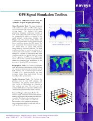
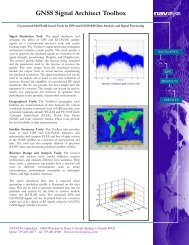
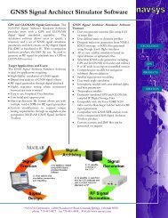
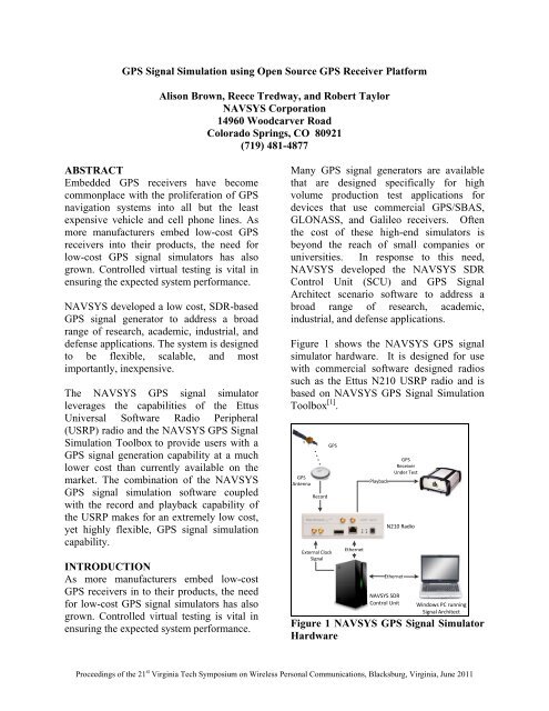
Figure 1 shows the NAVSYS <strong>GPS</strong> signal<br />
simulator hardware. It is designed for use<br />
with commercial software designed radios<br />
such as the Ettus N210 USRP radio and is<br />
based on NAVSYS <strong>GPS</strong> <strong>Signal</strong> <strong>Simulation</strong><br />
Toolbox [1] .<br />
<strong>GPS</strong><br />
Antenna<br />
Record<br />
External Clock<br />
<strong>Signal</strong><br />
<strong>GPS</strong><br />
Ethernet<br />
<strong>GPS</strong><br />
<strong>Receiver</strong><br />
Under Test<br />
Playback<br />
N210 Radio<br />
Ethernet<br />
NAVSYS SDR<br />
Control Unit<br />
Windows PC running<br />
<strong>Signal</strong> Architect<br />
Figure 1 NAVSYS <strong>GPS</strong> <strong>Signal</strong> Simulator<br />
Hardware<br />
Proceedings of the 21 st Virginia Tech Symposium on Wireless Personal Communications, Blacksburg, Virginia, June 2011
In the configuration shown in Figure 1, the<br />
NAVSYS SDR Control Unit (SCU) is used<br />
to control the Ettus radio for record and<br />
playback operation. The SDR Control Unit<br />
also includes a 10 MHz frequency standard<br />
that is compatible with the USRP radio<br />
reference clock input. The NAVSYS <strong>GPS</strong><br />
<strong>Signal</strong> Architect software can produce<br />
custom <strong>GPS</strong> scenario data files which can<br />
use the low-cost USRP to produce a <strong>GPS</strong><br />
signal at RF.<br />
Table 1 NAVSYS <strong>Signal</strong> Simulator<br />
System Specifications<br />
NAVSYS <strong>Signal</strong> Architect SW<br />
OS<br />
Windows XP/Win7<br />
Multi-Core Minimum Core i5<br />
Support<br />
Supported <strong>GPS</strong><br />
<strong>Signal</strong>s<br />
<strong>GPS</strong> L1 (1575.42 MHz) C/A<br />
and P<br />
Future System<br />
Options<br />
GNSS, multi-frequency<br />
(<strong>GPS</strong>/GLONASS 1 )<br />
NAVSYS SDR Control Unit (NSCU)<br />
RF In/Out SMA - Input/Output<br />
antenna for RF signal<br />
record/replay<br />
PC<br />
Interface: Gigabit Ethernet<br />
(GbE)<br />
OS: Windows XP/Win7<br />
RF Record/Replay Channel 1 Center<br />
Frequency: 1575.42 MHz<br />
Sample Frequency:<br />
2-20MHz<br />
Sampling: 1 or 2-bit I/Q<br />
Channel bandwidth set by<br />
RF pre-filter to<br />
match Nyquist BW (sample<br />
rate)<br />
Future System Multi-RF channel<br />
Options L1+L2+L5<br />
+GLONASS*<br />
*Notes: Expected to be released Fall 2011.<br />
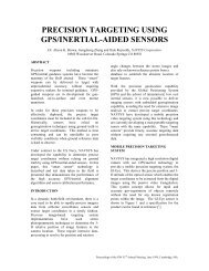
This paper provides a review of how the<br />
NAVSYS <strong>Signal</strong> Simulator uses the USRP<br />
family of radios as low cost RF record and<br />
playback devices <strong>using</strong> the <strong>Signal</strong> Architect<br />
files. In addition, the hardware design and<br />
supported signals are described and test<br />
results are presented showing the USRP<br />
providing simulated <strong>GPS</strong> signals to<br />
conventional <strong>GPS</strong> user equipment.<br />
ETTUS RADIO HARDWARE<br />
The ETTUS USRP radio family provides a<br />
low cost development platform for software<br />
defined radios. The USRP can also be used<br />
to record and play back the <strong>GPS</strong> signal in a<br />
static or mobile environment. The system<br />
operator can then reproduce the signal on<br />
the bench either from a simulated profile or<br />
from a previously recorded test<br />
environment. An advantage of the Ettus<br />
radio is that it supports a wideband<br />
transceiver front-end that can accommodate<br />
the full 20 MHz of the <strong>GPS</strong> signal band and<br />
can be tuned to operate at any of the <strong>GPS</strong><br />
signal frequencies (L1:1575.42 MHz,<br />
L2:1227.60 MHz or L5: 1176.45 MHz).<br />
This allows record and playback of both the<br />
civil and military <strong>GPS</strong> codes.<br />
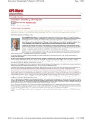
Figure 2 USRP N210 Radio<br />
While the <strong>GPS</strong> <strong>Signal</strong> Architect tools can be<br />
easily adapted for use with any commercial<br />
SDR, Ettus was chosen due to their<br />
reasonable price, quality construction, and<br />
extensive support by the GNU Radio<br />
project [2] . Of the Ettus radios, the N210 was<br />
chosen because it has the highest sample<br />
rate, greatest flexibility, and largest capacity<br />
for modification.<br />
The USRP provides an interface between<br />
high speed analog to digital converters, high<br />
speed digital to analog converters and an<br />
Ethernet interface. Daughterboards available<br />
2
for the USRP provide an interface from the<br />
baseband signals present at the data<br />
converters to the <strong>GPS</strong> frequency bands.<br />
For this project an ETTUS WBX [3]<br />
transceiver daughtercard was installed in the<br />
USRP radio. The tunable range of the WBX<br />
(50 MHz to 2.2 GHz) covers all the current<br />
GNSS frequencies. An RF pre-filter is used<br />
to band-limit the GNSS signals to the<br />
sample rate selected for use in the SCU to<br />
avoid spectral folding from the N210 40<br />
MHz channel bandwidth. For example, a 2<br />
MHz filter centered at L1 is optimal based<br />
on the Nyquist sampling frequency of 2<br />
MHz I/Q. If sampling at 20 MHz, then a 20<br />
MHz pre-filter should be used.<br />
NAVSYS SDR CONTROL UNIT (SCU)<br />
The NAVSYS SDR Control Unit includes a<br />
Linux SBC with software developed to run<br />
under the GNU Radio Companion and<br />
control the GNU SDR for RF record and<br />
playback under control of the <strong>GPS</strong> <strong>Signal</strong><br />
Architect software through an Ethernet<br />
connection to a standard PC. This enables<br />
the user to tap into the excellent USRP<br />
community support for their project and<br />
benefit from the close relationship between<br />
the GNU Radio project and Ettus Research.<br />
The Ethernet connection is also used to<br />
download and upload recorded or simulated<br />
signal files from the <strong>Signal</strong> Architect signal<br />
simulation software.<br />
SIGNAL ARCHITECT SIGNAL<br />
SIMULATION SOFTWARE<br />
The NAVSYS <strong>GPS</strong> <strong>Signal</strong> Architect<br />
hardware and software provides users with a<br />
MATLAB-based <strong>GPS</strong> signal generation<br />
capability. If the NAVSYS MATLAB <strong>GPS</strong><br />
Toolbox [1] is purchased, the <strong>Signal</strong> Architect<br />
<strong>GPS</strong> simulation can be run under the<br />
MATLAB environment. For the non-<br />
MATLAB user, the <strong>Signal</strong> Architect<br />
software is bundled as a stand-alone<br />
executable.<br />
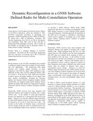
Figure 3 <strong>Signal</strong> Architect <strong>Simulation</strong><br />
Flow<br />
Using a simple, intuitive GUI, the user<br />
specifies a trajectory and a complete set of<br />
simulation parameters to create an IQ data<br />
file. The <strong>Signal</strong> Architect software also<br />
ships with preloaded scenario files that the<br />
user can run right out of the box into the<br />
NAVSYS SDR Control Unit <strong>using</strong> the Ettus<br />
radio. The <strong>Signal</strong> Architect software<br />
supports computers with multi-core<br />
processors and will automatically configure<br />
to run on all available processors. The<br />
<strong>Signal</strong> Architect software will generate<br />
either static or dynamic simulation profiles.<br />
The <strong>Signal</strong> Architect GUI allows the<br />
operator to easily modify a wide range of<br />
scenario variables from the pre-set defaults.<br />
Complete scenarios are easily shared<br />
between NAVSYS <strong>Signal</strong> <strong>Simulation</strong><br />
systems, supporting collaborative testing<br />
between similar projects and reducing the<br />
amount of time spent developing test tools.<br />
The signal data file can then be used for<br />
subsequent analysis within MATLAB <strong>using</strong><br />
the MATLAB <strong>GPS</strong> Toolbox or can be<br />
provided to the SDR Control Unit and Ettus<br />
radio to create a <strong>GPS</strong> signal suitable for<br />
playback into a <strong>GPS</strong> receiver. If the<br />
MATLAB <strong>GPS</strong> Toolbox is purchased, the<br />
user has complete flexibility to manipulate<br />
the signal at various stages of generation or<br />
post-generation to simulate <strong>GPS</strong> anomalies.<br />
Without the Toolbox, the user is restricted to<br />
3
<strong>using</strong> only the standard error modeling<br />
provided by the compiled <strong>Signal</strong> Architect<br />
code.<br />
Figure 4 <strong>Signal</strong> Architect GUI<br />
SIMULATION TEST RESULTS<br />
To demonstrate the high fidelity of the<br />
NAVSYS <strong>Signal</strong> Simulator signal record<br />
and playback capability, a series of a<br />
stationary <strong>GPS</strong> simulations were ran. In<br />
these tests the N210 radio was used to<br />
record and playback <strong>GPS</strong> C/A signals at the<br />
L1 band (1575.42 MHz). The NAVSYS<br />
SCU and Ettus N210 radio was connected to<br />
a rooftop mounted <strong>GPS</strong> L1 antenna. The<br />
<strong>GPS</strong> signal was split between the NovAtel<br />
<strong>GPS</strong> receiver and the N210 radio to allow<br />
the operator to monitor the <strong>GPS</strong> receiver<br />
while the N210 was recording the <strong>GPS</strong><br />
signal.<br />
In record mode, the I/Q data is written from<br />
the N210 radio to a file on the NAVSYS<br />
SDR Control Unit. In playback mode, the<br />
data is read from the file by the N210 radio<br />
to generate the RF signal. The RF signals<br />
are output to the <strong>GPS</strong> receive through an<br />
external variable attenuator. The attenuator<br />
allows the operator to adjust the signal<br />
power into the <strong>GPS</strong> receiver as different<br />
lengths of antenna cable are added or as the<br />
signal is split to other <strong>GPS</strong> receivers.<br />
To demonstrate the NAVSYS <strong>GPS</strong> <strong>Signal</strong><br />
Simulator performance, representative data<br />
was collected in a series of two laboratory<br />
tests. The first test demonstrates the system<br />
performance as a record and playback <strong>GPS</strong><br />
signal simulator. The second test results<br />
demonstrate the system performance when<br />
<strong>using</strong> the NAVSYS <strong>Signal</strong> Architect<br />
software to generate custom <strong>GPS</strong> scenario<br />
files for playback into the <strong>GPS</strong> receiver.<br />
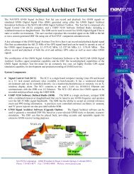
In the first test the NAVSYS EGS-100 <strong>GPS</strong><br />
Simulator hardware was configured as<br />
shown in Figure 5. The NovAtel <strong>GPS</strong><br />
receiver and Ettus N210 radio were<br />
connected to a NovAtel <strong>GPS</strong>-702GG<br />
antenna. The antenna was located at a<br />
known location with a clear view of the <strong>GPS</strong><br />
constellation. The signal from the <strong>GPS</strong><br />
antenna was split between the <strong>GPS</strong> receiver<br />
and the Ettus N210 radio so that the data<br />
could be logged by the NovAtel receiver<br />
software at the same time as it was being<br />
recorded by the NAVSYS SDR Control<br />
Unit.<br />
<strong>GPS</strong><br />
Antenna<br />
10 MHz<br />
Precision<br />
Oscillator<br />
Antenna Splitter<br />
RF Filter<br />
Ethernet<br />
N210 Radio<br />
Ethernet<br />
NAVSYS SDR<br />
Control Unit<br />
<strong>GPS</strong><br />
<strong>Receiver</strong><br />
Attenuator<br />
<strong>GPS</strong> Control<br />
Software<br />
Windows PC running<br />
<strong>Signal</strong> Architect<br />
Figure 5 NAVSYS EGS-100 <strong>GPS</strong> <strong>Signal</strong><br />
Simulator Record and Playback <strong>GPS</strong><br />
<strong>Simulation</strong><br />
4
The simulated satellite constellation is<br />
shown below in Figure 6.<br />
SNo (dB-Hz)<br />
100<br />
50<br />
SNo<br />
04/18/2011<br />
PRN 20<br />
0<br />
0 100 200 300 400 500 600 700 800<br />
SNo (dB-Hz)<br />
100<br />
50<br />
PRN 23<br />
Live Sky<br />
Record and Playback<br />
0<br />
0 100 200 300 400 500 600 700 800<br />
SNo (dB-Hz)<br />
50<br />
PRN 24<br />
0<br />
0 100 200 300 400 500 600 700 800<br />
Figure 6 Simulated Satellite Constellation<br />
The 2-D position error from the simulated<br />
signal is shown below in Figure 7.<br />
Figure 7 North-East (2-D) Position Error<br />
(m)<br />
The following series of plots show the signal<br />
to noise measurements from the <strong>GPS</strong><br />
receiver for both the live sky data and for<br />
the recorded signal when played into the<br />
<strong>GPS</strong> receiver by the EGS-100 for three of<br />
the <strong>GPS</strong> receiver channels. The S/No data<br />
collected from the <strong>GPS</strong> antenna is shown in<br />
blue, the S/No from the Ettus N210 radio is<br />
shown in green.<br />
Figure 8 SNo - Record and Playback vs.<br />
Live Sky Collection<br />
As shown, the signal to noise (SNo) was 1-2<br />
dB lower in playback mode when compared<br />
to the data collected from the <strong>GPS</strong> antenna.<br />
The signal loss is due to the 1-bit sampling<br />
of the incoming <strong>GPS</strong> signal by the <strong>Signal</strong><br />
Architect software. One-bit and 2-bit<br />
quantization are used in many commercial<br />
<strong>GPS</strong> receivers. The rule of thumb states that<br />
1-bit quantization degrades the signal-tonoise<br />
ratio by 1.96 dB and 2-bit quantization<br />
degrades the signal-to-noise by 0.55 dB 4 .<br />
These results show that 1-bit I/Q sampling is<br />
sufficient for reproducing <strong>GPS</strong> L1 C/A code<br />
signals with the Ettus N210 radio.<br />
In the second test the NAVSYS <strong>Signal</strong><br />
Architect software was used to generate a 10<br />
minute static <strong>GPS</strong> C/A L1 scenario file. The<br />
NAVSYS SDR Control Unit used the Ettus<br />
N210 radio to generate the <strong>GPS</strong> signal.<br />
Shown below in Figure 9 are the number of<br />
satellites the <strong>GPS</strong> receiver was able to track.<br />
When <strong>using</strong> the NAVSYS <strong>GPS</strong> <strong>Signal</strong><br />
simulator system to playback the <strong>Signal</strong><br />
Architect scenario file the <strong>GPS</strong> receiver was<br />
able to track all the simulated satellites in<br />
the scenario file. The time necessary for the<br />
5
<strong>GPS</strong> receiver to acquire and track the<br />
satellites is consistent with the performance<br />
you would expect from the <strong>GPS</strong> receiver<br />
when connected to an external antenna.<br />
Number of Satellites Tracked<br />
10<br />
8<br />
6<br />
4<br />
2<br />
Number of Satellites Tracked<br />
04/18/2011<br />
(DSF File Playback)<br />
DSF File Playback<br />
0<br />
0 100 200 300 400 500<br />
<strong>Simulation</strong> Seconds<br />
Figure 9 Number of Satellites Tracked,<br />
(DSF File Playback Mode)<br />
The following plot shows the signal to noise<br />
measurements from the <strong>GPS</strong> receiver for<br />
three of the receiver channels. The scenario<br />
file SNo data is shown in blue. There were<br />
nine satellites in this static scenario file. The<br />
S/No for all the satellites are stable for the<br />
duration of the scenario playback.<br />
SNo (dB-Hz)<br />
SNo (dB-Hz)<br />
SNo (dB-Hz)<br />
SNo<br />
04/18/2011<br />
PRN 3<br />
55<br />
50<br />
DSF Playback<br />
45<br />
0 100 200 300 400 500<br />
55<br />
50<br />
PRN 6<br />
45<br />
0 100 200 300 400 500<br />
55<br />
50<br />
PRN 7<br />
45<br />
0 100 200 300 400 500<br />
ideal low cost <strong>GPS</strong> signal simulation tool<br />
with the capability of simulating or<br />
recording the complete <strong>GPS</strong> signal spectrum<br />
including both the civil and the military<br />
codes for playback through the Ettus SDR<br />
The initial release of the <strong>GPS</strong> <strong>Signal</strong><br />
Architect and SCU supports L1 operation<br />
and C/A and P-code signal simulation or<br />
C/A and P(Y) code record and playback.<br />
Our team of <strong>GPS</strong> and RF experts are<br />
continually developing and updating the<br />
system in order to provide additional<br />
functionality. Future releases of our <strong>Signal</strong><br />
Simulator will include support for multifrequency<br />
SDR hardware and the capability<br />
to simulate other civil and military <strong>GPS</strong><br />
signals and also other GNSS satellite<br />
systems.<br />
ACKNOWLEDGMENTS<br />
The authors would like to acknowledge the<br />
support of Ettus Research LLC in the<br />
development of this technology.<br />
REFERENCES<br />
[1] www.navsys.com/Products/toolbox.htm<br />
[2] http://gnuradio.org<br />
[3] TX and RX Daughterboards for the<br />
USRP Software Radio System.<br />
http://www.ettus.com/downloads/ettus_daug<br />
hterboards.pdf<br />
[4] Van Dierendonck, A.J. (1996), Global<br />
Positioning System: Theory and<br />
Applications, Volume I, Chapter 8: <strong>GPS</strong><br />
<strong>Receiver</strong>s, AJ Systems, Los Altos, CA<br />
94024.<br />
Figure 10 SNo, DSF Playback Mode<br />
CONCLUSION<br />
The combination of the NAVSYS <strong>GPS</strong><br />
<strong>Signal</strong> Architect software, SDR Control<br />
Unit, and Ettus radio has proven to be an<br />
6