AN QP and ARM7/9 - Quantum Leaps
AN QP and ARM7/9 - Quantum Leaps
AN QP and ARM7/9 - Quantum Leaps

Create successful ePaper yourself
Turn your PDF publications into a flip-book with our unique Google optimized e-Paper software.
<strong>QP</strong> state machine frameworks for <strong>ARM7</strong>/ARM9<br />
Application Note<br />
<strong>QP</strong> <strong>and</strong> <strong>ARM7</strong>/9<br />
Document Revision M<br />
April 2009<br />
Copyright © <strong>Quantum</strong> <strong>Leaps</strong>, LLC<br />
www.quantum-leaps.com<br />
www.state-machine.com
Table of Contents<br />
1 Introduction........................................................................................................................................1<br />
1.1 About <strong>QP</strong>..........................................................................................................................................2<br />
1.2 About the ARM Port.............................................................................................................................2<br />
1.3 Licensing <strong>QP</strong> .......................................................................................................................................3<br />
2 Directories <strong>and</strong> Files .........................................................................................................................4<br />
2.1 Building the <strong>QP</strong> Libraries.....................................................................................................................5<br />
2.2 Building the Examples .........................................................................................................................6<br />
3 The Vanilla Port..................................................................................................................................7<br />
3.1 Compiler Options Used........................................................................................................................7<br />
3.2 The QF Port Header File .....................................................................................................................7<br />
3.2.1 The QF Critical Section................................................................................................................7<br />
3.2.2 Discussion of the QF Critical Section ........................................................................................10<br />
3.3 H<strong>and</strong>ling Interrupts ............................................................................................................................11<br />
3.3.1 The IRQ “Wrapper” Function in Assembly.................................................................................12<br />
3.3.2 The FIQ “Wrapper” Function in Assembly .................................................................................15<br />
3.3.3 Other ARM Exception “Wrapper” Functions in Assembly .........................................................17<br />
3.3.4 Defining The BSP_irq() C-level IRQ H<strong>and</strong>ler ............................................................................19<br />
3.3.5 The C-level ISRs........................................................................................................................20<br />
3.3.6 Defining The BSP_fiq() C-level IRQ H<strong>and</strong>ler.............................................................................20<br />
3.3.7 Initializing the Vector Table <strong>and</strong> the Vectored Interrupt Controller............................................21<br />
3.4 Idle Loop Customization in the “Vanilla” Port ....................................................................................22<br />
4 The QK Port......................................................................................................................................23<br />
4.1 Compiler <strong>and</strong> Linker Options Used....................................................................................................23<br />
4.2 The QK Port Header File ...................................................................................................................23<br />
4.2.1 The QK Critical Section .............................................................................................................23<br />
4.3 H<strong>and</strong>ling Interrupts ............................................................................................................................23<br />
4.3.1 The IRQ “Wrapper” Function for QK..........................................................................................24<br />
4.3.2 The FIQ “Wrapper” Function for QK ..........................................................................................26<br />
4.4 Idle Loop Customization in the QK Port ............................................................................................28<br />
5 Controlling Placement of the Code in Memory <strong>and</strong> ARM/THUMB Compilation........................29<br />
6 References .......................................................................................................................................30<br />
7 Contact Information.........................................................................................................................31<br />
Copyright © <strong>Quantum</strong> <strong>Leaps</strong>, LLC. All Rights Reserved.<br />
i
1 Introduction<br />
This Application Note describes how to use the <strong>QP</strong>/C <strong>and</strong> <strong>QP</strong>/C++ state machine frameworks version<br />
4 or higher with the <strong>ARM7</strong> or ARM9 processors. This document describes the following two main<br />
implementation options:<br />
1. The cooperative “Vanilla” kernel available in the QF real-time framework; <strong>and</strong><br />
2. The preemptive run-to-completion QK kernel.<br />
To focus the discussion, this Application Note uses the IAR Embedded Workbench ® for ARM (EWARM<br />
version 5.30 KickStart edition, which is available as a free download from the IAR website www.iar.com).<br />
However, most of the code described here is generic ARM/THUMB <strong>and</strong> should be easily adapted to any<br />
ARM development toolset, such as the RealView ® , Keil, Green Hills, or GNU.<br />
This Application Note does not contain any executable examples, which are provided in the <strong>QP</strong><br />
Development Kits (QDKs) for specific <strong>ARM7</strong>/ARM9 boards. The QDKs for ARM are available as<br />
separate downloads from www.state-machine/arm.<br />
NOTE: Even though this Application Note is based on the IAR toolset for ARM, the provided explanations are<br />
applicable to most toolsets supporting <strong>ARM7</strong>/ARM9 processors.<br />
NOTE: This Application Note pertains both to C <strong>and</strong> C++ versions of the <strong>QP</strong> state machine frameworks. Most of<br />
the code listings in this document refer to the <strong>QP</strong>/C version. Occasionally the C code is followed by the equivalent<br />
C++ implementation to show the C++ differences whenever such differences become important.<br />
Copyright © <strong>Quantum</strong> <strong>Leaps</strong>, LLC. All Rights Reserved.<br />
1 of 31
Application Note<br />
<strong>QP</strong> <strong>and</strong> <strong>ARM7</strong>/9<br />
www.state-machine.com/arm<br />
1.1 About <strong>QP</strong><br />
<strong>QP</strong> is a family of very lightweight, open source, state machine-based<br />
frameworks for developing event-driven applications. <strong>QP</strong> enables building<br />
well-structured embedded applications as a set of concurrently executing<br />
hierarchical state machines (UML statecharts) directly in C or C++ without<br />
big tools. <strong>QP</strong> is described in great detail in the book “Practical UML<br />
Statecharts in C/C++, Second Edition: Event-Driven Programming for<br />
Embedded Systems” [PSiCC2] (Newnes, 2008).<br />
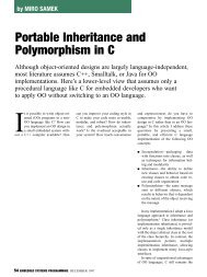
As shown in Figure 1, <strong>QP</strong> consists of a universal UML-compliant event<br />
processor (QEP), a portable real-time framework (QF), a tiny run-tocompletion<br />
kernel (QK), <strong>and</strong> software tracing instrumentation (QS). Current<br />
versions of <strong>QP</strong> include: <strong>QP</strong>/C <strong>and</strong> <strong>QP</strong>/C++, which require about 4KB<br />
of code <strong>and</strong> a few hundred bytes of RAM, <strong>and</strong> the ultra-lightweight <strong>QP</strong>nano,<br />
which requires only 1-2KB of code <strong>and</strong> just several bytes of RAM.<br />
The <strong>QP</strong>-lwIP integration described in this Application Note pertains to<br />
<strong>QP</strong>/C <strong>and</strong> <strong>QP</strong>/C++.<br />
Figure 1 <strong>QP</strong> components <strong>and</strong> their relationship with the target hardware, board support package<br />
(BSP), <strong>and</strong> the application<br />
<strong>QP</strong> can work with or without a traditional RTOS or OS. In the simplest configuration, <strong>QP</strong> can completely<br />
replace a traditional RTOS. <strong>QP</strong> includes a simple non-preemptive scheduler <strong>and</strong> a fully preemptive<br />
kernel (QK). QK is smaller <strong>and</strong> faster than most traditional preemptive kernels or RTOS, yet offers fully<br />
deterministic, preemptive execution of embedded applications. <strong>QP</strong> can manage up to 63 concurrently<br />
executing tasks structured as state machines (called active objects in UML).<br />
<strong>QP</strong>/C <strong>and</strong> <strong>QP</strong>/C++ can also work with a traditional OS/RTOS to take advantage of existing device drivers,<br />
communication stacks, <strong>and</strong> other middleware. <strong>QP</strong> has been ported to Linux/BSD, Windows, VxWorks,<br />
ThreadX, uC/OS-II, FreeRTOS.org, <strong>and</strong> other popular OS/RTOS.<br />
1.2 About the ARM Port<br />
The ARM core is a quite complicated processor in that it supports two operating states: ARM state, which<br />
executes 32-bit, word-aligned ARM instructions, <strong>and</strong> THUMB state, which operates with 16-bit, halfwordaligned<br />
THUMB instructions. On top of this, the CPU has several operating modes, such as USER,<br />
SYSTEM, SUPERVISOR, ABORT, UNDEFINED, IRQ, <strong>and</strong> FIQ. Each of these operating modes differs in<br />
visibility of registers (register banking) <strong>and</strong> sometimes privileges to execute instructions.<br />
Copyright © <strong>Quantum</strong> <strong>Leaps</strong>, LLC. All Rights Reserved.<br />
2 of 31
Application Note<br />
<strong>QP</strong> <strong>and</strong> <strong>ARM7</strong>/9<br />
www.state-machine.com/arm<br />
All these options mean that a designer must make several choices about the use of the ARM processor.<br />
This Application Note makes the following choices <strong>and</strong> assumptions:<br />
1. The ARM processor executes in both ARM <strong>and</strong> THUMB states, meaning that some parts of the code<br />
are compiled to ARM <strong>and</strong> others to THUMB instruction sets, <strong>and</strong> calls between ARM <strong>and</strong> THUMB<br />
functions are allowed. Such approach is supported by the “interwork” option of the ARM compilers<br />
<strong>and</strong> linkers. This choice is optimal for most ARM-based microcontrollers, where large parts of the<br />
code execute from slower Flash ROM that in many cases is only 16-bit wide. The higher code density<br />
of the THUMB instruction set in such cases improves performance compared to ARM, even though<br />
THUMB is a less powerful instruction set.<br />
2. The ARM processor operates in the SYSTEM mode (CPSR[0:4] = 0x1F) while processing task-level<br />
code, <strong>and</strong> briefly switches to the IRQ mode (CPSR[0:4] = 0x12) or FIQ mode (CPSR[0:4] = 0x11)<br />
to process IRQ or FIQ interrupts, respectively. The System mode is used for its ability to execute the<br />
MSR/MRS instructions necessary to quickly lock <strong>and</strong> unlock interrupts. NOTE: The SYSTEM mode is<br />
the default mode assumed by the IAR compiler for execution of applications.<br />
3. The ARM processor uses only single stack (the USER/SYSTEM stack) for all tasks, interrupts, <strong>and</strong><br />
exceptions. The private (banked) stack pointers in SUPERVISOR, ABORT, UNDEFINED, IRQ, <strong>and</strong><br />
FIQ modes are used only as working registers, but not to point to the private stacks. This means that<br />
you don’t need to allocate any RAM for the SUPERVISOR, ABORT, UNDEFINED, IRQ, or the FIQ<br />
stacks <strong>and</strong> you don’t need to initialize these stack pointers. The only stack you need to allocate <strong>and</strong><br />
initialize is the USER/SYSTEM stack.<br />
4. The application can use both IRQ <strong>and</strong> FIQ modes for processing of interrupts. The FIQ can preempt<br />
the IRQ. The interrupt locking policy includes locking simultaneously both IRQ <strong>and</strong> FIQ.<br />
1.3<br />
Licensing <strong>QP</strong><br />
The Generally Available (GA) distributions of the <strong>QP</strong> state machine frameworks available for<br />
download from the www.state-machine.com/downloads website is offered with the following two licensing<br />
options:<br />
• The GNU General Public License version 2 (GPL) as published by the Free<br />
Software Foundation <strong>and</strong> appearing in the file GPL.TXT included in the<br />
packaging of every <strong>Quantum</strong> <strong>Leaps</strong> software distribution. The GPL open<br />
source license allows you to use the software at no charge under the<br />
condition that if you redistribute the original software or applications derived<br />
from it, the complete source code for your application must be also available<br />
under the conditions of the GPL (GPL Section 2[b]).<br />
• One of several <strong>Quantum</strong> <strong>Leaps</strong> commercial licenses, which are designed for customers who wish to<br />
retain the proprietary status of their code <strong>and</strong> therefore cannot use the GNU General Public License.<br />
The customers who license <strong>Quantum</strong> <strong>Leaps</strong> software under the commercial licenses do not use the<br />
software under the GPL <strong>and</strong> therefore are not subject to any of its terms.<br />
For more information, please visit the licensing section of our website at: www.state-<br />
machine.com/licensing.<br />
Copyright © <strong>Quantum</strong> <strong>Leaps</strong>, LLC. All Rights Reserved.<br />
3 of 31
2 Directories <strong>and</strong> Files<br />
Application Note<br />
<strong>QP</strong> <strong>and</strong> <strong>ARM7</strong>/9<br />
www.state-machine.com/arm<br />
The code for the <strong>QP</strong> port to ARM is available as part of any <strong>QP</strong> Development Kit (QDK) for ARM. The<br />
QDKs assume that the generic platform-independent <strong>QP</strong> distribution has been installed.<br />
The code of the ARM port is organized according to the Application Note: “<strong>QP</strong>_Directory_Structure”.<br />
Specifically, for this port the files are placed in the following directories:<br />
/<br />
- <strong>QP</strong>/C or <strong>QP</strong>/C++ Root Directory<br />
|<br />
+-include/<br />
- <strong>QP</strong> public include files<br />
| +-qassert.h – <strong>Quantum</strong> Assertions platform-independent public include<br />
| +-qevent.h – QEvent declaration<br />
| +-qep.h – QEP platform-independent public include<br />
| +-qf.h – QF platform-independent public include<br />
| +-qk.h – QK platform-independent public include<br />
| +-qs.h – QS platform-independent public include<br />
| +-qs_dummy.h – QS “dummy” public include<br />
| +-qequeue.h – native QF event queue include<br />
| +-qmpool.h – native QF memory pool include<br />
| +-qpset.h – native QF priority set include<br />
| +-qvanilla.h – native QF non-preemptive “vanilla” kernel include<br />
|<br />
+-ports/<br />
- <strong>QP</strong>++ ports<br />
| +-arm/ - ARM port<br />
| | +-vanilla/ - “vanilla” ports<br />
| | | +-iar/ - IAR ARM compiler<br />
| | | | +-dbg/ – Debug build<br />
| | | | | +-qep_<strong>ARM7</strong>TDMI.a – QEP library for <strong>ARM7</strong>TDMI core<br />
| | | | | +-qep_ARM966E-S.a – QEP library for ARM966E-S core<br />
| | | | | +-qf_<strong>ARM7</strong>TDMI.a – QF library for <strong>ARM7</strong>TDMI core<br />
| | | | | +-qf_ARM966E-S.a – QF library for ARM966E-S core<br />
| | | | +-rel/ – Release build<br />
| | | | | +-qep_<strong>ARM7</strong>TDMI.a – QEP library for <strong>ARM7</strong>TDMI core<br />
| | | | | +-qep_ARM966E-S.a – QEP library for ARM966E-S core<br />
| | | | | +-qf_<strong>ARM7</strong>TDMI.a – QF library for <strong>ARM7</strong>TDMI core<br />
| | | | | +-qf_ARM966E-S.a – QF library for ARM966E-S core<br />
| | | | +-spy/ – Spy build<br />
| | | | | +-qep_<strong>ARM7</strong>TDMI.a – QEP library for <strong>ARM7</strong>TDMI core<br />
| | | | | +-qep_ARM966E-S.a – QEP library for ARM966E-S core<br />
| | | | | +-qf_<strong>ARM7</strong>TDMI.a – QF library for <strong>ARM7</strong>TDMI core<br />
| | | | | +-qf_ARM966E-S.a – QF library for ARM966E-S core<br />
| | | | | +-qs_<strong>ARM7</strong>TDMI.a – QS library for <strong>ARM7</strong>TDMI core<br />
| | | | | +-qs_ARM966E-S.a – QS library for ARM966E-S core<br />
| | | | +-. . . – Other ARM core builds<br />
| | | | +-src/ – Platfom-specific source directory<br />
| | | | | +-qf_port.s – Platfom-specific source code for the port<br />
| | | | +-make_<strong>ARM7</strong>TDMI.bat – Batch script to build <strong>QP</strong> libraries for <strong>ARM7</strong>TDMI core<br />
| | | | +-make_ARM966E-S.bat – Batch script to build <strong>QP</strong> libraries for ARM966E-S core<br />
| | | | +-. . . – Batch scripts to build <strong>QP</strong> libraries for other ARM cores<br />
| | | | +-qep_port.h – QEP platform-dependent public include<br />
| | | | +-qf_port.h – QF platform-dependent public include<br />
| | | | +-qs_port.h – QS platform-dependent public include<br />
| | | | +-qp_port.h – <strong>QP</strong> platform-dependent public include<br />
| | +-qk/ - QK (<strong>Quantum</strong> Kernel) ports<br />
| | | +-iar/ - IAR ARM compiler<br />
| | | | +-dbg/ – Debug build<br />
Copyright © <strong>Quantum</strong> <strong>Leaps</strong>, LLC. All Rights Reserved.<br />
4 of 31
Application Note<br />
<strong>QP</strong> <strong>and</strong> <strong>ARM7</strong>/9<br />
www.state-machine.com/arm<br />
| | | | | +-qep_<strong>ARM7</strong>TDMI.a – QEP library for <strong>ARM7</strong>TDMI core<br />
| | | | | +-qep_ARM966E-S.a – QEP library for ARM966E-S core<br />
| | | | | +-qf_<strong>ARM7</strong>TDMI.a – QF library for <strong>ARM7</strong>TDMI core<br />
| | | | | +-qf_ARM966E-S.a – QF library for ARM966E-Score<br />
| | | | | +-qk_<strong>ARM7</strong>TDMI.a – QK library for <strong>ARM7</strong>TDMI core<br />
| | | | | +-qk_ARM966E-S.a – QK library for ARM966E-S core<br />
| | | | +-rel/ – Release build<br />
| | | | | +-qep_<strong>ARM7</strong>TDMI.a – QEP library for <strong>ARM7</strong>TDMI core<br />
| | | | | +-qep_ARM966E-S.a – QEP library for ARM966E-S core<br />
| | | | | +-qf_<strong>ARM7</strong>TDMI.a – QF library for <strong>ARM7</strong>TDMI core<br />
| | | | | +-qf_ARM966E-S.a – QF library for ARM966E-S core<br />
| | | | | +-qk_<strong>ARM7</strong>TDMI.a – QK library for <strong>ARM7</strong>TDMI core<br />
| | | | | +-qk_ARM966E-S.a – QK library for ARM966E-S core<br />
| | | | +-spy/ – Spy build<br />
| | | | | +-qep_<strong>ARM7</strong>TDMI.a – QEP library for <strong>ARM7</strong>TDMI core<br />
| | | | | +-qep_ARM966E-S.a – QEP library for ARM966E-S core<br />
| | | | | +-qf_<strong>ARM7</strong>TDMI.a – QF library for <strong>ARM7</strong>TDMI core<br />
| | | | | +-qf_ARM966E-S.a – QF library for ARM966E-S core<br />
| | | | | +-qk_<strong>ARM7</strong>TDMI.a – QK library for <strong>ARM7</strong>TDMI core<br />
| | | | | +-qk_ARM966E-S.a – QK library for ARM966E-S core<br />
| | | | | +-qs_<strong>ARM7</strong>TDMI.a – QS library for <strong>ARM7</strong>TDMI core<br />
| | | | | +-qs_ARM966E-S.a – QS library for ARM966E-S core<br />
| | | | +-. . . – Other ARM core builds<br />
| | | | +-src/ – Platfom-specific source directory<br />
| | | | | +- qk_port.s – Platfom-specific source code for the port<br />
| | | | +-make_<strong>ARM7</strong>TDMI.bat – Batch script to build <strong>QP</strong> libraries for <strong>ARM7</strong>TDMI core<br />
| | | | +-make_ARM966E-S.bat – Batch script to build <strong>QP</strong> libraries for ARM966E-S core<br />
| | | | +-. . . – Batch scripts to build <strong>QP</strong> libraries for other ARM cores<br />
| | | | +-qep_port.h – QEP platform-dependent public include<br />
| | | | +-qf_port.h – QF platform-dependent public include<br />
| | | | +-qs_port.h – QS platform-dependent public include<br />
| | | | +-qp_port.h – <strong>QP</strong> platform-dependent public include<br />
Listing 1 Selected Directories <strong>and</strong> files of the <strong>QP</strong> after installing the ARM port. Directory <strong>and</strong> File<br />
names in bold indicate the elements included in the ARM port.<br />
2.1 Building the <strong>QP</strong> Libraries<br />
All <strong>QP</strong> components are deployed as libraries that you statically link to your application. The pre-built<br />
libraries for QEP, QF, QS, <strong>and</strong> QK are provided inside the \ports\ directory (see Listing 1).This<br />
section describes steps you need to take to rebuild the libraries yourself.<br />
NOTE: To achieve commonality among different development tools, <strong>Quantum</strong> <strong>Leaps</strong> software does not use the<br />
vendor-specific IDEs, such as the IAR Embedded Workbench IDE, for building the <strong>QP</strong> libraries. Instead, <strong>QP</strong> supports<br />
comm<strong>and</strong>-line build process based on simple batch scripts.<br />
The code distribution contains the batch file make_.bat for building all the libraries located in the<br />
\ports\arm\... directory. For example, to build the debug version of all the <strong>QP</strong> libraries for the<br />
<strong>ARM7</strong>TDMI core, with the IAR ARM compiler, QK kernel, you open a console window on a Windows PC,<br />
change directory to \ports\arm\qk\iar\, <strong>and</strong> invoke the batch by typing at the comm<strong>and</strong> prompt<br />
the following comm<strong>and</strong>:<br />
make_<strong>ARM7</strong>TDMI<br />
Copyright © <strong>Quantum</strong> <strong>Leaps</strong>, LLC. All Rights Reserved.<br />
5 of 31
Application Note<br />
<strong>QP</strong> <strong>and</strong> <strong>ARM7</strong>/9<br />
www.state-machine.com/arm<br />
The build process should produce the <strong>QP</strong> libraries in the location: \ports\arm\qk\iar\dbg\. The<br />
make_.bat files assume that the ARM toolset has been installed in the directory C:\tools\IAR\-<br />
ARM_KS_5.30.<br />
NOTE: You need to adjust the symbol IAR_ARM at the top of the batch scripts if you’ve installed the IAR ARM<br />
compiler into a different directory.<br />
In order to take advantage of the QS (“spy”) instrumentation, you need to build the QS version of the <strong>QP</strong><br />
libraries. You achieve this by invoking the make_.bat utility with the “spy” target, like this:<br />
make_<strong>ARM7</strong>TDMI spy<br />
The make process should produce the <strong>QP</strong> libraries in the directory: \ports\arm\vanilla\iarspy\.<br />
You choose the build configuration by providing a target to the make_.bat utility. The default target<br />
is “dbg”. Other targets are “rel”, <strong>and</strong> “spy” respectively. The following table summarizes the targets<br />
accepted by make_.bat.<br />
Software Version<br />
Debug (default)<br />
Release<br />
Spy<br />
Build comm<strong>and</strong><br />
make_<br />
make_ rel<br />
make_ spy<br />
Table 1 Make targets for the Debug, Release, <strong>and</strong> Spy software configurations<br />
2.2 Building the Examples<br />
This generic Application Note does not provide any executable examples, which require specific ARMbased<br />
target boards. Please download the <strong>QP</strong> Development Kit (QDK) for the ARM-based board that<br />
most closely matches your project. The QDKs provide working examples how to use the generic ARM<br />
port in the specific ARM chip.<br />
Copyright © <strong>Quantum</strong> <strong>Leaps</strong>, LLC. All Rights Reserved.<br />
6 of 31
3 The Vanilla Port<br />
Application Note<br />
<strong>QP</strong> <strong>and</strong> <strong>ARM7</strong>/9<br />
www.state-machine.com/arm<br />
The “vanilla” port shows how to use <strong>QP</strong> state machine frameworks on a “bare metal” ARM-based<br />
system with the cooperative “vanilla” kernel. In the “vanilla” version of the <strong>QP</strong>, the only component<br />
requiring platform-specific porting is the QF. The other two components: QEP <strong>and</strong> QS require merely<br />
recompilation <strong>and</strong> will not be discussed here. With the vanilla port you’re not using the QK component.<br />
3.1 Compiler Options Used<br />
The most important IAR compiler options used are as follows:<br />
--interwork<br />
--cpu %ARM_CORE% --dlib_config %IAR_ARM%\ARM\INC\DLib_Config_Normal.h<br />
In particular, the –-cpu %ARM_CORE% option selects the ARM processor core, such as <strong>ARM7</strong>TDMI,<br />
ARM966E-S, <strong>and</strong> others. You choose this option implicitly by invoking the make_.bat file.<br />
The option --interwork specifies ARM/THUMB interworking code generation, which is code<br />
synthesized by the compiler <strong>and</strong> linker to perform CPU mode changes when calling ARM functions from<br />
THUMB, or THUMB functions from ARM. The option --dlib_config %IAR_ARM%\ARM\INC\-<br />
DLib_Config_Normal.h specifies the normal configuration of the C/C++ runtime library. No locale<br />
interface, C locale, no file descriptor support, no multibytes in printf <strong>and</strong> scanf, <strong>and</strong> no hex floats in<br />
strtod.<br />
The freedom of choosing the instruction set means that each individual module can be compiled either to<br />
ARM (--cpu_mode arm) or THUMB (--cpu_mode thumb) for best performance <strong>and</strong> memory usage.<br />
3.2 The QF Port Header File<br />
The QF header file for the ARM port is located in \ports\arm\vanilla\iar\qf_port.h. This file<br />
specifies the interrupt locking/unlocking policy (QF critical section) as well as the interrupt “wrapper”<br />
functions in assembly.<br />
3.2.1 The QF Critical Section<br />
This QF port uses the interrupt locking policy of saving <strong>and</strong> restoring the interrupt status described as in<br />
Section 7.3.1 of the “Practical UML Statecharts in C/C++, Second Edition” [PSiCC2]. This policy allows for<br />
nesting critical sections, where the interrupts status is preserved across the critical section in a temporary<br />
stack variable. In other words, upon the exit from a critical section the interrupts are actually unlocked in<br />
the QF_INT_UNLOCK() macro only if they were unlocked before the matching QF_INT_LOCK() macro.<br />
Conversely, interrupts will remain locked after the QF_INT_UNLOCK() macro if they were locked before the<br />
matching QF_INT_LOCK() macro.<br />
As discussed in the upcoming Section “The FIQ Wrapper Function in Assembly”, you’ll typically not<br />
enable the ARM core interrupts during the FIQ interrupt processing, so the described critical section<br />
nesting will occur.<br />
The critical section in QF is defined as follows:<br />
/* fast unconditional interrupt locking/unlocking for ARM state */<br />
(1) #define QF_INT_LOCK_32() __asm("MSR cpsr_c,#(0x1F | 0x80 | 0x40)")<br />
(2) #define QF_INT_UNLOCK_32() __asm("MSR cpsr_c,#(0x1F)")<br />
(3) #if (__CPU_MODE__ == 1) /* THUMB mode */<br />
/* QF interrupt locking/unlocking */<br />
Copyright © <strong>Quantum</strong> <strong>Leaps</strong>, LLC. All Rights Reserved.<br />
7 of 31
(4) #define QF_INT_KEY_TYPE unsigned long<br />
(5) #define QF_INT_LOCK(key_) ((key_) = QF_int_lock_SYS())<br />
(6) #define QF_INT_UNLOCK(key_) QF_int_unlock_SYS(key_)<br />
(7) QF_INT_KEY_TYPE QF_int_lock_SYS(void);<br />
(8) void QF_int_unlock_SYS(QF_INT_KEY_TYPE key);<br />
Application Note<br />
<strong>QP</strong> <strong>and</strong> <strong>ARM7</strong>/9<br />
www.state-machine.com/arm<br />
#elif (__CPU_MODE__ == 2) /* ARM mode */<br />
#define QF_INT_KEY_TYPE<br />
unsigned long<br />
(9) #define QF_INT_LOCK(key_) do { \<br />
(10) (key_) = __get_CPSR(); \<br />
(11) QF_INT_LOCK_32(); \<br />
} while (0)<br />
(12) #define QF_INT_UNLOCK(key_) __set_CPSR(key_)<br />
#else<br />
#include /* for __get_CPSR()/__set_CPSR() */<br />
#error Incorrect __CPU_MODE__. Must be ARM or THUMB.<br />
#endif<br />
Listing 2 QF critical section definition<br />
(1-2) The macros QF_INT_LOCK_32()/QF_INT_UNLOCK_32() perform a very efficient unconditional<br />
interrupt locking/unlocking using just one MSR instruction with immediate argument. As indicated by<br />
the _32 suffix, these macros can only be called in the 32-bit ARM state, because only ARM state<br />
supports the MSR instruction.<br />
NOTE: In this <strong>QP</strong> port to the ARM processors, the C-level code executes exclusively in the SYSTEM mode. The<br />
interrupt locking/unlocking functions that can be called only from the C code, might as well take advantage of the<br />
known CPU mode. Note also that the macros QF_INT_LOCK_32()/ QF_INT_UNLOCK_32() are more efficient that the<br />
IAR intrinsic functions __disable_interrupt() <strong>and</strong> __enable_interrupt(), respectively. The IAR intrinsic<br />
functions must be generic to allow interrupt locking in any CPU mode (such as USER, SYSTEM, IRQ, FIQ, UNDEF,<br />
ABORT, SWI). In contrast, the QF_INT_LOCK_32()/ QF_INT_UNLOCK_32() can be simple, because they are specific<br />
only to the SYSTEM mode.<br />
(3) Interrupt locking/unlocking cannot be accomplished in the THUMB state, because the MSR/MRS<br />
instructions necessary to manipulate the CPSR register are not available in THUMB. Therefore, the<br />
only option to accomplish interrupt locking/unlocking from THUMB is to call an ARM function, such as<br />
QF_int_lock_SYS()/ QF_int_unlock_SYS().<br />
(4) The QF_INT_KEY_TYPE is defined, which means that locking policy of “saving <strong>and</strong> restoring the<br />
interrupt status” is applied. In this method, the original ARM CPSR register is saved in the variable of<br />
the type QF_INT_KEY_TYPE.<br />
(5) The interrupt locking macro resolves to a function call that returns the original ARM CPSR register <strong>and</strong><br />
saves it in the argument key_. The function QF_int_lock_SYS() is defined in assembly.<br />
NOTE: This <strong>QP</strong>-nano port does not use intrinsic functions, such as __disable_interrupts()/<br />
__enable_interrupts(), because they are more generic <strong>and</strong> consequently less optimal than the functions<br />
QF_int_lock_SYS()/ QF_int_unlock_SYS(). The generic functions must work in all ARM modes, not just the<br />
SYSTEM mode, whereas the functions QF_int_lock_SYS()/ QF_int_unlock_SYS() can be optimized to lock <strong>and</strong><br />
unlock interrupts only in the SYSTEM mode.<br />
Copyright © <strong>Quantum</strong> <strong>Leaps</strong>, LLC. All Rights Reserved.<br />
8 of 31
Application Note<br />
<strong>QP</strong> <strong>and</strong> <strong>ARM7</strong>/9<br />
www.state-machine.com/arm<br />
(6) The interrupt unlocking macro resolves to a function call that restores the original ARM CPSR register<br />
(actually only the control-bits of it) provided in the argument key_. The function<br />
QF_int_unlock_SYS() is defined in assembly.<br />
(7-8) The prototypes of the interrupt locking/unlocking functions are declared. These functions are defined<br />
in assembly <strong>and</strong> are callable both in ARM <strong>and</strong> THUMB state.<br />
NOTE: In C++ the interrupt locking/unlocking functions must be declared extern “C” to avoid C++ name decorating,<br />
which would make it difficult to define these functions in assembly.<br />
(9) The interrupt locking macro is defined inline in the ARM state.<br />
(10) The interrupt key holds the CPSR value (actually only the control-bits of it), which is obtained by<br />
means of the intrinsic function __get_CPSR(). In the ARM state, this function exp<strong>and</strong>s to a single<br />
machine instruction MRS r,CPSR_c.<br />
(11) After saving the CPSR, the interrupts are efficiently locked with macro QF_INT_LOCK_32() described<br />
in step (2) above.<br />
(12) The interrupt unlocking macro for the ISR-level restores the CPSR from the saved interrupt key<br />
value. The intrinsic function __set_CPSR() exp<strong>and</strong>s to a single machine instruction MSR CPSR_c,r.<br />
The interrupt locking <strong>and</strong> unlocking functions are defined in the assembly file \qf\arm\vanilla\-<br />
iar\qf_port.s as follows:<br />
;-----------------------------------------------------------------------------<br />
; Interrupt locking/unlocking<br />
;-----------------------------------------------------------------------------<br />
(1) SECTION .textrw:DATA:NOROOT(2)<br />
PUBLIC QF_int_lock_SYS, QF_int_unlock_SYS<br />
(2) CODE32<br />
QF_int_lock_SYS:<br />
(3) MRS r0,cpsr ; get the original CPSR in r0 to return<br />
(4) MSR cpsr_c,#(SYS_MODE | NO_INT) ; disable both IRQ/FIQ in SYSTEM mode<br />
(5) BX lr ; return the original CPSR in r0<br />
CODE32<br />
QF_int_unlock_SYS:<br />
(6) MSR cpsr_c,r0 ; restore the original CPSR from r0<br />
(7) BX lr ; return to ARM or THUMB<br />
Listing 3 Interrupt locking <strong>and</strong> unlocking functions defined in the module qf_port.s.<br />
(1) The module is declared in the section .textrw located in the DATA area. As described in “ARM® IAR<br />
C/C++ Compiler Reference Guide” [IAR 08a], the .textrw section is used for functions executing in<br />
RAM. For almost all ARM-based MCUs, the code executing from RAM is significantly faster<br />
(sometimes as much as 3-4 times faster) than code executing from ROM due to wait states<br />
necessary to access slow, <strong>and</strong> often only 16-bit wide Flash ROM. At the cost of just several bytes of<br />
RAM you get significant performance boost for the “hot-spot” interrupt locking/unlocking code.<br />
(2) The functions are entered in 32-bit ARM state.<br />
(3) The original value of CPSR is moved to r0, which is then returned from the QF_int_lock function.<br />
Copyright © <strong>Quantum</strong> <strong>Leaps</strong>, LLC. All Rights Reserved.<br />
9 of 31
Application Note<br />
<strong>QP</strong> <strong>and</strong> <strong>ARM7</strong>/9<br />
www.state-machine.com/arm<br />
(4) The IRQ <strong>and</strong> FIQ are disabled simultaneously by means of the most efficient immediate move to the<br />
CPSR_c (control bits only). Using this efficient instruction is possible, because the mode bits are<br />
known to be SYSTEM. Also, the T-bit is known to be cleared since this code executes in the ARM<br />
state.<br />
NOTE: In this ARM port, the C-level code executes exclusively in the SYSTEM mode. The interrupt locking/unlocking<br />
functions that can be called only from the C code, might as well take advantage of the known CPU mode. Because<br />
these specific interrupt locking/unlocking functions assume the SYSTEM mode, the names of these functions have<br />
been chosen to reflect this fact (QF_int_lock_SYS(), QF_int_unlock_SYS()).<br />
(5) The return from the function occurs via the BX instruction, which causes the T-bit to be set in the<br />
CPSR_c if the return address is a THUMB label.<br />
(6) The original value of CPSR, which is passed in the argument of the QF_int_unlock_SYS function is<br />
moved to CPSR_c. At this point interrupts are re-enabled if they were enabled before the matching call<br />
to QF_int_lock_SYS, or they remain disabled, if they were disabled before the call.<br />
(7) The function .QF_int_unlock_SYS returns with the BX instruction, so the T-bit is set in the CPSR_c if<br />
the return address is a THUMB label.<br />
3.2.2 Discussion of the QF Critical Section<br />
When the IRQ line of the ARM processor is asserted, <strong>and</strong> the I bit (bit CPSR[7]) is cleared, the core ends<br />
the instruction currently in progress <strong>and</strong> then starts the IRQ sequence, which performs the following<br />
actions (“ARM Architecture Reference Manual, 2 nd Edition”, Section 2.6.6 [Seal 00]):<br />
• R14_irq = address of next instruction to be executed + 4<br />
• SPSR_irq = CPSR<br />
• CPSR[4:0] = 0b10010 (enter IRQ mode)<br />
• CPSR[7] = 1, NOTE: CPSR[6] is unchanged<br />
• PC = 0x00000018<br />
The ARM Technical Note “What happens if an interrupt occurs as it is being disabled” [ARM 05], points<br />
out two potential problems. Problem 1 is related to using a particular subroutine as an IRQ h<strong>and</strong>ler <strong>and</strong> as<br />
a regular subroutine called outside of the IRQ scope <strong>and</strong> then inspecting the SPSR_IRQ register to detect<br />
in which context the h<strong>and</strong>ler function is called. This is impossible in this QF port, because the C-level IRQ<br />
h<strong>and</strong>ler is always called in the SYSTEM mode, where the application programmer has no access to the<br />
SPSR_IRQ register. Problem 2 described in the ARM Note [ARM 05] is more applicable <strong>and</strong> relates to the<br />
situation when both IRQ <strong>and</strong> FIQ are disabled simultaneously, which is actually the case in this port (see<br />
Listing 3(4)). If the IRQ is received during the CPSR write, FIQs could be disabled for the execution time of<br />
the IRQ h<strong>and</strong>ler. One of the workarounds recommended in the ARM Note is to explicitly enable FIQ very<br />
early in the IRQ h<strong>and</strong>ler. This is exactly done in the QF_irq assembler “wrapper” discussed later in this<br />
document.<br />
For completeness, this discussion should mention the Atmel Application Note “Disabling Interrupts at<br />
Processor Level” [Atmel 98a], which describes another potential problem that might occur when the IRQ<br />
or FIQ interrupt is recognized exactly at the time that it is being disabled. While the ARM core is executing<br />
the “MSR cpsr_c,#(SYS_MODE | NO_INT)” instruction (see Listing 3(4)), the interrupts are disabled only<br />
on the next clock cycle. If, for example, an IRQ interrupt occurs exactly during the execution of this<br />
instruction, the CPSR[7] bit is set both in the CPSR <strong>and</strong> SPSR_irq (Saved Program Status Register) <strong>and</strong><br />
the IRQ is entered. The problem arises when the IRQ or FIQ h<strong>and</strong>ler would manipulate the I or F bits in<br />
the SPSR register. This QF port provides the IRQ <strong>and</strong> FIQ “wrappers” in assembly that never change any<br />
Copyright © <strong>Quantum</strong> <strong>Leaps</strong>, LLC. All Rights Reserved.<br />
10 of 31
Application Note<br />
<strong>QP</strong> <strong>and</strong> <strong>ARM7</strong>/9<br />
www.state-machine.com/arm<br />
bits in the SPSR. This approach corresponds to the Workaround 1 described in the Atmel Application Note<br />
[Atmel 98a], which is safe here because the application programmer really has no way of accessing the<br />
SPSR register.<br />
NOTE: In this ARM port, the C-level code executes exclusively in the SYSTEM mode. Therefore, the banked<br />
registers SPSR_irq or SPSR_fiq aren’t really visible or accessible to the application programmer. Also accessing<br />
these registers would necessarily require assembly programming, since no st<strong>and</strong>ard compiler functions use these<br />
registers.<br />
3.3 H<strong>and</strong>ling Interrupts<br />
This generic “vanilla” port to ARM can work with or without an interrupt controller, such as the Atmel’s<br />
Advanced Interrupt Controller (AIC), Philips’ Vectored Interrupt Controller (VIC), <strong>and</strong> others.<br />
When used with an interrupt controller, the “vanilla” port assumes no “auto-vectoring”, which is described<br />
for example in the Atmel Application Note “Interrupt Management: Auto-vectoring <strong>and</strong> Prioritization”<br />
[Atmel 98b].<br />
Side Note: Auto-vectoring occurs when the following LDR instruction is located at the address 0x18 for the IRQ (this<br />
example pertains to the Atmel’s AIC):<br />
ORG 0x18<br />
LDR pc,[pc,#-0xF20]<br />
When an IRQ occurs, the ARM core forces the PC to address 0x18 <strong>and</strong> executes the LDR pc,[pc,#-0xF20]<br />
instruction. When the instruction at address 0x18 is executed, the effective address is:<br />
0x20 – 0xF20 = 0xFFFFF100<br />
(0x20 is the value of the PC when the instruction at address 0x18 is executed due to pipelining of the ARM core).<br />
This causes the ARM core to load the PC with the value read from the AIC_IVR register located at 0xFFFFF100. The<br />
read cycle causes the AIC_IVR register to return the address of the currently active interrupt service routine. Thus,<br />
the single LDR pc,[pc,#-0xF20] instruction has the effect of directly jumping to the correct ISR, which is called<br />
auto-vectoring.<br />
Instead of “auto-vectoring”, both the “vanilla” <strong>and</strong> QK ports to ARM assume that the low-level interrupt<br />
h<strong>and</strong>lers are directly invoked upon hardware interrupt requests. The IRQ/FIQ vectors (at 0x18 <strong>and</strong> 0x1C,<br />
respectively) load the PC with the address of the “wrapper” routines written in assembly.<br />
Figure 2 Typical ARM system with an interrupt controller (external to the ARM core)<br />
Figure 2 shows a typical ARM-based system with an interrupt controller. Typically, the interrupt<br />
prioritization is performed only with respect to the IRQ line, while the FIQ line is routed directly to the ARM<br />
Copyright © <strong>Quantum</strong> <strong>Leaps</strong>, LLC. All Rights Reserved.<br />
11 of 31
Application Note<br />
<strong>QP</strong> <strong>and</strong> <strong>ARM7</strong>/9<br />
www.state-machine.com/arm<br />
core. The ARM core itself performs a 2-level interrupt prioritization between the FIQ <strong>and</strong> IRQ, whereas<br />
FIQ is higher priority than the IRQ. This second-level of prioritization is performed by the I <strong>and</strong> F bits of<br />
the CPSR register, which are also used for interrupt locking <strong>and</strong> unlocking policy.<br />
Even though “auto vectoring” is not used, vectoring to a specific interrupt h<strong>and</strong>ler can still occur, but is<br />
done later, at the C-level interrupt h<strong>and</strong>ler functions implemented typically in the Board Support Package.<br />
Examples of such BSP functions for the popular interrupt controllers are provided later in this Application<br />
Note.<br />
Figure 3 shows the interrupt processing sequence in the presence of an interrupt controller (Atmel’s AIC<br />
is assumed in this example). The ARM vector addresses 0x18 <strong>and</strong> 0x1C point to the assembler “wrapper”<br />
functions QF_irq <strong>and</strong> QF_fiq, respectively. Each of these “wrapper” functions, for example QF_irq,<br />
performs context save, switches to the SYSTEM mode, <strong>and</strong> invokes a C-level function BSP_irq (or<br />
BSP_fiq for the FIQ interrupt). BSP_irq encapsulates the particular interrupt controller, from which it<br />
explicitly obtains the interrupt vector. Because the interrupt controller is used in this case, it must be<br />
initialized with the addresses of all used interrupt service routines (ISRs), such as tickIRQ() shown in<br />
Figure 3. Please note that these ISRs are regular C-functions <strong>and</strong> not __irq type functions because the<br />
interrupt entry <strong>and</strong> exit code is already provided in the assembly “wrapper” functions QF_irq <strong>and</strong> QF_fiq.<br />
Figure 3 Interrupt processing in the “vanilla” port to ARM with the Atmel’s AIC interrupt controller<br />
reset<br />
0x00<br />
LDR pc,[pc,#0x18]<br />
0x20<br />
cstartup<br />
IRQ<br />
FIQ<br />
0x18<br />
0x1C<br />
LDR pc,[pc,#0x18]<br />
LDR pc,[pc,#0x18]<br />
0x38<br />
0x3C<br />
QF_irq<br />
QF_fiq<br />
__enable_interrupt();<br />
__disable_interrupt();<br />
AIC_IVR<br />
AIC_SVR4<br />
AIC_SPU<br />
current ISR<br />
tickIRQ<br />
spurIRQ<br />
void tickIRQ(void) {<br />
uint32_t tmp = __TC_SR;<br />
QF_tick();<br />
}<br />
3.3.1 The IRQ “Wrapper” Function in Assembly<br />
The “vanilla” QF port provides interrupt “wrapper” function QF_irq() for h<strong>and</strong>ling the IRQ-type interrupts.<br />
The function is coded entirely in assembly, <strong>and</strong> is located in the file \ports\arm\vainlla\iar\-<br />
src\qf_port.s.<br />
Copyright © <strong>Quantum</strong> <strong>Leaps</strong>, LLC. All Rights Reserved.<br />
12 of 31
Application Note<br />
<strong>QP</strong> <strong>and</strong> <strong>ARM7</strong>/9<br />
www.state-machine.com/arm<br />
Listing 4 The QF_irq assembly wrapper for the “vanilla” QF port defined in qf_port.s.<br />
;-----------------------------------------------------------------------------<br />
; IRQ assembly wrapper<br />
;-----------------------------------------------------------------------------<br />
(1) SECTION .textrw:DATA:NOROOT(2)<br />
PUBLIC QF_irq<br />
EXTERN BSP_irq<br />
(2) CODE32<br />
QF_irq:<br />
; IRQ entry {{{<br />
(3) MOV r13,r0 ; save r0 in r13_IRQ<br />
(4) SUB r0,lr,#4 ; put return address in r0_SYS<br />
(5) MOV lr,r1 ; save r1 in r14_IRQ (lr)<br />
(6) MRS r1,spsr ; put the SPSR in r1_SYS<br />
(7) MSR cpsr_c,#(SYS_MODE | NO_IRQ) ; SYSTEM, no IRQ, but FIQ enabled!<br />
(8) STMFD sp!,{r0,r1} ; save SPSR <strong>and</strong> PC on SYS stack<br />
(9) STMFD sp!,{r2-r3,r12,lr} ; save APCS-clobbered regs on SYS stack<br />
(10) MOV r0,sp ; make the sp_SYS visible to IRQ mode<br />
(11) SUB sp,sp,#(2*4) ; make room for stacking (r0_SYS, r1_SYS)<br />
(12) MSR cpsr_c,#(IRQ_MODE | NO_IRQ) ; IRQ mode, IRQ disabled<br />
(13) STMFD r0!,{r13,r14} ; finish saving the context (r0_SYS,r1_SYS)<br />
(14) MSR cpsr_c,#(SYS_MODE | NO_IRQ) ; SYSTEM mode, IRQ disabled<br />
; IRQ entry }}}<br />
; NOTE: BSP_irq might re-enable IRQ interrupts (the FIQ is enabled<br />
; already), if IRQs are prioritized by the interrupt controller.<br />
;<br />
(15) LDR r12,=BSP_irq<br />
(16) MOV lr,pc ; copy the return address to link register<br />
(17) BX r12 ; call the C IRQ-h<strong>and</strong>ler (ARM/THUMB)<br />
; IRQ exit {{{<br />
(18) MSR cpsr_c,#(SYS_MODE | NO_INT) ; make sure IRQ/FIQ are disabled<br />
(19) MOV r0,sp ; make sp_SYS visible to IRQ mode<br />
(20) ADD sp,sp,#(8*4) ; fake unstacking 8 registers from sp_SYS<br />
(21) MSR cpsr_c,#(IRQ_MODE | NO_INT) ; IRQ mode, both IRQ/FIQ disabled<br />
(22) MOV sp,r0 ; copy sp_SYS to sp_IRQ<br />
(23) LDR r0,[sp,#(7*4)] ; load the saved SPSR from the stack<br />
(24) MSR spsr_cxsf,r0 ; copy it into spsr_IRQ<br />
(25) LDMFD sp,{r0-r3,r12,lr}^ ; unstack all saved USER/SYSTEM registers<br />
(26) NOP ; can't access banked reg immediately<br />
(27) LDR lr,[sp,#(6*4)] ; load return address from the SYS stack<br />
(28) MOVS pc,lr ; return restoring CPSR from SPSR<br />
; IRQ exit }}}<br />
Copyright © <strong>Quantum</strong> <strong>Leaps</strong>, LLC. All Rights Reserved.<br />
13 of 31
Application Note<br />
<strong>QP</strong> <strong>and</strong> <strong>ARM7</strong>/9<br />
www.state-machine.com/arm<br />
(1) The IRQ wrapper QF_irq is defined in section .textrw, declared as DATA to be placed in RAM for<br />
fastest execution. Such time-critical ARM code is best executed from 32-bit wide memory with<br />
minimal number of wait states.<br />
(2) The IRQ h<strong>and</strong>ler must be written in the 32-bit instruction set (ARM), because the ARM core<br />
automatically switches to the ARM state when IRQ is recognized.<br />
(3) The IRQ stack is not used, so the banked stack pointer register r13_IRQ (sp_IRQ) is used as a<br />
scratchpad register to temporarily hold r0 from the SYSTEM context.<br />
NOTE: As part of the IRQ startup sequence, the ARM processor sets the I bit in the CPSR (CPSR[7] = 1), but<br />
leaves the F bit unchanged (typically cleared), meaning that further IRQs are disabled, but FIQs are not. This means<br />
that FIQ can be recognized while the ARM core is in the IRQ mode. This IRQ h<strong>and</strong>ler does not disable the FIQ <strong>and</strong><br />
preemption, <strong>and</strong> the provided FIQ h<strong>and</strong>ler can safely preempt this IRQ until FIQs are explicitly disabled later in the<br />
sequence.<br />
(4) Now r0 can be clobbered with the return address from the interrupt that needs to be saved to the<br />
SYSTEM stack.<br />
(5) At this point the banked lr_IRQ register can be reused to temporarily hold r1 from the SYSTEM<br />
context.<br />
(6) Now r1 can be clobbered with the value of SPSR_IRQ register (Saved Program Status Register) that<br />
needs to be saved to the SYSTEM stack.<br />
(7) Mode is changed to SYSTEM with IRQ interrupt disabled, but FIQ explicitly enabled. This mode switch<br />
is performed to get access to the SYSTEM registers.<br />
NOTE: The F bit in the CPSR is intentionally cleared at this step (meaning that the FIQ is explicitly enabled). Among<br />
others, this represents the workaround for the Problem 2 described in ARM Technical Note “What happens if an<br />
interrupt occurs as it is being disabled” [ARM 05].<br />
(8) The SPSR register <strong>and</strong> the return address from the interrupt (PC after the interrupt) are pushed on the<br />
SYSTEM stack.<br />
(9) All registers (except r0 <strong>and</strong> r1) clobbered by the AAPCS (ARM Architecture Procedure Call St<strong>and</strong>ard)<br />
[ARM 06] are pushed on the SYSTEM stack.<br />
(10) The SYSTEM stack pointer is placed in r0 to be visible in the IRQ mode.<br />
(11) The SYSTEM stack pointer is adjusted to make room for two more registers of the saved IRQ<br />
context. By adjusting the SYSTEM stack pointer, the IRQ h<strong>and</strong>ler can still keep FIQ enabled without<br />
the concern of corrupting the SYSTEM stack space reserved for the IRQ context.<br />
(12) The mode is switched back to IRQ with IRQ interrupt disabled, but FIQ still enabled. This is done to<br />
get access to the rest of the context sitting in the IRQ-banked registers.<br />
(13) The context is entirely saved by pushing the original r0 <strong>and</strong> r1 (still sitting in the banked IRQ<br />
Registers r14_IRQ <strong>and</strong> r13_IRQ, respectively) to the SYSTEM stack. At this point the saved<br />
SYSTEM stack frame contains 8 registers <strong>and</strong> looks as follows (this is exactly the ARM v7-M interrupt<br />
stack frame [ARM 06]):<br />
high memory<br />
SPSR<br />
PC (return address)<br />
LR<br />
| R12<br />
v<br />
R3<br />
Copyright © <strong>Quantum</strong> <strong>Leaps</strong>, LLC. All Rights Reserved.<br />
14 of 31
Application Note<br />
<strong>QP</strong> <strong>and</strong> <strong>ARM7</strong>/9<br />
www.state-machine.com/arm<br />
stack<br />
growth<br />
low memory<br />
R2<br />
R1<br />
R0
Application Note<br />
<strong>QP</strong> <strong>and</strong> <strong>ARM7</strong>/9<br />
www.state-machine.com/arm<br />
purpose interrupt is actually more complicated (<strong>and</strong> thus actually more expensive) than h<strong>and</strong>ling of IRQ-type<br />
interrupts that typically are prioritized in the interrupt controller.<br />
Perhaps the best use of the FIQ is as a Non-Maskable-Interrupt (NMI) for h<strong>and</strong>ling very special functions. To use FIQ<br />
as a NMI, you must modify the critical section discussed in Section 3.2.1. Specifically, you would need to set only the<br />
I bit in the CPSR (see Listing 3(4)):<br />
MSR<br />
cpsr_c,#(SYS_MODE | NO_IRQ) ; disable only IRQ in SYSTEM mode<br />
However, please note that if you use FIQ as a NMI, you cannot use FIQ to call any QF services because the critical<br />
section never masks the FIQ <strong>and</strong> consequently such NMI can corrupt critical QF data.<br />
The “vanilla” QF port provides interrupt “wrapper” function QF_fiq() for h<strong>and</strong>ling the FIQ-type interrupts.<br />
The function is coded entirely in assembly, <strong>and</strong> is located in the file \ports\arm\vainlla\iar\-<br />
src\qf_port.s.<br />
Listing 5 The QF_fiq assembly wrapper for the “vanilla” QF port defined in qf_port.s.<br />
;-----------------------------------------------------------------------------<br />
; FIQ assembly wrapper<br />
;-----------------------------------------------------------------------------<br />
SECTION .textrw:DATA:NOROOT(2)<br />
PUBLIC QF_fiq<br />
EXTERN BSP_fiq<br />
CODE32<br />
QF_fiq:<br />
; FIQ entry {{{<br />
(1) MOV r13,r0 ; save r0 in r13_FIQ<br />
SUB r0,lr,#4 ; put return address in r0_SYS<br />
MOV lr,r1 ; save r1 in r14_FIQ (lr)<br />
MRS r1,spsr ; put the SPSR in r1_SYS<br />
(2) MSR cpsr_c,#(SYS_MODE | NO_INT) ; SYSTEM mode, IRQ/FIQ disabled<br />
STMFD sp!,{r0,r1} ; save SPSR <strong>and</strong> PC on SYS stack<br />
STMFD sp!,{r2-r3,r12,lr} ; save APCS-clobbered regs on SYS stack<br />
MOV r0,sp ; make the sp_SYS visible to FIQ mode<br />
SUB sp,sp,#(2*4) ; make room for stacking (r0_SYS, r1_SYS)<br />
MSR cpsr_c,#(FIQ_MODE | NO_INT) ; FIQ mode, IRQ/FIQ disabled<br />
STMFD r0!,{r13,r14} ; finish saving the context (r0_SYS, r1_SYS)<br />
MSR cpsr_c,#(SYS_MODE | NO_INT) ; SYSTEM mode, IRQ/FIQ disabled<br />
; FIQ entry }}}<br />
; NOTE:<br />
; Because FIQ is typically NOT prioritized by the interrupt controller<br />
; BSP_fiq must not enable IRQ/FIQ to avoid priority inversions!<br />
;<br />
LDR r12,=BSP_fiq<br />
MOV lr,pc ; store the return address<br />
(3) BX r12 ; call the C FIQ-h<strong>and</strong>ler (ARM/THUMB)<br />
Copyright © <strong>Quantum</strong> <strong>Leaps</strong>, LLC. All Rights Reserved.<br />
16 of 31
Application Note<br />
<strong>QP</strong> <strong>and</strong> <strong>ARM7</strong>/9<br />
www.state-machine.com/arm<br />
; FIQ exit {{{ ; both IRQ/FIQ disabled (see NOTE above)<br />
MSR cpsr_c,#(SYS_MODE | NO_INT) ; make sure IRQ/FIQ are disabled<br />
MOV r0,sp ; make sp_SYS visible to FIQ mode<br />
ADD sp,sp,#(8*4) ; fake unstacking 8 registers from sp_SYS<br />
MSR cpsr_c,#(FIQ_MODE | NO_INT) ; FIQ mode, IRQ/FIQ disabled<br />
MOV sp,r0 ; copy sp_SYS to sp_FIQ<br />
LDR r0,[sp,#(7*4)] ; load the saved SPSR from the stack<br />
MSR spsr_cxsf,r0 ; copy it into spsr_FIQ<br />
LDMFD sp,{r0-r3,r12,lr}^ ; unstack all saved USER/SYSTEM registers<br />
NOP<br />
; can't access banked reg immediately<br />
LDR lr,[sp,#(6*4)] ; load return address from the SYS stack<br />
MOVS pc,lr ; return restoring CPSR from SPSR<br />
; FIQ exit }}}<br />
The QF_fiq() “wrapper” shown in Listing 5 is very similar to the IRQ wrapper (Listing 4), except the FIQ<br />
mode is used instead of the IRQ mode. The following comments explain only the slight, but important<br />
differences in disabling interrupts <strong>and</strong> the responsibilities of the C-level h<strong>and</strong>ler BSP_fiq() function.<br />
(1) The FIQ h<strong>and</strong>ler is always entered with both IRQ <strong>and</strong> FIQ disabled, so the FIQ mode is not visible in<br />
any other modes.<br />
(2) The mode is switched to SYSTEM to get access to the SYSTEM stack pointer. Please note that both<br />
IRQ <strong>and</strong> FIQ interrupts are kept disabled throughout the FIQ h<strong>and</strong>ler.<br />
(3) The C-function BSP_fiq() is called to perform the interrupt processing at the application-level. Please<br />
note that BSP_fiq() is now a regular C function in ARM or THUMB. Unlike the IRQ, the FIQ interrupt<br />
is often not covered by the priority controller, therefore the BSP_fiq() should NOT unlock interrupts.<br />
NOTE: The BSP_fiq() function is entered with both IRQ <strong>and</strong> FIQ interrupts disabled <strong>and</strong> it should never enable any<br />
interrupts. Typically, the FIQ line to the ARM core does not have a priority controller, even though the IRQ line<br />
typically goes through a hardware interrupt controller.<br />
In particular, the BSP_fiq() function must NEVER enable the IRQ interrupt, because this could corrupt the banked<br />
lr_IRQ register in case the FIQ nests on top of IRQ (which is always possible due to the ARM processor<br />
architecture).<br />
3.3.3 Other ARM Exception “Wrapper” Functions in Assembly<br />
The “vanilla” QF port provides also assembly “wrapper” functions for all other ARM exceptions, which are:<br />
RESET, UNDEFINED INSTRUCTION, SOFTWARE INTERRUPT, PREFETCH ABORT, DATA ABORT,<br />
<strong>and</strong> the RESERVED exception. All these exception h<strong>and</strong>lers are coded entirely in assembly, <strong>and</strong> are<br />
located in the file \ports\arm\vainlla\iar\src\qf_port.s.<br />
The policy of h<strong>and</strong>ling the ARM hardware exceptions in QF is to raise an assertion, an assumption here<br />
being that no ARM exception should occur during normal program execution. You can easily substitute<br />
this st<strong>and</strong>ard behavior for selected ARM exceptions by simply initializing the ARM vector table to your<br />
own implementations (see Listing 9(3-10)).<br />
Listing 6 ARM Exception “Wrapper” Functions in Assembly defined in qf_port.s.<br />
PUBLIC QF_reset<br />
PUBLIC QF_undef<br />
PUBLIC QF_swi<br />
PUBLIC QF_pAbort<br />
Copyright © <strong>Quantum</strong> <strong>Leaps</strong>, LLC. All Rights Reserved.<br />
17 of 31
Application Note<br />
<strong>QP</strong> <strong>and</strong> <strong>ARM7</strong>/9<br />
www.state-machine.com/arm<br />
PUBLIC QF_dAbort<br />
PUBLIC QF_reserved<br />
EXTERN Q_onAssert<br />
SECTION .text:CODE:NOROOT(2)<br />
CODE32<br />
QF_reset:<br />
LDR r0,Csting_reset<br />
B QF_except<br />
QF_undef:<br />
LDR r0,Csting_undef<br />
B QF_except<br />
QF_swi:<br />
LDR r0,Csting_swi<br />
B QF_except<br />
(1) QF_pAbort:<br />
(2) LDR r0,Csting_pAbort<br />
(3) B QF_except<br />
QF_dAbort:<br />
LDR r0,Csting_dAbort<br />
B QF_except<br />
QF_reserved:<br />
LDR r0,Csting_reserved<br />
B QF_except<br />
(4) QF_except:<br />
(5) SUB r1,lr,#4 ; set line number to the exception address<br />
(6) MSR cpsr_c,#(SYS_MODE | NO_INT) ; SYSTEM mode, IRQ/FIQ disabled<br />
(7) LDR r12,=Q_onAssert<br />
(8) MOV lr,pc ; store the return address<br />
(9) BX r12 ; call the assertion-h<strong>and</strong>ler (ARM/THUMB)<br />
; the assertion h<strong>and</strong>ler should not return, but in case it does<br />
; hang up the machine in this endless loop<br />
B .<br />
LTORG ; strings enclosed in "" are zero-terminated<br />
Csting_reset: DC8 "Reset"<br />
Csting_undef: DC8 "Undefined"<br />
Csting_swi: DC8 "Software Int"<br />
Csting_pAbort: DC8 "Prefetch Abort"<br />
Csting_dAbort: DC8 "Data Abort"<br />
Csting_reserved: DC8 "Reserved"<br />
(1) All exceptions are h<strong>and</strong>led uniformly, such as the PREFETCH ABORT exception.<br />
(2) The first argument to the Q_onAssert() callback function is prepared in r0. This argument is a<br />
pointer to the C-string with the name of the exception.<br />
(3-4) The common exception code is h<strong>and</strong>led in at the QF_except label.<br />
(5) The address of the exception is saved in r1, which is the second argument to the Q_onAssert()<br />
callback function .<br />
(6) The mode is switched to SYSTEM with both IRQ <strong>and</strong> FIQ interrupts disabled.<br />
(7-9) The Q_onAssert() callback function is called. Because the call happens via the BX instruction, the<br />
Q_onAssert() function can be in ARM or THUMB.<br />
Copyright © <strong>Quantum</strong> <strong>Leaps</strong>, LLC. All Rights Reserved.<br />
18 of 31
Application Note<br />
<strong>QP</strong> <strong>and</strong> <strong>ARM7</strong>/9<br />
www.state-machine.com/arm<br />
3.3.4 Defining The BSP_irq() C-level IRQ H<strong>and</strong>ler<br />
The QF_irq() “wrapper” assembly function calls application-specific function BSP_irq() that performs<br />
interrupt processing in C. The BSP_irq() h<strong>and</strong>ler function is a regular C-function without any adornments<br />
(no __irq !), which is typically defined in the Board Support Package for the specific ARM silicon (more<br />
exactly for the specific interrupt controller integrated with the ARM core). The function can also be<br />
programmed in ARM or THUMB, but perhaps using ARM would lend a slightly better performance (if the<br />
function runs from a 32-bit wide memory).<br />
While you can use the BSP_irq() callback function to implement directly the body of the IRQ interrupt,<br />
most likely you will use it to encapsulate the specific interrupt controller used with the ARM core.<br />
Typically, the function obtains the current vector address from the interrupt controller, calls this vector,<br />
<strong>and</strong> writes the EOI comm<strong>and</strong> to the interrupt controller (see Figure 3).<br />
The following Listing 7 shows the implementations of the BSP_irq() functions for the Atmel’s AIC <strong>and</strong><br />
Philips VIC interrupt vector controllers.<br />
Listing 7 The BSP_irq() implementations for the Atmel’s AIC (top), <strong>and</strong> the Philips’ VIC (bottom).<br />
/* BSP_irq() for the Atmel’s AIC ...........................................*/<br />
(1a) __arm __ramfunc void BSP_irq(void) {<br />
(2a) QF_INT_UNLOCK_ARM();<br />
(3a) (*(void (*)(void))__AIC_IVR)(); /* call the ISR h<strong>and</strong>ler */<br />
(4a) QF_INT_LOCK_ARM();<br />
(5a) __AIC_EOICR = 0; /* write AIC_EOICR to clear interrupt */<br />
}<br />
/* BSP_irq() for the Philips’ VIC .........................................*/<br />
(1b) __arm __ramfunc void BSP_irq(void) {<br />
(2a) QF_INT_UNLOCK_ARM();<br />
(3b) (*(void (*)(void))VICVectAddr)(); /* call the ISR h<strong>and</strong>ler */<br />
(4a) QF_INT_LOCK_ARM();<br />
(5b) VICVectAddr = 0; /* write End-Of-Interrupt to the VIC */<br />
}<br />
(1a,b) The function BSP_irq() is defined as __arm to be able to use the most efficient interrupt unlocking<br />
<strong>and</strong> locking via the QF_INT_UNLOCK_ARM()/QF_INT_LOCK_ARM() defined as inline assembly in Listing<br />
2(7-8). Also, compiling BSP_irq() in the ARM state avoids costly ARM->THUMB state switch<br />
(accomplished by a “call-veneer” synthesized by the compiler <strong>and</strong> linker). Finally, BSP_irq() is<br />
defined also as __ramfunc to execute from the RAM, which is only done for better performance. In<br />
most ARM system, the RAM is significantly faster than the ROM <strong>and</strong> also is typically 32-bit wide,<br />
while the ROM often is connected via 16-bit bus.<br />
(2a,b) The IRQ interrupts are very efficiently unlocked (both IRQ <strong>and</strong> FIQ) via the QF_INT_UNLOCK_ARM()<br />
macro so that the interrupt controller can h<strong>and</strong>le interrupt nesting <strong>and</strong> prioritization. Please note that<br />
the QF_INT_UNLOCK() macro cannot be used here, because the interrupt unlocking is unconditional.<br />
Please note that enabling IRQs is safe, because the interrupt controller provides prioritization of the<br />
IRQs before they even reach the ARM core (see Figure 2).<br />
(3a,b) The vector address is extracted from the AIC or the VIC. This address is then cast on a (void<br />
(*)(void)) function pointer, so that the C compiler can invoke the interrupt service routine (ISR).<br />
(4a,b) The interrupts are locked for the exit sequence.<br />
(5a,b) After the ISR returns, the EOI comm<strong>and</strong> is written to the AIC or VIC. The BSP_irq() function must<br />
always return with interrupts locked.<br />
Copyright © <strong>Quantum</strong> <strong>Leaps</strong>, LLC. All Rights Reserved.<br />
19 of 31
3.3.5 The C-level ISRs<br />
Application Note<br />
<strong>QP</strong> <strong>and</strong> <strong>ARM7</strong>/9<br />
www.state-machine.com/arm<br />
When an interrupt controller is used in BSP_irq(), you must initialize the interrupt controller with the<br />
addresses of the C-level ISRs <strong>and</strong> you must define these functions in C. These ISRs are normal C<br />
functions (not __irq-type functions). The ISRs can be also compiled to ARM or THUMB without<br />
restrictions. The following shows an example of the tickISR() ISR function for the Philips LPC213X<br />
ARM-based microcontroller.<br />
Listing 8 An example of the ISR_tick() interrupt function in C.<br />
(1) __arm void ISR_tick(void) {<br />
(2) T1IR = 0x1; /* clear the interrupt source */<br />
(3) QF_tick(); /* perform clock-tick processing */<br />
}<br />
(1) The C-level ISR is a regular void (void) C-function. The IRQ-type ISR is called in SYSTEM mode<br />
with interrupts unlocked at the ARM-core level.<br />
NOTE: Here, the ISR is defined as an ARM function (via the __arm extended keyword) to avoid state switch from<br />
ARM to THUMB, because BSP_irq() is also defined as an ARM function. However, using ARM mode is here just a<br />
fine-tuning option <strong>and</strong> is not necessary for correctness. You could use THUMB mode (default) as well.<br />
(2) Any level-sensitive interrupt sources must be cleared, such as the LPC2138 timer. Please note that<br />
even though the interrupts are unlocked at the ARM core level, they are still prioritized in the interrupt<br />
controller, so a level-sensitive interrupt source will not cause recursive ISR reentry.<br />
(3) The work of the interrupt is performed with interrupts enabled at the ARM core level. Please note that<br />
the interrupt controller prevents the same level of interrupt from preempting the currently serviced<br />
level, so QF_tick() will never be reentered.<br />
3.3.6 Defining The BSP_fiq() C-level IRQ H<strong>and</strong>ler<br />
The QF_fiq() “wrapper” assembly function calls application-specific function BSP_fiq() that performs<br />
interrupt processing in C. The BSP_fiq() h<strong>and</strong>ler function is a regular C-function without any adornments<br />
(no __fiq !), which is typically defined in the Board Support Package for the specific ARM silicon (more<br />
exactly for the specific interrupt controller integrated with the ARM core). The function can also be<br />
programmed in ARM or THUMB, but perhaps using ARM would lend a slightly better performance (if the<br />
function runs from a 32-bit wide memory).<br />
Typically, you will use the BSP_fiq() callback function to implement directly the body of the FIQ interrupt<br />
h<strong>and</strong>ler. The following code snippet shows the template of the BSP_fiq() h<strong>and</strong>ler that you can customize<br />
in your applications:<br />
__arm __ramfunc void BSP_fiq(void) {<br />
/* TBD: implement the FIQ h<strong>and</strong>ler directly right here */<br />
/* NOTE: Do NOT enable interrupts throughout the whole FIQ processing. */<br />
/* NOTE: Do NOT write EOI to the AIC */<br />
}<br />
NOTE: In contrast to IRQ, the FIQ line to the ARM processor core often has no priority controller, even though the<br />
ARM processor might be equipped with an interrupt controller (see Figure 2). Therefore, it’s important not to enable<br />
interrupts during h<strong>and</strong>ling of FIQ because without a priority controller this can lead to priority inversions. It’s especially<br />
important to never enable the IRQ during processing of FIQ because this can lead to corruption of the lr_IRQ register<br />
if the FIQ happens to nest on top of IRQ, which is always possible in the ARM architecture.<br />
Copyright © <strong>Quantum</strong> <strong>Leaps</strong>, LLC. All Rights Reserved.<br />
20 of 31
Application Note<br />
<strong>QP</strong> <strong>and</strong> <strong>ARM7</strong>/9<br />
www.state-machine.com/arm<br />
3.3.7 Initializing the Vector Table <strong>and</strong> the Vectored Interrupt Controller<br />
Auto-vectoring is NOT used, so the ARM vector table <strong>and</strong> the interrupt controller must be correctly<br />
initialized differently than in other QK port. The following listing shows the initialization placed in the<br />
QF_onStart() callback.<br />
Listing 9 Initialization of the ARM vector table <strong>and</strong> the interrupt controller in QF_onStart() for the<br />
Philips LPC213x.<br />
(1) __arm void QF_onStart(void) {<br />
(2) QF_INT_LOCK_ARM(); /* lock interrupts */<br />
/* hook the IRQ h<strong>and</strong>ler from the QK port */<br />
(3) *(uint32_t volatile *)0x24 = (uint32_t)&QF_undef;<br />
(4) *(uint32_t volatile *)0x28 = (uint32_t)&QF_swi;<br />
(5) *(uint32_t volatile *)0x2C = (uint32_t)&QF_pAbort;<br />
(6) *(uint32_t volatile *)0x30 = (uint32_t)&QF_dAbort;<br />
(7) *(uint32_t volatile *)0x34 = (uint32_t)&QF_reserved;<br />
(8) *(uint32_t volatile *)0x38 = (uint32_t)&QF_irq;<br />
(9) *(uint32_t volatile *)0x3C = (uint32_t)&QF_fiq;<br />
VICIntSelect = 0x0; /* assign all interrupts to the IRQ category */<br />
/* Setting up Timer1 to h<strong>and</strong>le the time tick interrupt.<br />
* Timer1 has priorty 1 (second to the highest)<br />
*/<br />
VICVectCntl1 = 0x25;<br />
(10) VICVectAddr1 = (uint32_t)&ISR_tick;<br />
VICIntEnable = (1
3.4 Idle Loop Customization in the “Vanilla” Port<br />
Application Note<br />
<strong>QP</strong> <strong>and</strong> <strong>ARM7</strong>/9<br />
www.state-machine.com/arm<br />
As described in Chapter 7 of [PSiCC2], the “vanilla” port uses the non-preemptive scheduler built into QF.<br />
If no events are available, the non-preemptive scheduler invokes the platform-specific callback function<br />
QF_onIdle(), which you can use to save CPU power, or perform any other “idle” processing (such as<br />
<strong>Quantum</strong> Spy software trace output).<br />
NOTE: The idle callback QF_onIdle() must be invoked with interrupts locked, because the idle condition can be<br />
changed by any interrupt that posts events to event queues. QF_onIdle() must internally unlock interrupts, ideally<br />
atomically with putting the CPU to the power-saving mode. If the interrupt lock key is defined (the “save <strong>and</strong> restore”<br />
interrupt locking policy), QF_onIdle() must take the interrupt lock key as parameter, to be able to unlock the<br />
interrupts internally.<br />
Because QF_onIdle() must enable interrupts internally, the signature of the function depends on the<br />
interrupt locking policy. In case of the “save <strong>and</strong> restore interrupt status” policy, which is used in this ARM<br />
port, the QF_onIdle() takes the interrupt status as a parameter, to be able to use the QF_INT_UNLOCK()<br />
macro to unlock the interrupts.<br />
The following Listing 10 shows an example implementation of QF_onIdle() for the Philips LPC2xxx CPU.<br />
Other ARM-based embedded microcontrollers (e.g., Atmel’s AT91) h<strong>and</strong>le the power-saving mode very<br />
similarly.<br />
Listing 10 QF_onIdle() callback for the Philips LPC2xxx CPU<br />
(1) void QF_onIdle(QF_INT_KEY_TYPE key) { /* NOTE: called with interrupts LOCKED */<br />
(2) PCON_bit.IDL = 1; /* go to idle mode to save power */<br />
(3) QF_INT_UNLOCK(key); /* unlock interrupts as soon as CPU clock starts */<br />
}<br />
(1) The signature of QF_onIdle() must be consistent with the interrupt locking policy. In case of the “save<br />
<strong>and</strong> restore interrupt status” policy, the function takes the interrupt lock key as the parameter.<br />
(2) Setting the PCON_bit.IDL bit stops the CPU clock on the LPC2xxx. Please note that the code stops<br />
executing at this line <strong>and</strong> that interrupts are still locked. The implementation of power saving in this<br />
microcontroller family is such that any active interrupt turns on the CPU clock, if it’s stopped.<br />
(3) Only after putting the CPU into low-power mode interrupts are unlocked (please note the use of the<br />
interrupt lock key).<br />
Copyright © <strong>Quantum</strong> <strong>Leaps</strong>, LLC. All Rights Reserved.<br />
22 of 31
4 The QK Port<br />
Application Note<br />
<strong>QP</strong> <strong>and</strong> <strong>ARM7</strong>/9<br />
www.state-machine.com/arm<br />
The QK ports show how to use <strong>QP</strong> state machine frameworks on the ARM processor with QK, which is<br />
a very lightweight, preemptive, priority-based kernel designed specifically for QF (see Chapter 10 in<br />
PSiCC2). You should consider the QK port if your application requires deterministic, real-time<br />
performance <strong>and</strong> also the application can benefit from decoupling higher-priority tasks from lower-priority<br />
tasks in the time domain. Perhaps the best way to learn about QK implementation for the ARM processor<br />
is to study Chapter 10 in PSiCC2. You might also read the article “Build Super Simple Tasker” [Samek+<br />
06], which explains the inner-workings of a single-stack preemptive kernel, like QK.<br />
One of the biggest advantages of QK is that porting QK to a new microprocessor is very easy. In fact the<br />
QK port to ARM is almost identical to the simplest “vanilla” port described in Section 3. The main<br />
difference between the two ports, which is visible at the application level, is that you use QK_irq() <strong>and</strong><br />
QK_fiq() “wrapper” functions for interrupt processing (instead of QF_irq() <strong>and</strong> QF_fiq(), respectively).<br />
The other slight difference is that you customize the idle loop processing in a different way than in the<br />
“vanilla” port. This section focuses only on the differences from the “vanilla” port.<br />
4.1 Compiler <strong>and</strong> Linker Options Used<br />
The QK port uses exactly the same compiler options as the “vanilla” <strong>QP</strong> port described in Section 3.1.<br />
4.2 The QK Port Header File<br />
The QK header file for the ARM, IAR compiler is located in \ports\arm\qk\iar\qk_port.h. This<br />
file specifies the interrupt enabling/disabling policy (QK critical section) as well as the interrupt <strong>and</strong><br />
exception h<strong>and</strong>ling “wrapper” functions defined in assembly.<br />
4.2.1 The QK Critical Section<br />
The QK port uses the same critical section as the “Vanilla” port described in Section 3.2.1. The critical<br />
section is defined in the header file \ports\arm\qk\iar\qf_port.h.<br />
4.3 H<strong>and</strong>ling Interrupts<br />
This generic QK port to ARM can work with or without an interrupt controller, such as the Atmel’s<br />
Advanced Interrupt Controller (AIC), Philips’ Vectored Interrupt Controller (VIC), <strong>and</strong> others.<br />
When used with an interrupt controller, the QK port assumes no “auto-vectoring”, which is described for<br />
example in the Atmel Application Note “Interrupt Management: Auto-vectoring <strong>and</strong> Prioritization” [Atmel<br />
98b] (see also Section 3.3).<br />
Figure 4 shows the interrupt processing sequence in the presence of an interrupt controller (Atmel’s AIC<br />
is assumed in this example). The ARM vector addresses 0x18 <strong>and</strong> 0x1C point to the assembler “wrapper”<br />
functions QK_irq <strong>and</strong> QK_fiq, respectively. Each of these “wrapper” functions, for example QK_irq,<br />
performs context save, switches to the SYSTEM mode, <strong>and</strong> invokes a C-level function BSP_irq (or<br />
BSP_fiq for the FIQ interrupt). BSP_irq encapsulates the particular interrupt controller, from which it<br />
explicitly obtains the interrupt vector. Because the interrupt controller is used in this case, it must be<br />
initialized with the addresses of all used interrupt service routines (ISRs), such as tickIRQ() shown in<br />
Figure 4. Please note that these ISRs are regular C-functions <strong>and</strong> not __irq type functions because the<br />
interrupt entry <strong>and</strong> exit code is already provided in the assembly “wrapper” functions QK_irq <strong>and</strong> QK_fiq.<br />
Copyright © <strong>Quantum</strong> <strong>Leaps</strong>, LLC. All Rights Reserved.<br />
23 of 31
Application Note<br />
<strong>QP</strong> <strong>and</strong> <strong>ARM7</strong>/9<br />
www.state-machine.com/arm<br />
Figure 4 Interrupt processing in the QK port to ARM with the Atmel’s AIC interrupt controller<br />
reset<br />
0x00<br />
LDR pc,[pc,#0x18]<br />
0x20<br />
cstartup<br />
IRQ<br />
FIQ<br />
0x18<br />
0x1C<br />
LDR pc,[pc,#0x18]<br />
LDR pc,[pc,#0x18]<br />
0x38<br />
0x3C<br />
QK_irq<br />
QK_fiq<br />
__enable_interrupt();<br />
__disable_interrupt();<br />
AIC_IVR<br />
AIC_SVR4<br />
AIC_SPU<br />
current ISR<br />
tickIRQ<br />
spurIRQ<br />
void tickIRQ(void) {<br />
uint32_t tmp = __TC_SR;<br />
QF_tick();<br />
}<br />
4.3.1 The IRQ “Wrapper” Function for QK<br />
The QK port provides interrupt “wrapper” function QK_irq() for h<strong>and</strong>ling the IRQ-type interrupts. The<br />
function is coded entirely in assembly, <strong>and</strong> is located in the file \qk\arm\qk\iar\qk_port.s.<br />
Listing 11 The QK_irq assembly wrapper for the QK port defined in qk_port.s.<br />
SECTION .textrw:CODE:NOROOT(2)<br />
PUBLIC QK_irq<br />
EXTERN BSP_irq<br />
EXTERN QK_intNest_, QK_schedule_<br />
CODE32<br />
QK_irq:<br />
; IRQ entry {{{<br />
MOV r13,r0 ; save r0 in r13_IRQ<br />
SUB r0,lr,#4 ; put return address in r0_SYS<br />
MOV lr,r1 ; save r1 in r14_IRQ (lr)<br />
MRS r1,spsr ; put the SPSR in r1_SYS<br />
MSR cpsr_c,#(SYS_MODE | NO_IRQ) ; SYSTEM, no IRQ, but FIQ enabled!<br />
STMFD sp!,{r0,r1} ; save SPSR <strong>and</strong> PC on SYS stack<br />
STMFD sp!,{r2-r3,r12,lr} ; save APCS-clobbered regs on SYS stack<br />
MOV r0,sp ; make the sp_SYS visible to IRQ mode<br />
SUB sp,sp,#(2*4) ; make room for stacking (r0_SYS, r1_SYS)<br />
Copyright © <strong>Quantum</strong> <strong>Leaps</strong>, LLC. All Rights Reserved.<br />
24 of 31
Application Note<br />
<strong>QP</strong> <strong>and</strong> <strong>ARM7</strong>/9<br />
www.state-machine.com/arm<br />
MSR cpsr_c,#(IRQ_MODE | NO_IRQ) ; IRQ mode, IRQ disabled<br />
STMFD r0!,{r13,r14} ; finish saving the context (r0_SYS,r1_SYS)<br />
MSR cpsr_c,#(SYS_MODE | NO_INT) ; SYSTEM mode, IRQ/FIQ disabled<br />
; IRQ entry }}}<br />
(1) LDR r0,=QK_intNest_ ; load address in already saved r0<br />
(2) LDRB r12,[r0] ; load original QK_intNest_ into the saved r12<br />
(3) ADD r12,r12,#1 ; increment the nesting level<br />
(4) STRB r12,[r0] ; store the value in QK_intNest_<br />
MSR<br />
cpsr_c,#(SYS_MODE | NO_IRQ) ; enable FIQ<br />
; NOTE: BSP_irq might re-enable IRQ interrupts (the FIQ is enabled<br />
; already), if IRQs are prioritized by the interrupt controller.<br />
;<br />
LDR r12,=BSP_irq<br />
MOV lr,pc ; copy the return address to link register<br />
BX r12 ; call the C IRQ-h<strong>and</strong>ler (ARM/THUMB)<br />
(5) MSR cpsr_c,#(SYS_MODE | NO_INT) ; make sure IRQ/FIQ are disabled<br />
(6) LDR r0,=QK_intNest_ ; load address<br />
(7) LDRB r12,[r0] ; load original QK_intNest_ into the saved r12<br />
(8) SUBS r12,r12,#1 ; decrement the nesting level<br />
(9) STRB r12,[r0] ; store the value in QK_intNest_<br />
(10) BNE QK_irq_exit ; branch if interrupt nesting not zero<br />
(11) MOV r0,#SYS_MODE ; set the interrupt unlock key<br />
(12) LDR r12,=QK_schedule_<br />
(13) MOV lr,pc ; copy the return address to link register<br />
(14) BX r12 ; call QK_schedule_ (ARM/THUMB)<br />
QK_irq_exit:<br />
; IRQ exit {{{ ; IRQ/FIQ disabled--return from scheduler<br />
MOV r0,sp ; make sp_SYS visible to IRQ mode<br />
ADD sp,sp,#(8*4) ; fake unstacking 8 registers from sp_SYS<br />
MSR cpsr_c,#(IRQ_MODE | NO_INT) ; IRQ mode, both IRQ/FIQ disabled<br />
MOV sp,r0 ; copy sp_SYS to sp_IRQ<br />
LDR r0,[sp,#(7*4)] ; load the saved SPSR from the stack<br />
MSR spsr_cxsf,r0 ; copy it into spsr_IRQ<br />
LDMFD sp,{r0-r3,r12,lr}^ ; unstack all saved USER/SYSTEM registers<br />
NOP<br />
; can't access banked reg immediately<br />
LDR lr,[sp,#(6*4)] ; load return address from the SYS stack<br />
MOVS pc,lr ; return restoring CPSR from SPSR<br />
; IRQ exit }}}<br />
Listing 11 shows the QK_irq() “wrapper” function in assembly. Please note that the interrupt entry<br />
(delimited with the comments “IRQ entry {{{” <strong>and</strong> “IRQ entry }}}”) <strong>and</strong> interrupt exit (delimited with<br />
the comments “IRQ exit {{{” <strong>and</strong> “IRQ exit }}}”) are identical as in the QF_irq() “wrapper” function.<br />
Please refer to the notes after Listing 4 for detailed explanation of these sections of the code. The<br />
following notes explain only the QK-specific additions made in the QK_irq() “wrapper” function.<br />
(1-4) The QK interrupt nesting level QK_intNest_ is incremented <strong>and</strong> saved.<br />
Copyright © <strong>Quantum</strong> <strong>Leaps</strong>, LLC. All Rights Reserved.<br />
25 of 31
Application Note<br />
<strong>QP</strong> <strong>and</strong> <strong>ARM7</strong>/9<br />
www.state-machine.com/arm<br />
(5) Interrupts are locked to access the QK interrupt nesting level QK_intNest_ <strong>and</strong> to call the QK<br />
scheduler.<br />
(6-9) The current QK interrupt nesting level QK_intNest_ is decremented. Please note the use of the<br />
special version of SUBS in line (8), which sets the test flags if the nesting level QK_intNest_ drops to<br />
zero.<br />
(10) The branch is taken when the QK interrupt nesting level QK_intNest_ is not zero. In this case the QK<br />
scheduler should not be called, because the IRQ is returning to a preempted IRQ, rather than the<br />
task level.<br />
(11) The parameter for the subsequent call to the QK scheduler is set to be SYSTEM mode <strong>and</strong> both IRQ<br />
<strong>and</strong> FIQ disabled. The signature of the QK scheduler function QK_schedule_() depends on the<br />
interrupt locking policy, <strong>and</strong> in case of the “save <strong>and</strong> restore interrupt status” policy it takes the<br />
interrupt lock key as the parameter. The QK scheduler unlocks the interrupts internally using the<br />
provided interrupt lock key. In this case the interrupts are unlocked in the SYSTEM mode, which is<br />
exactly consistent with the ARM mode used when QK_schedule_() is called.<br />
(12-14) The QK scheduler function QK_schedule_() is called via the BX instruction. The QK_schedule_()<br />
function can be compiled in ARM or THUMB mode, but perhaps using the ARM instruction set would<br />
deliver somewhat better performance.<br />
4.3.2 The FIQ “Wrapper” Function for QK<br />
NOTE: Generally, you should avoid, if only possible, using the FIQ as general purpose interrupt, because in most<br />
ARM chips the FIQ interrupt is NOT prioritized by the interrupt controller. H<strong>and</strong>ling the FIQ as general purpose<br />
interrupt is actually more complicated (<strong>and</strong> thus actually more expensive) than h<strong>and</strong>ling of IRQ-type interrupts that<br />
typically are prioritized in the interrupt controller.<br />
Perhaps the best use of the FIQ is as a Non-Maskable-Interrupt (NMI) for h<strong>and</strong>ling very special functions. To use FIQ<br />
as a NMI, you must modify the critical section discussed in Section 3.2.1. Specifically, you would need to set only the<br />
I bit in the CPSR (see Listing 3(4)):<br />
MSR<br />
cpsr_c,#(SYS_MODE | NO_IRQ) ; disable only IRQ in SYSTEM mode<br />
However, please note that if you use FIQ as a NMI, you cannot use FIQ to call any QK or QF services because the<br />
critical section never masks the FIQ <strong>and</strong> consequently such NMI can corrupt critical QF data.<br />
The QK port provides interrupt “wrapper” function QK_fiq() for h<strong>and</strong>ling the FIQ-type interrupts. The<br />
function is coded entirely in assembly, <strong>and</strong> is located in the file \qk\arm\qk\iar\qk_port.s.<br />
Listing 12 The QK_fiq assembly wrapper for the QK port defined in qk_port.s<br />
SECTION .textrw:CODE:NOROOT(2)<br />
PUBLIC QK_fiq<br />
EXTERN BSP_fiq<br />
EXTERN QK_intNest_, QK_schedule_<br />
CODE32<br />
QK_fiq:<br />
; FIQ entry {{{<br />
MOV r13,r0 ; save r0 in r13_FIQ<br />
SUB r0,lr,#4 ; put return address in r0_SYS<br />
MOV lr,r1 ; save r1 in r14_FIQ (lr)<br />
MRS r1,spsr ; put the SPSR in r1_SYS<br />
Copyright © <strong>Quantum</strong> <strong>Leaps</strong>, LLC. All Rights Reserved.<br />
26 of 31
Application Note<br />
<strong>QP</strong> <strong>and</strong> <strong>ARM7</strong>/9<br />
www.state-machine.com/arm<br />
MSR cpsr_c,#(SYS_MODE | NO_INT) ; SYSTEM mode, IRQ/FIQ disabled<br />
STMFD sp!,{r0,r1} ; save SPSR <strong>and</strong> PC on SYS stack<br />
STMFD sp!,{r2-r3,r12,lr} ; save APCS-clobbered regs on SYS stack<br />
MOV r0,sp ; make the sp_SYS visible to FIQ mode<br />
SUB sp,sp,#(2*4) ; make room for stacking (r0_SYS, r1_SYS)<br />
MSR cpsr_c,#(FIQ_MODE | NO_INT) ; FIQ mode, IRQ/FIQ disabled<br />
STMFD r0!,{r13,r14} ; finish saving the context (r0_SYS, r1_SYS)<br />
MSR cpsr_c,#(SYS_MODE | NO_INT) ; SYSTEM mode, IRQ/FIQ disabled<br />
; FIQ entry }}}<br />
LDR r0,=QK_intNest_ ; load address in already saved r0<br />
LDRB r12,[r0] ; load original QK_intNest_ into the saved r12<br />
ADD r12,r12,#1 ; increment interrupt nesting<br />
STRB r12,[r0] ; store the value in QK_intNest_<br />
; NOTE:<br />
; Because FIQ is typically NOT prioritized by the interrupt controller<br />
; BSP_fiq must not enable IRQ/FIQ to avoid priority inversions!<br />
;<br />
LDR r12,=BSP_fiq<br />
MOV lr,pc ; copy the return address to link register<br />
BX r12 ; call the C FIQ-h<strong>and</strong>ler (ARM/THUMB)<br />
MSR cpsr_c,#(SYS_MODE | NO_INT) ; make sure IRQ/FIQ are disabled<br />
LDR r0,=QK_intNest_ ; load address<br />
LDRB r12,[r0] ; load original QK_intNest_ into the saved r12<br />
SUBS r12,r12,#1 ; decrement the nesting level<br />
STRB r12,[r0] ; store the value in QK_intNest_<br />
BNE QK_fiq_exit ; branch if interrupt nesting not zero<br />
(1) LDR r0,[sp,#(7*4)] ; load the saved SPSR from the stack<br />
(2) <strong>AN</strong>D r0,r0,#0x1F ; isolate the SPSR mode bits in r0<br />
(3) CMP r0,#IRQ_MODE ; see if we interrupted IRQ mode<br />
(4) BEQ QK_fiq_exit ; branch if interrutped IRQ<br />
; We have interrupted a task. Call QK scheduler to h<strong>and</strong>le preemptions<br />
MOV r0,#SYS_MODE ; set the interrupt unlock key<br />
LDR r12,=QK_schedule_<br />
MOV lr,pc ; copy the return address to link register<br />
BX r12 ; call QK_schedule_ (ARM/THUMB)<br />
QK_fiq_exit:<br />
; FIQ exit {{{ ; both IRQ/FIQ disabled (see NOTE above)<br />
MOV r0,sp ; make sp_SYS visible to FIQ mode<br />
ADD sp,sp,#(8*4) ; fake unstacking 8 registers from sp_SYS<br />
MSR cpsr_c,#(FIQ_MODE | NO_INT) ; FIQ mode, IRQ/FIQ disabled<br />
MOV sp,r0 ; copy sp_SYS to sp_FIQ<br />
LDR r0,[sp,#(7*4)] ; load the saved SPSR from the stack<br />
MSR spsr_cxsf,r0 ; copy it into spsr_FIQ<br />
LDMFD<br />
Copyright © <strong>Quantum</strong> <strong>Leaps</strong>, LLC. All Rights Reserved.<br />
sp,{r0-r3,r12,lr}^ ; unstack all saved USER/SYSTEM registers<br />
27 of 31
Application Note<br />
<strong>QP</strong> <strong>and</strong> <strong>ARM7</strong>/9<br />
www.state-machine.com/arm<br />
NOP<br />
; can't access banked reg immediately<br />
LDR lr,[sp,#(6*4)] ; load return address from the SYS stack<br />
MOVS pc,lr ; return restoring CPSR from SPSR<br />
; FIQ exit }}}<br />
Listing 12 shows the QK_fiq() “wrapper” function in assembly. Please note that the interrupt entry<br />
(delimited with the comments “FIQ entry {{{” <strong>and</strong> “FIQ entry }}}”) <strong>and</strong> interrupt exit (delimited with<br />
the comments “FIQ exit {{{” <strong>and</strong> “FIQ exit }}}”) are almost identical as in the QF_fiq() “wrapper”<br />
function. Please refer to the notes after Listing 5 for detailed explanation of these sections of the code.<br />
The following notes explain only the QK-specific additions made in the QK_fiq() “wrapper” function.<br />
(1) The interrupted status register SPSR is loaded from the stack.<br />
(2) mode bits of the interrupted status register are isolated in r0.<br />
(3) The mode bits of the interrupted status register are compared against the IRQ mode.<br />
(4) Branch is taken if the interrupted mode was IRQ, which means that the FIQ preempted IRQ. In this<br />
case, the QK scheduler should not be called.<br />
NOTE: Because of the ARM system architecture, the FIQ can always preempt IRQ, because the F bit is not set in<br />
hardware in the IRQ startup sequence. Consequently, the FIQ can preempt the IRQ before the QK_intNest_ is<br />
incremented. The code in Listing 12(1-4) detects this situation <strong>and</strong> prevents calling the QK scheduler.<br />
4.4 Idle Loop Customization in the QK Port<br />
As described in Chapter 10 of [PSiCC2], the QK idle loop executes only when there are no events to<br />
process. The QK allows you to customize the idle loop processing by means of the callback<br />
QK_onIdle(), which is invoked by every pass through the QK idle loop. You can define the platformspecific<br />
callback function QK_onIdle() to save CPU power, or perform any other “idle” processing (such<br />
as <strong>Quantum</strong> Spy software trace output).<br />
NOTE: The idle callback QK_onIdle() is invoked with interrupts unlocked (which is in contrast to QF_onIdle() that is<br />
invoked with interrupts locked, see Section 3.4).<br />
The following Listing 13 shows an example implementation of QK_onIdle() for the Philips LPC2xxx CPU.<br />
Other ARM-based embedded microcontrollers (e.g., Atmel’s AT91) h<strong>and</strong>le the power-saving mode very<br />
similarly.<br />
Listing 13 QK_onIdle() callback for the Philips LPC2xxx CPU<br />
void QK_onIdle(void) {<br />
PCON_bit.IDL = 1; /* go to idle mode to save power */<br />
}<br />
Copyright © <strong>Quantum</strong> <strong>Leaps</strong>, LLC. All Rights Reserved.<br />
28 of 31
5 Controlling Placement of the Code in Memory <strong>and</strong><br />
ARM/THUMB Compilation<br />
Application Note<br />
<strong>QP</strong> <strong>and</strong> <strong>ARM7</strong>/9<br />
www.state-machine.com/arm<br />
A very important <strong>and</strong> often overlooked aspect for optimal system performance is controlling both the<br />
placement of the code in memory <strong>and</strong> the instruction set chosen to compile individual modules. The<br />
placement of the code in memory is most important. For example, on a typical ARM-based<br />
microcontroller, the code executing from the fast 32-bit wide on-chip SRAM can be three to four times<br />
faster than the same code executing from the 16-bit wide Flash. This is 300 to 400% difference!<br />
The instruction set used can contribute to additional difference of 20 to 40% in the execution speed, ARM<br />
being faster than THUMB when executed from 32-bit wide memory, <strong>and</strong> slower, when executed from 16-<br />
bit wide memory.<br />
Therefore, this Application Note puts a lot attention on giving you fine-level of control over the placement<br />
of the code in memory <strong>and</strong> instruction set compilation. Clearly, it’s advantageous to expend some of the<br />
fast on-chip RAM to dramatically improve the performance.<br />
In the IAR toolset, you can instruct the compiler to place the code in RAM by assigning it to the CODE_I<br />
section (see “ARM® IAR C/C++ Compiler Reference Guide”). You can achieve this either by the compiler<br />
option --section .text=.textrw, or on function-by-function basis using the __ramfunc extended<br />
keyword. Similarly, you can instruct the compiler to produce either THUMB or ARM code by the compiler<br />
option --cpu_mode thumb or --cpu_mode arm, respectively.<br />
NOTE: For some reason, the IAR startup code will not correctly copy the code from ROM to RAM, unless at least one<br />
function in the application is declared with the __ramfunc keyword.<br />
To enable fine-tuning of the code, the make.bat script for each <strong>QP</strong> component allows you to specify the<br />
code segment placement <strong>and</strong> instruction set for each individual fine-granularity module in the library. For<br />
example, the following fragment of the make.bat for building the QF library shows the choices made for<br />
several QF components:<br />
. . .<br />
%CC% --cpu_mode arm --section .text=.textrw %CCFLAGS% -o%BINDIR% %SRCDIR%\qf_tick.c<br />
%CC% --cpu_mode thumb %CCFLAGS% %CCINC% -o%BINDIR% %SRCDIR%\qa_sub.c<br />
. . .<br />
The module qf_tick.c, for instance, which contains the QF_tick() function invoked from the interrupt, is<br />
compiled to ARM <strong>and</strong> placed in the fast RAM memory, because it is clearly a “hot-spot” during the<br />
execution. On the other h<strong>and</strong>, the module qa_sub.c performs subscriptions to events, which happens<br />
typically only during the initialization transient. Such code must be merely correct, but does not need to be<br />
fast. Therefore qa_sub.c is compiled to THUMB <strong>and</strong> placed in the default location, which is ROM (Flash).<br />
Of course, you can fine-tune the code placement any way you like for your particular project.<br />
You could also apply similar strategy to your application code. Additionally, you could use the IAR<br />
extended keyword __ramfunc to place selected functions in RAM. This option was not used in the generic<br />
<strong>QP</strong> code, because of the non-portability of the IAR extension. However, you code, specific to the CPU<br />
<strong>and</strong> tool-chain can benefit from such proprietary extensions.<br />
Copyright © <strong>Quantum</strong> <strong>Leaps</strong>, LLC. All Rights Reserved.<br />
29 of 31
Application Note<br />
<strong>QP</strong> <strong>and</strong> <strong>ARM7</strong>/9<br />
www.state-machine.com/arm<br />
6 References<br />
Document<br />
[PSiCC2] “Practical UML Statecharts in<br />
C/C++, Second Edition”, Miro Samek,<br />
Newnes, 2008<br />
[Samek+ 06b] “Build a Super Simple<br />
Tasker”, Miro Samek <strong>and</strong> Robert Ward,<br />
Embedded Systems Design, July 2006.<br />
[Seal 00] “ARM Architecture Reference<br />
Manual”, Seal, David, Addison Wesley<br />
2000.<br />
[Atmel 98] Application Note “Disabling<br />
Interrupts at Processor Level”, Atmel 1998<br />
[ARM 05] ARM Technical Support Note<br />
“Writing Interrupt H<strong>and</strong>lers”, ARM Ltd. 2005<br />
[Philips 05] Application Note <strong>AN</strong>10391<br />
“Nesting of Interrupts in the LPC2000”,<br />
Philips 2005<br />
[Seal 00] “ARM Architecture Manual, 2 nd<br />
Edition”, David Seal Editor, Addison Wesley<br />
2000<br />
[ARM 06] “ARM v7-M Architecture<br />
Application Level Reference Manual”, ARM<br />
Limited<br />
[IAR 09a] “ARM® IAR C/C++ Compiler<br />
Reference Guide v5.30”, IAR 2009<br />
[IAR 09b] “IAR Linker <strong>and</strong> Library Tools<br />
Reference Guide v5.30”, IAR 2009<br />
[IAR 09c] “ARM® Embedded Workbench®<br />
IDE User Guide v5.30”, IAR 2009<br />
Location<br />
Available from most online book retailers, such as<br />
amazon.com. See also: http://www.statemachine.com/psicc2.htm<br />
http://www.embedded.com/-<br />
showArticle.jhtmlarticleID=190302110<br />
Available from most online book retailers, such as<br />
amazon.com. ISBN 0-201-73719-1.<br />
http://www.atmel.com/dyn/resources/-<br />
prod_documents/DOC1156.PDF<br />
www.arm.com/support/faqdev/1456.html<br />
www.semiconductors.philips.com/acrobat_download/-<br />
applicationnotes/<strong>AN</strong>10381_1.pdf<br />
Available from most online book retailers, such as<br />
amazon.com.<br />
www.arm.com/products/CPUs/ARM_Cortex-<br />
M3_v7.html .<br />
Available in PDF as part of the ARM KickStart kit<br />
in the file EWARM_CompilerReference.pdf.<br />
Available in PDF as part of the ARM KickStart kit<br />
Available in PDF as part of the ARM KickStart kit<br />
in the file EWARM_UserGuide.pdf.<br />
Copyright © <strong>Quantum</strong> <strong>Leaps</strong>, LLC. All Rights Reserved.<br />
30 of 31
Application Note<br />
<strong>QP</strong> <strong>and</strong> <strong>ARM7</strong>/9<br />
www.state-machine.com/arm<br />
7 Contact Information<br />
<strong>Quantum</strong> <strong>Leaps</strong>, LLC<br />
103 Cobble Ridge Drive<br />
Chapel Hill, NC 27516<br />
USA<br />
+1 866 450 LEAP (toll free, USA only)<br />
+1 919 869-2998 (FAX)<br />
e-mail: info@quantum-leaps.com<br />
WEB : http://www.quantum-leaps.com<br />
http://www.state-machine.com<br />
“Practical UML<br />
Statecharts in C/C++,<br />
Second Edition: Event<br />
Driven Programming<br />
for Embedded<br />
Systems”, by Miro<br />
Samek, Newnes, 2008<br />
Copyright © <strong>Quantum</strong> <strong>Leaps</strong>, LLC. All Rights Reserved.<br />
31 of 31