Linear Ball Slide - LM Systems
Linear Ball Slide - LM Systems
Linear Ball Slide - LM Systems

You also want an ePaper? Increase the reach of your titles
YUMPU automatically turns print PDFs into web optimized ePapers that Google loves.
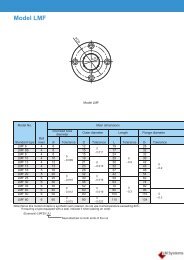
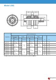
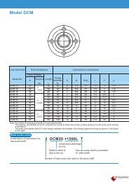
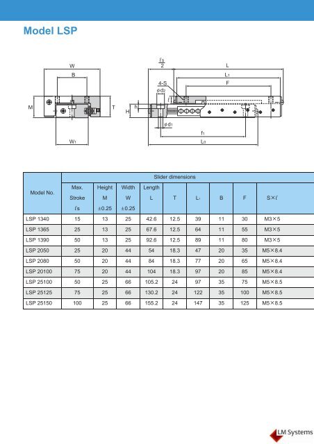
Model LSP<br />
W<br />
l S<br />
2<br />
L<br />
B<br />
L1<br />
M<br />
T<br />
H<br />
h<br />
4-S<br />
φ d2<br />
l<br />
F<br />
φ d1<br />
f1<br />
W1<br />
L0<br />
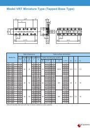
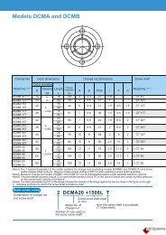
<strong>Slide</strong>r dimensions<br />
Model No.<br />
Max. Height Width Length<br />
Stroke M W L T L1 B F Sl<br />
l s ±0.25 ±0.25<br />
LSP 1340 15 13 25 42.6 12.5 39 11 30 M35<br />
LSP 1365 25 13 25 67.6 12.5 64 11 55 M35<br />
LSP 1390 50 13 25 92.6 12.5 89 11 80 M35<br />
LSP 2050 25 20 44 54 18.3 47 20 35 M58.4<br />
LSP 2080 50 20 44 84 18.3 77 20 65 M58.4<br />
LSP 20100 75 20 44 104 18.3 97 20 85 M58.4<br />
LSP 25100 50 25 66 105.2 24 97 35 75 M58.5<br />
LSP 25125 75 25 66 130.2 24 122 35 100 M58.5<br />
LSP 25150 100 25 66 155.2 24 147 35 125 M58.5
MA<br />
MB<br />
MC<br />
Unit: mm<br />
Base dimensions Static permissible moment* Basic load rating Mass<br />
Width Height Length<br />
W1 H d1d2h L0 f1<br />
MA, MB MC C C0<br />
g<br />
N-m N-m N N<br />
12.2 7.7 3.363.3 42.6 30 0.88 0.49 68.6 118 37<br />
12.2 7.7 3.363.3 67.6 55 1.76 0.98 118 206 60<br />
12.2 7.7 3.363.3 92.6 80 3.04 1.27 157 275 85<br />
22.3 11 5.395.3 54 35 1.37 2.25 157 284 114<br />
22.3 11 5.395.3 84 65 3.53 4.51 304 559 184<br />
<strong>Linear</strong> <strong>Ball</strong> <strong>Slide</strong><br />
22.3 11 5.395.3 104 85 5 5.69 392 706 231<br />
38 16 5.395.3 105.2 75 9.22 14.5 588 1069 433<br />
38 16 5.395.3 130.2 100 12.9 18.1 735 1333 547<br />
38 16 5.395.3 155.2 125 17.5 21.9 882 1598 652<br />
Note) *MA, MB and MC each indicate the permissible moment per <strong>LM</strong> system, as shown in the figure above.
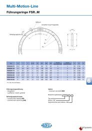
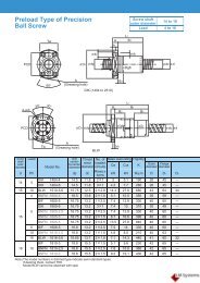
Model LS<br />
W<br />
l S<br />
2<br />
L<br />
B<br />
L1<br />
M<br />
T<br />
H<br />
h<br />
4-S<br />
φ d2<br />
l<br />
F<br />
φ d1<br />
f1<br />
W1<br />
L0<br />
<strong>Slide</strong>r dimensions<br />
Model No.<br />
Max. Height Width Length<br />
Stroke M W L T L1 B F Sl<br />
l s ±0.25 ±0.25<br />
LS 827 13 8 14.2 29.6 7.6 26 5.5 16 M22.7<br />
LS 852 25 8 14.2 54.6 7.6 51 5.5 41 M22.7<br />
LS 877 50 8 14.2 79.6 7.6 76 5.5 66 M22.7<br />
LS 1027 13 10 19 29.6 9.2 26 8.5 16 M33.2<br />
LS 1052 25 10 19 54.6 9.2 51 8.5 41 M33.2<br />
LS 1077 50 10 19 79.6 9.2 76 8.5 66 M33.2
MA<br />
MB<br />
MC<br />
Unit: mm<br />
Base dimensions Static permissible moment* Basic load rating Mass<br />
Width Height Length<br />
W1 H d1d2h L0 f1<br />
MA, MB MC C C0<br />
N-m N-m N N g<br />
6.2 4.7 2.23.91.4 29.6 19 0.2 0.29 39.2 68.6 9<br />
6.2 4.7 2.23.91.4 54.6 35 0.49 0.39 68.6 118 15<br />
6.2 4.7 2.23.91.4 79.6 60 0.88 0.59 98 167 21<br />
9.6 6.2 3.363.1 29.6 19 0.29 0.59 58.8 108 13<br />
9.6 6.2 3.363.1 54.6 35 0.78 1.08 108 186 23<br />
<strong>Linear</strong> <strong>Ball</strong> <strong>Slide</strong><br />
9.6 6.2 3.363.1 79.6 60 1.47 1.57 157 275 34<br />
Note) *MA, MB and MC each indicate the permissible moment per <strong>LM</strong> system, as shown in the figure above.
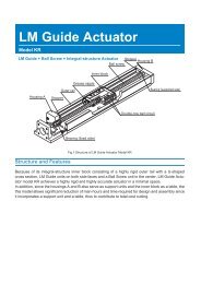
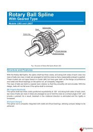
Model LSC<br />
Stroke<br />
J<br />
l S<br />
<br />
2<br />
Q<br />
12<br />
2×2-M4 depth 8<br />
4-φ m 4-Sl<br />
T<br />
5.5<br />
h H S3<br />
g1<br />
f1<br />
4-M512<br />
φ d2<br />
φ d1<br />
B W<br />
A<br />
W1<br />
B2<br />
R<br />
F2<br />
F1<br />
L<br />
G2<br />
G1<br />
2-S2l 1<br />
Hole for<br />
air piping<br />
5.5<br />
M1<br />
M<br />
g2<br />
L0<br />
f2<br />
Model No.<br />
Max.<br />
Stroke<br />
l s +0.5<br />
0<br />
Cylinder<br />
Inner diameter<br />
<strong>Slide</strong>r dimensions<br />
Theoretical<br />
thrust<br />
Height Width<br />
(at 500 kPa) M W L T B<br />
N ±0.05<br />
LSC 1015 15 10 38.2 25 50 80 24 20<br />
LSC 1515 15 15 86.3 30 70 80 21 30<br />
LSC 1530 30 15 86.3 30 70 110 21 30<br />
LSC 1550 50 15 86.3 30 70 150 21 30<br />
Model No.<br />
<strong>Slide</strong>r dimensions<br />
Base dimensions<br />
L0 B2 f2 g2 f1 g1 d1d2h A S3<br />
LSC 1015 80 20 40 20 — — 3.35.53.5 13 M4<br />
LSC 1515 80 30 40 21 23 29.5 5.295.5 17 M6<br />
LSC 1530 110 30 60 25 40 35 5.295.5 17 M6<br />
LSC 1550 150 30 100 25 78 36 5.295.5 17 M6<br />
Model number coding<br />
LSC1515 B S L<br />
Model number<br />
With unit base<br />
With external stopper<br />
With limit switch<br />
Note) Unit base, external stopper and limit switch are not available for model LSC1015.<br />
The speed controller is optional.
MA<br />
MB<br />
MC<br />
<strong>Slide</strong>r dimensions<br />
Unit: mm<br />
F1 G1 Sl m G2 F2 J Q R M1<br />
40 20 M47 5.5 12.5 40 — — — 16.5<br />
40 19 M58 9 28.5 40 29 22 4 21<br />
60 25 M58 9 35 60 44 22 4 21<br />
100 25 M58 9 50 50 64 22 4 21<br />
Base dimensions Static permissible moment* Basic load rating Mass<br />
MA, MB<br />
N-m<br />
MC<br />
C0<br />
W1 H S2l 1 kg<br />
N-m<br />
N<br />
C<br />
N<br />
<strong>Linear</strong> <strong>Ball</strong> <strong>Slide</strong><br />
31.2 5.5 M55 4.9 7.45 392 676 0.25<br />
45 10.5 M54.5 4.9 11.1 392 676 0.37<br />
45 10.5 M54.5 8.43 15.4 549 951 0.52<br />
45 10.5 M54.5 15.4 22.1 794 1350 0.72<br />
Note) *MA, MB and MC each indicate the permissible moment per <strong>LM</strong> system, as shown in the figure above.