Solar charge controller manual.pdf
Solar charge controller manual.pdf
Solar charge controller manual.pdf

Create successful ePaper yourself
Turn your PDF publications into a flip-book with our unique Google optimized e-Paper software.
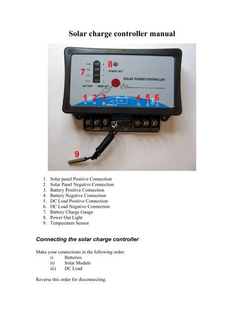
<strong>Solar</strong> <strong>charge</strong> <strong>controller</strong> <strong>manual</strong><br />
1. <strong>Solar</strong> panel Positive Connection<br />
2. <strong>Solar</strong> Panel Negative Connection<br />
3. Battery Positive Connection<br />
4. Battery Negative Connection<br />
5. DC Load Positive Connection<br />
6. DC Load Negative Connection<br />
7. Battery Charge Gauge<br />
8. Power Out Light<br />
9. Temperature Sensor<br />
Connecting the solar <strong>charge</strong> <strong>controller</strong><br />
Make your connections in the following order:<br />
i) Batteries<br />
ii) <strong>Solar</strong> Module<br />
iii) DC Load<br />
Reverse this order for disconnecting.
Connect the positive and negative leads from your solar panel(s) to 1 and 2 on the<br />
<strong>controller</strong>. Connect your battery(s) to 3 and 4 on the <strong>controller</strong> and put the temperature<br />
sensor, 9, in contact with your batteries. Connections 5 and 6 are for running a small DC<br />
load, such as a light. Do Not connect an inverter here. The solar <strong>controller</strong> will<br />
automatically shut off the power to this load and shut off the “Power Out Light” when the<br />
battery voltage gets below 10.8 volts. Power will resume when the batteries are above<br />
12.3 volts.<br />
Usage<br />
When charging the Charge Guage will sequentially blink from the bottom to the top. This<br />
will also indicate <strong>charge</strong> as the current <strong>charge</strong> level will remain lit. For example if the<br />
batteries are 50% <strong>charge</strong>d the bottom two lights will remain lit while the top two blink for<br />
charging.<br />
Troubleshooting<br />
Problem<br />
Power indicator is off, no power<br />
“CHARGING” indicator is flashing<br />
Remedy<br />
Check the fuse, maybe it is blown<br />
Batteries are connected wrong or not<br />
connected at all.<br />
Warnings<br />
1. Do not connect any power supplies or <strong>charge</strong>rs to the solar module screw connectors,<br />
otherwise the unit will be damaged.<br />
2. Ensure the solar module screw connectors and battery screw connectors are right, and<br />
not reversed polarity.<br />
3. Do not touch any “+” “-“ screw connectors of SL2410, SL2420, SL4820 at the same<br />
time, it is dangerous.
Protection Function<br />
Protection function<br />
Batteries reverse<br />
polarity<br />
<strong>Solar</strong> module reverse<br />
polarity<br />
Load over-current and<br />
short circuit protection<br />
Batteries open-circuit<br />
working protection<br />
Details<br />
Batteries reverse polarity may result in the blowing of<br />
fuse, repair as necessary and replace the fuse with an<br />
equivalent。<br />
If the solar module is connected reverse polarity, the unit<br />
will function after correction.<br />
If the load draw current exceed max. dis<strong>charge</strong> current or<br />
load short circuit, fuses will blow. Repair as necessary and<br />
replace the fuse with an equivalent.<br />
When solar module are charging, if the batteries are opencircuit,<br />
the solar <strong>controller</strong> will limit voltage, so that the<br />
load will not be damaged.<br />
Technical Specifications<br />
Model no.<br />
Parameters SL1205 SL1210 SL1220 SL2410 SL2420 SL4820<br />
Rated Voltage(VDC) 12 12 12 24 24 48<br />
Rated Current(A) 5 10 20 10 20 20<br />
Max. input Voltage(V) 25 25 25 50 50 100<br />
Over-<br />
Charge<br />
(V)<br />
Over-<br />
Dischar<br />
ge<br />
(V)<br />
Over-<br />
Protection 14.4<br />
±0.1<br />
Floating 13.8<br />
±0.1<br />
Resume 13.2<br />
±0.1<br />
Cut-off 10.8<br />
±0.1<br />
Resume 12.3<br />
±0.1<br />
14.4<br />
±0.1<br />
13.8<br />
±0.1<br />
13.2<br />
±0.1<br />
10.8<br />
±0.1<br />
12.3<br />
±0.1<br />
14.4<br />
±0.1<br />
13.8<br />
±0.1<br />
13.2<br />
±0.1<br />
10.8<br />
±0.1<br />
12.3<br />
±0.1<br />
28.8<br />
±0.2<br />
27.6<br />
±0.1<br />
23.6<br />
±0.2<br />
21.6<br />
±0.2<br />
24.6<br />
±0.2<br />
28.8<br />
±0.2<br />
27.6<br />
±0.1<br />
23.6<br />
±0.2<br />
21.6<br />
±0.2<br />
24.6<br />
±0.2<br />
57.6<br />
±0.4<br />
55.2<br />
±0.1<br />
52.8<br />
±0.4<br />
43.2<br />
±0.2<br />
49.2<br />
±0.4<br />
Cut-off 16.5 16.5 16.5 33.0 33.0 66.0<br />
Loaded Resume 15.0 15.0 15.0 30.0 30.0 60.0<br />
Voltage Between input 0.4 0.4 0.4 0.6 0.6 0.6<br />
Drop( and batteries<br />
V) Between 0.3 0.3 0.3 0.4 0.4 0.4<br />
batteries and<br />
load
No Load Current<br />