Santa Fe 1 DV 03-30-04 - Wood Heat Stoves and Solar
Santa Fe 1 DV 03-30-04 - Wood Heat Stoves and Solar
Santa Fe 1 DV 03-30-04 - Wood Heat Stoves and Solar

Create successful ePaper yourself
Turn your PDF publications into a flip-book with our unique Google optimized e-Paper software.
<strong>Santa</strong> <strong>Fe</strong><br />
(Model 8761)<br />
GAS-FIRED DIRECT VENT HEATER<br />
Owner’s Manual<br />
Operation & Installation Guide<br />
READ THIS OWNER’S MANUAL<br />
Operate <strong>and</strong> maintain this gas heater<br />
according to this instruction manual.<br />
WARNING: If the information in these instructions<br />
is not followed exactly, a fire, or explosion may<br />
result causing property damage, personal injury, or<br />
loss of life.<br />
AVERTISSEMENT: Assurez-vous de bien suivre les<br />
instructions donné dans cette notice pour réduire<br />
au minimum le risque d’incendie ou pour éviter tout<br />
dommage matéeriel, toute blessure ou la mort.<br />
• Do not store, or use gasoline, or other<br />
flammable vapors <strong>and</strong> liquids near this, or any<br />
other gas appliance!<br />
WHAT TO DO IF YOU SMELL GAS:<br />
• Do not try to light any appliance.<br />
• Do not touch electrical switches; do not use the<br />
phone in your building.<br />
• Immediately call your gas supplier from a<br />
neighbor’s phone. Follow your gas supplier’s<br />
instructions.<br />
• If you cannot reach your gas supplier, call the fire<br />
department.<br />
A qualified installer, service agency, or gas supplier<br />
must perform installation <strong>and</strong> service. In the<br />
Commonwealth of Massachusetts, all installation of<br />
gas lines <strong>and</strong> gas fitting shall only be done by a<br />
licensed gas fitter or licensed plumber.<br />
• Ne pas entresposer ni utiliser d’essence ni d’autre<br />
vaperurs ou liquides inflammables dans le<br />
voisinage de cet apprareil ou de tout autre appareil!<br />
QUE FAIRE SI VOUS SENTEZ UNE ODEUR<br />
DE GAZ:<br />
• Ne pas tenter d’allumer d’appareil.<br />
• Ne touchez à aucun interrupteur. Ne pas vous<br />
servir des téléphones se trouvant dans le<br />
batiment où vous vous trouvez.<br />
• Appelez immédiatement votre fournisseur de<br />
gaz depuis un voisin. Suivez les instructions<br />
du fournisseur.<br />
• Si vous ne pouvez rejoindre le fournisseur de<br />
gaz, appelez le service dos incendies.<br />
L’installation et service doit être exécuté par un<br />
qualifié installer, agence de service ou le<br />
fournisseur de gaz.<br />
<strong>Santa</strong> <strong>Fe</strong> Model: 8761<br />
Manual: 6400-4<strong>04</strong>51<br />
Revised: 10/2/08
Hearthstone Quality Home <strong>Heat</strong>ing Products, Inc. SANTA FE Model 8761<br />
INFORMATION SHEET<br />
Use this page to record all relevant information concerning the purchase, installation, <strong>and</strong> maintenance of your<br />
SANTA FE Gas-Fired Direct Vent <strong>Heat</strong>er. This information will facilitate servicing, purchase of replacement<br />
parts, <strong>and</strong> warranty claims (if necessary). Keep your original receipt in a safe place as proof of purchase.<br />
Serial Number:<br />
Fuel type (check one) Natural Gas Liquid Propane<br />
Sold by:<br />
Phone:<br />
Date of Purchase:<br />
Installed by:<br />
Phone:<br />
Date of Installation:<br />
Gas Supplier:<br />
Phone:<br />
Read this Owner’s Manual before installing, or operating the SANTA FE heater. Retain this manual for future<br />
reference.<br />
SERVICE RECORD<br />
Date Who Performed Work Work Performed Notes:<br />
WHAT WHEN WHAT WHEN<br />
Firebox Cleaning............. annually Door Gasket.................... Replacement as needed<br />
Glass Cleaning................ as needed<br />
1
Hearthstone Quality Home <strong>Heat</strong>ing Products, Inc. SANTA FE Model 8761<br />
WELCOME<br />
Congratulations on your purchase of<br />
Hearthstone’s <strong>Santa</strong> <strong>Fe</strong> Gas-Fired Direct Vent<br />
heater. The <strong>Santa</strong> <strong>Fe</strong> incorporates the latest in<br />
balanced vent gas technology, which will<br />
provide you with clean, efficient heat for years<br />
to come. Combustion air comes directly from<br />
the outside of your home to the sealed firebox<br />
system, eliminating the potential for annoying<br />
back drafts or other problems associated with<br />
home depressurization. The combination of<br />
natural stones with cast iron give the <strong>Santa</strong> <strong>Fe</strong> a<br />
pleasing look, which can be maintained with<br />
minimum care.<br />
The <strong>Santa</strong> <strong>Fe</strong> will provide you with years of<br />
practical <strong>and</strong> convenient service. However, as<br />
with any gas appliance, the unit must be<br />
properly installed, <strong>and</strong> maintained by qualified<br />
service personnel to ensure safe <strong>and</strong> trouble-free<br />
operation.<br />
READ THIS OWNER’S MANUAL<br />
Operate <strong>and</strong> maintain this gas heater according<br />
to the instructions in this manual. Read this<br />
manual in its entirety.<br />
THIS HEATER MUST BE INSTALLED AND<br />
MAINTAINED BY QUALIFIED SERVICE<br />
PERSONNEL<br />
Verify the gas connections, <strong>and</strong> venting systems<br />
with requirements of local, regional, or national<br />
installation codes. Qualified service personnel<br />
must inspect the gas heater before use, <strong>and</strong> at<br />
least annually.<br />
ALWAYS VENT TO THE OUTSIDE<br />
Never vent the gas heater to other rooms, or<br />
buildings. Do not connect this gas appliance to a<br />
chimney flue serving a separate solid-fuel<br />
burning appliance.<br />
MANUFACTURED BY:<br />
Hearthstone Quality Home <strong>Heat</strong>ing Products, Inc.<br />
317 Stafford Avenue<br />
Morrisville, Vermont 05661-8695<br />
USA<br />
TABLE OF CONTENTS<br />
WELCOME .................................................. 2<br />
OWNER’S INFORMATION............................ 3<br />
DAILY OPERATIONS................................. 4<br />
INSTALLER’S INFORMATION ...................... 5<br />
UNPACKING AND INSPECTION .................. 5<br />
STOVE DIMENSIONS & CLEARANCES TO<br />
COMBUSTIBLES........................................ 6<br />
VENTING INFORMATION........................... 9<br />
VENT CONNECTION.................................. 9<br />
APPROVED VENTING SYSTEM<br />
COMPONENTS ........................................ 11<br />
GAS CONNECTIONS................................ 16<br />
REPLACING THE GLASS.......................... 17<br />
LOG PLACEMENT ................................... 17<br />
INSTALLATION OF THE LOG SET............. 17<br />
REMOVAL OF LOG SET........................... 18<br />
LIGHTING THE UNIT THE FIRST TIME..... 18<br />
INITIAL ADJUSTMENTS........................... 19<br />
AIR SHUTTER ADJUSTMENTS ................. 19<br />
GAS CONVERSIONS ................................ 20<br />
ROUTINE MAINTENANCE AND CARE ....... 20<br />
PARTS LISTS .......................................... 22<br />
TROUBLESHOOTING GUIDE ........... 24<br />
LIMITED WARRANTIES ................... 27<br />
WARNING!<br />
A qualified service technician should do<br />
installation, <strong>and</strong> repair. A qualified service<br />
technician must inspect the appliance before<br />
use, <strong>and</strong> at least annually. More frequent<br />
cleaning may be required due to excessive lint<br />
from carpeting, bedding material, pets, etc. It<br />
is imperative that the control compartments,<br />
burners, <strong>and</strong> circulating air passages of the<br />
appliance are kept clean <strong>and</strong> free of<br />
obstructions. (S’assurer que le brûleur et le<br />
compartiment des comm<strong>and</strong>es sont propres.<br />
Voir les instructions d’installation et<br />
d’utilisation qui accompagnent l’appareil.)<br />
2
Hearthstone Quality Home <strong>Heat</strong>ing Products, Inc. SANTA FE Model 8761<br />
SERVICE CAUTION<br />
Any components of the stove removed for<br />
servicing must be replaced before operating. If<br />
you believe your <strong>Santa</strong> <strong>Fe</strong> is not performing<br />
properly, immediately discontinue operation<br />
until the unit is inspected <strong>and</strong> approved for<br />
operation by qualified service personnel. Prior to<br />
servicing the unit, turn the valve control knob<br />
clockwise to “OFF”. Ensure the unit is cool<br />
before servicing <strong>and</strong> cleaning.<br />
• WARNING! Any safety screen, guard, or<br />
component removed during servicing<br />
must be replaced before operation.<br />
Do not use any components other than those<br />
approved by Hearthstone Quality Home<br />
<strong>Heat</strong>ing Products, Inc., otherwise all<br />
warranties are void. Do not substitute<br />
components!<br />
FIRE HAZARD<br />
Do not store, or use gasoline, or other flammable<br />
vapors or liquids near this appliance. The <strong>Santa</strong><br />
<strong>Fe</strong> should be located out of traffic, <strong>and</strong> away<br />
from furniture, draperies, clothing, <strong>and</strong> other<br />
flammable materials.<br />
SHOCK HAZARD (IF EQUIPPED WITH ACCESSORY FAN)<br />
The accessory blower is equipped with a threeprong<br />
(grounding) plug for protection against<br />
shock hazard <strong>and</strong> must be plugged directly into a<br />
properly grounded three-prong receptacle. Do<br />
not cut, or remove, the grounding prong from<br />
the plug.<br />
HOT SURFACES<br />
Certain exposed surfaces of the <strong>Santa</strong> <strong>Fe</strong> will<br />
reach high temperatures during normal<br />
operation. Clearances to combustibles must be<br />
maintained, as specified in the “Clearances To<br />
Combustibles” section of this manual. Due to<br />
high temperatures, the appliance should be<br />
located out of traffic <strong>and</strong> away from<br />
furniture, draperies, clothing, <strong>and</strong> other<br />
flammable materials. Alert children <strong>and</strong><br />
adults to the hazards of high surface<br />
temperatures <strong>and</strong> that they must stay away to<br />
avoid burns to skin or possible clothing<br />
ignition. Supervise young children carefully<br />
3<br />
when in the same room as the appliance. Do<br />
not place clothing or other flammable<br />
material on or near the appliance. (Surveille<br />
les enfants. Garder les vêtements, les meubles,<br />
l’essence ou autres liquides à vapeur<br />
inflammables lin de l’appareil.) Clean the area<br />
around, under, <strong>and</strong> behind the unit on a regular<br />
basis to prevent the accumulation of dust <strong>and</strong><br />
lint.<br />
• WARNING! Do not operate the appliance<br />
with the front glass removed, cracked, or<br />
broken. Replacement of glass should be<br />
done by a licensed, or qualified service<br />
person. Only open front for routine<br />
service. Do not slam, or strike the glass.<br />
OWNER’S INFORMATION<br />
The installation must conform with local codes<br />
or, in the absences of local codes, the current<br />
National Fuel Gas Code, ANSI Z223.1 (NFPA<br />
54), or CAN/CGA B149 Installation Code.<br />
(Installer l’appareil selon les codes ou<br />
règlements locaux, ou, en l’absence de tels<br />
règlements, selon les Codes d’installation<br />
CAN/CGA-B149.)<br />
Do not use this appliance if any part was<br />
under water. Immediately call a qualified<br />
service technician to inspect the heater, <strong>and</strong><br />
to replace any part of the control system that<br />
was submerged. (NE PAS SE SERVIR DE CET<br />
APPAREIL S’IL A ÉTÉ PLONGÉ DANS L’EAU,<br />
COMPLÈTEMENT OU EN PARTIE. APPELER UN<br />
TECHNICIEN QUALIFIÉ POUR INSPECTOR<br />
L’APPAREIL ET REMPLACER TOUTE PARTIE DU<br />
SYSTÈME DE CONTRÔLE ET TOUTE COMMANDE<br />
QUI ONT ÉTÉ PLONGÉS DANS L’LAU.)<br />
Certified for use by:<br />
Board of State Examiners of Plumbers <strong>and</strong> Gasfitters<br />
100 Cambridge Street, Room 1511<br />
Boston, Massachusetts<br />
02202
Hearthstone Quality Home <strong>Heat</strong>ing Products, Inc. SANTA FE Model 8761<br />
LIGHTING INSTRUCTIONS<br />
1. Set the on/off/T-stat switch or thermostat to<br />
the off position.<br />
2. Unplug the blower accessory, if so equipped.<br />
3. Push in <strong>and</strong> turn gas control knob clockwise<br />
to “OFF”. (If not previously lit, the knob<br />
should be in this position.)<br />
4. Wait (5) five minutes to clear out any gas.<br />
If you then smell gas, STOP! Smell all<br />
around the appliance area for gas. Be sure<br />
to smell next to the floor because some<br />
gases (LPG) are heavier than air <strong>and</strong> will<br />
settle on the floor. If you smell gas<br />
immediately, follow the What To Do If You<br />
Smell Gas! warning on the cover of this<br />
Manual. If you do not smell gas, go to the<br />
next step.<br />
5. Turn gas control knob counterclockwise to<br />
“PILOT”.<br />
6. Push in control knob all the way <strong>and</strong> hold in.<br />
Immediately light the pilot with the gas<br />
lighter (push in <strong>and</strong> “click” the piezoelectric<br />
spark igniter button several times until lit).<br />
Continue to hold the control knob in for<br />
about 20 seconds after the pilot is lit.<br />
Release the knob <strong>and</strong> it will pop back out.<br />
Pilot should remain lit. If the pilot goes out,<br />
repeat the operation.<br />
• If knob does not pop out when released,<br />
stop <strong>and</strong> immediately call a qualified<br />
service technician or gas supplier.<br />
• If the pilot will not stay lit after several<br />
tries, turn the gas control knob “OFF”<br />
<strong>and</strong> call a qualified service technician or<br />
gas supplier.<br />
7. Turn gas control knob counterclockwise to<br />
“ON”.<br />
8. Select “ON” or “T-STAT” position on the<br />
on/off/t-stat switch.<br />
9. Shut the gas control valve access door.<br />
10. Plug in the blower accessory, if so equipped.<br />
11. Set thermostat to “ON” <strong>and</strong> set the desired<br />
temperature setting.<br />
TO TURN OFF THE GAS TO THE APPLIANCE<br />
Turn the gas control knob clockwise to “OFF”<br />
position. If shutting the unit off for the nonheating<br />
season, this will improve the overall<br />
efficiency of the unit as the heat from the pilot is<br />
wasted in the summer. When putting the unit<br />
back into service follow the lighting instructions<br />
described on this page.<br />
VARIABLE OUTPUT CONTROL<br />
The gas control valve is equipped with a<br />
variable output control. This control varies the<br />
rate of heat produced by the unit by varying the<br />
gas pressure to the main burner tube.<br />
DAILY OPERATIONS<br />
The homeowner easily operates the <strong>Santa</strong> <strong>Fe</strong><br />
gas-fired heater. The unit comes with a st<strong>and</strong>ard<br />
thermostat. Remote thermostats, or wall<br />
switches are available for purchase from your<br />
local Hearthstone dealer. Once the thermostat is<br />
installed <strong>and</strong> properly adjusted, the desired room<br />
temperature is maintained. By adjusting the<br />
variable output control located on the gas control<br />
valve, the rate of heat output can be varied to<br />
meet the heating requirements of the season.<br />
Choosing a low flame setting will result in<br />
longer burn cycles at a reduced output, while<br />
choosing a high flame setting will result in a<br />
shorter, hotter burn cycle. Through trial <strong>and</strong><br />
error, the homeowner can select the optimum<br />
flame size for their setting, <strong>and</strong> application. Also<br />
available is a variable speed blower. (Kit# 93-<br />
57010)<br />
Normally, if the “T-STAT” position was<br />
selected, the main burner is cycled on <strong>and</strong> off by<br />
the Thermostat or the “on”, “off” switch located<br />
on the bottom of the Thermostat body.<br />
4
Hearthstone Quality Home <strong>Heat</strong>ing Products, Inc. SANTA FE Model 8761<br />
INSTALLER’S<br />
INFORMATION<br />
Codes<br />
Adhere to ALL local codes or, in their absence,<br />
the latest edition of THE NATIONAL FUEL<br />
GAS CODE ANSI Z223.1 (NFPA 54) or<br />
CAN/CGA B149 Installation Code, which can<br />
be obtained from:<br />
AMERICAN NATIONAL STANDARDS<br />
INSTITUTE, INC.<br />
14<strong>30</strong> BROADWAY<br />
NEW YORK, NY 10018<br />
OR<br />
NATIONAL FIRE PROTECTION<br />
ASSOCIATION, INC.<br />
BATTERY MARCH PARK<br />
QUINCY, MA 02269<br />
The appliance when installed, must be<br />
electrically connected <strong>and</strong> grounded in<br />
accordance with local codes or, in the absence of<br />
local codes, with the current NFPA 70-National<br />
Electrical Code or CSA C22.1-Canadian Electric<br />
Code.<br />
A manufactured home (mobile) OEM<br />
installation must conform with the Manufactured<br />
Home Construction <strong>and</strong> Safety St<strong>and</strong>ard, Title<br />
24 CFR, Part 3280 (U.S.) or St<strong>and</strong>ard for<br />
Manufactured Home Installation, ANSI/NCBCS<br />
A225.1 or St<strong>and</strong>ard for Gas Equipped<br />
Recreational Vehicles <strong>and</strong> mobile Housing, CSA<br />
Z240.4.CAN/SCA Z240 MH (Canada).<br />
(Installer l’appareil selon les codes ou<br />
règlements locaux, ou, en l’absence de tels<br />
règlements, selon les Codes d’installation<br />
CAN/CGA-B149.)<br />
For installations from 610-1370 meters (2000-<br />
4500 ft.) the orifice sizes (DMS) for natural <strong>and</strong><br />
propane gas are 32 <strong>and</strong> 52 respectively. See<br />
data plate for additional information. For high<br />
altitude installations consult the local gas<br />
distributor or the authority having jurisdiction<br />
for proper rating methods. If the installer must<br />
convert the unit to adjust for varying altitudes,<br />
5<br />
the information sticker must be filled out by the<br />
installer <strong>and</strong> adhered to the appliance at the<br />
same time of conversion. (Cet appareil est<br />
equipè pour des altitudes compries entre 0 et<br />
2000 pieds (0-610 m) seulement.)<br />
FIBER LOG SAFETY INFORMATION<br />
If the decorative fiber logs supplied with the<br />
<strong>Santa</strong> <strong>Fe</strong> are damaged, they must be replaced.<br />
Hearthstone supplies replacement parts through<br />
your local Hearthstone dealer. Do not replace<br />
fiber logs, or the embers, with any materials not<br />
approved by Hearthstone Quality Home <strong>Heat</strong>ing<br />
Products, Inc.<br />
UNPACKING AND INSPECTION<br />
Unpack <strong>and</strong> Inspect for Damage<br />
The <strong>Santa</strong> <strong>Fe</strong> is packaged by the manufacturer to<br />
withst<strong>and</strong> normal shipment without damage.<br />
However, damage can still occur during transit,<br />
so take care to inspect for damage when<br />
unpacking <strong>and</strong> installing the unit. If any damage,<br />
or a missing part, is detected, immediately<br />
contact your dealer. Do not install or put into<br />
service a damaged or incomplete heater.<br />
The unit should appear to be square <strong>and</strong> level.<br />
The sheet metal parts should be smooth <strong>and</strong> free<br />
of bends or dents. The enameled cast iron<br />
should be free of chips or cracks. If visible, or<br />
concealed damage is found, contact your dealer.<br />
The decorative fiber logs supplied with the <strong>Santa</strong><br />
<strong>Fe</strong> are located in the firebox. Always use great<br />
care when h<strong>and</strong>ling the decorative ceramic logs,<br />
as they are very fragile <strong>and</strong> subject to damage<br />
<strong>and</strong> breakage. To open the firebox: remove the<br />
front door screw with the supplied Allen<br />
wrench, take care not to chip the enamel, <strong>and</strong><br />
swing the door open. Remove the lag bolts,<br />
which fasten the unit to the pallet. Take care not<br />
to chip the enameled legs. Have someone help<br />
lift the stove off the pallet, <strong>and</strong> set it into place.
Hearthstone Quality Home <strong>Heat</strong>ing Products, Inc. SANTA FE Model 8761<br />
Packing List<br />
1-<strong>Santa</strong> <strong>Fe</strong> Gas-fired <strong>Heat</strong>er containing:<br />
5-Decorative Ceramic Logs<br />
1-Pan Burner<br />
1-Owner’s Manual <strong>and</strong> Warranty<br />
Charcoal Embers (with Rock Wool)<br />
1-Accessory box containing:<br />
1- 1/8” Allen key for front door<br />
1-Ash Lip<br />
1-Top Grille<br />
1-Thermostat with Thermostat Wire<br />
2-Extension control Knobs<br />
1-LP Conversion kit<br />
2-Stone Clips<br />
HEARTH REQUIREMENT/FLOOR PROTECTION<br />
The <strong>Santa</strong> <strong>Fe</strong> can be placed on a noncombustible<br />
surface, or wood floor. For<br />
placement of the <strong>Santa</strong> <strong>Fe</strong> on carpeting, vinyl<br />
tile, or other combustible materials, the<br />
appliance must be installed on a metal or wood<br />
panel extending the full width <strong>and</strong> depth of the<br />
appliance. Installations must meet all codes.<br />
ITEMS REQUIRED FOR INSTALLATION<br />
* External regulator (for propane/L.P.G. only)<br />
* Piping which complies with all codes<br />
* Pipe sealant approved for use with<br />
propane/L.P.G. (resistant to sulfur compounds)<br />
* Manual shutoff valve<br />
* Sediment trap (page 16)<br />
* Tee joint<br />
* Pipe wrench<br />
* Phillips head screwdriver<br />
* Other parts as required by local code<br />
*Safety Glasses<br />
*Gloves<br />
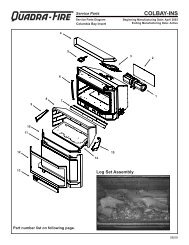
26 3/4"<br />
25"<br />
HearthStone<br />
AIR SUPPLY<br />
The <strong>Santa</strong> <strong>Fe</strong> Direct-vent does not require<br />
additional installer provided ventilation<br />
Figure 1 - <strong>Santa</strong> <strong>Fe</strong> Dimensions<br />
STOVE DIMENSIONS & CLEARANCES TO<br />
COMBUSTIBLES<br />
Always maintain clearances around the air<br />
openings in the stove. This allows for adequate<br />
ventilation. (as shown in Figures 3, & 4.)<br />
6
Hearthstone Quality Home <strong>Heat</strong>ing Products, Inc. SANTA FE Model 8761<br />
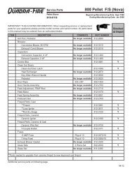
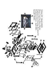
Figure 2 - <strong>Santa</strong> <strong>Fe</strong> Dimensions<br />
3 1/8"<br />
25 "<br />
23 3/4"<br />
22"<br />
21"<br />
21 3/4"<br />
CLEARANCE TO COMBUSTIBLES<br />
17" max.<br />
2" MIN.<br />
1" MIN.<br />
2" MIN.<br />
14" MIN.<br />
4" MIN.<br />
Figure 3 - Rear <strong>and</strong> side wall clearances<br />
The corner clearance for the <strong>Santa</strong> <strong>Fe</strong> is<br />
2”, to be measured from the edge of the<br />
top castings to the adjacent wall.<br />
Figure 4 - Top clearances (not to scale)<br />
7
Hearthstone Quality Home <strong>Heat</strong>ing Products, Inc. SANTA FE Model 8761<br />
SPECIFICATIONS:<br />
LISTED: DIRECT VENT GAS HEATER<br />
Model: 8761-<strong>Santa</strong> <strong>Fe</strong> 1 <strong>DV</strong><br />
Testing Agency: Intertek<br />
Testing Services NA, Inc. (ITS)<br />
Tested to: ANSI Z21.88-<br />
2002•CSA 2.33-M02<br />
CAN/CGA 2.17<br />
Fuel type NG LP<br />
Input rating (Btu/hr) 0-2000 ft 35,000 35,000<br />
Input rating (Btu/hr) 2000-4500 ft 35,000 33,<strong>30</strong>0<br />
Orifice size DMS 0-2000 ft 32 51<br />
Orifice size DMS 2000-4500 ft 32 52<br />
Man. press.-LO setting<br />
1.2/0.3 3.3/0.8<br />
(in.w.c./kPa)<br />
Man. press.-HI setting<br />
3.5/0.87 10.0/2.48<br />
(in.w.c./kPa)<br />
Inlet press.-LO<br />
5.0/1.24 11.0/2.88<br />
setting(in.w.c./kPa)<br />
Inlet press.-HI setting(in.w.c./kPa) 7.0/1.74 13.0/3.22<br />
Minimum input rating rating 21,500 20,400<br />
(Btu/hr)<br />
Maximum output (Btu/hr) 0-2000<br />
ft<br />
25,600 25,600<br />
8
Hearthstone Quality Home <strong>Heat</strong>ing Products, Inc. SANTA FE Model 8761<br />
VENTING INFORMATION<br />
There are many configurations of vent<br />
installations for your stove. Please review<br />
the following pages for the venting<br />
installation that works best for you.<br />
Note: Vent terminals must not be recessed into<br />
walls, or siding<br />
VENT CONNECTION<br />
1. The <strong>Santa</strong> <strong>Fe</strong> 1 Direct Vent is approved for<br />
installation only with the vent connecting<br />
components listed on this page <strong>and</strong> Simpson<br />
Dura-Vent Direct Vent GS, AmeriVent Direct,<br />
EXCELDirect or Secure Vent systems. Use the<br />
following instructions along with the pipe<br />
manufacturer’s instructions to complete the<br />
installation.<br />
2. Attach the inner starter collar <strong>and</strong> gasket to<br />
the unit with the eight # 8 x ½" Phillips Head<br />
sheet metal screws.<br />
3. Place the outer starter collar <strong>and</strong> gasket onto<br />
the back of the stove. Secure the outer adapter<br />
with the eight # 8 x ½" Phillips Head sheet<br />
metal screws that are provided. Install the rest of<br />
the vent system according to the manufacturer’s<br />
instructions.<br />
Figure 5<br />
1. Gasket 4”<br />
2. Inner starter<br />
3. Gasket<br />
4. Outer Starter<br />
9
Hearthstone Quality Home <strong>Heat</strong>ing Products, Inc. SANTA FE Model 8761<br />
Approved Possible Vent TERMINATION locations.<br />
10
Hearthstone Quality Home <strong>Heat</strong>ing Products, Inc. SANTA FE Model 8761<br />
Note: The St<strong>and</strong>ard Horizontal Vent Kit does<br />
not require a restrictor.<br />
The vent/air intake termination clearances above<br />
the high side of an angled roof as follows:<br />
Roof Pitch <strong>Fe</strong>et Meters<br />
Flat to 6/12 1 0.3<br />
7/12 to 9/12 2 0.6<br />
10/12 to 12/12 4 1.2<br />
13/12 to 16/12 6 1.8<br />
17/12 to 21/12 8 2.4<br />
Figure 6<br />
APPROVED VENTING SYSTEM<br />
COMPONENTS<br />
Component Description<br />
90 0 Elbow<br />
45 0 Elbow<br />
6" Straight<br />
9" Straight<br />
12" Straight<br />
24" Straight<br />
36" Straight<br />
48" Straight<br />
11"-14 5/8" Adjustable Pipe Length<br />
Horizontal Vent Cap<br />
Vertical Vent Cap<br />
Snorkel 36”<br />
Vinyl Siding St<strong>and</strong>off 4 x 6 5/8”<br />
Round Ceiling Support Wall<br />
Thimble Covers<br />
Wall thimble<br />
If the vent air intake system, for any reason,<br />
is disassembled, it must be reinstalled per the<br />
instructions provided for in the initial<br />
installation or in this manual.<br />
turn clockwise until the two sections are fully<br />
locked. Install the 90º elbow in similar fashion.<br />
NOTE: BE SURE THERE IS NO WIRING OR<br />
PLUMBING IN THE CHOSEN WALL LOCATION.<br />
Move the stove <strong>and</strong> pipe assembly back until the<br />
90º elbow is flush to the wall. The 2’vertical<br />
pipe should be parallel to the wall. Draw a<br />
circle around the pipe. Use the center of this<br />
circle as the center point of the 10” x 10” square<br />
wall pass through. Cut <strong>and</strong> frame the wall for<br />
the vent pipe. Install the horizontal vent<br />
termination on the outside of the wall. Make<br />
sure both of the retaining straps extend through<br />
the interior wall. Before attaching the vent<br />
termination to the outside of the house, run a<br />
bead of non-hardening mastic around the outside<br />
edges, between the vent termination <strong>and</strong> the<br />
wall. The arrow on the end cap should point up.<br />
Secure the cap to the wall with the appropriate<br />
screws.<br />
Put the adjustable (11”-14”) pipe into the<br />
horizontal vent cap, (the vent pipe must extend<br />
into the horizontal vent cap a minimum of 1 ¼”).<br />
Move the stove <strong>and</strong> vent pipe into position,<br />
insert the adjustable (11”-14”) pipe into the 90Ε<br />
elbow, twist lock it. Secure the straps from the<br />
horizontal vent termination to the interior pipe<br />
with two sheet metal screws, keeping screws as<br />
close to the wall thimble as possible. Bend or<br />
cut the excess strapping so the thimble cover<br />
will fit properly. Screw the thimble cover to the<br />
wall.<br />
• The adjustment range of the wall<br />
thickness for this configuration is<br />
3”min- 9”max.<br />
VENT CONFIGURATION OPTIONS<br />
I. STANDARD HORIZONTAL INSTALLATION<br />
Kit #93-65000)<br />
Minimum horizontal run is 9”<br />
NOTE:<br />
Install the 45º elbow over the outer collar. Place<br />
the elbow so that the twist lock end is pointing<br />
up. Install the 2’ pipe section into the elbow by<br />
fully inserting it, <strong>and</strong> turning approximately ¼<br />
11
Hearthstone Quality Home <strong>Heat</strong>ing Products, Inc. SANTA FE Model 8761<br />
VENT RESTRICTOR<br />
To adjust your restrictor for maximum flame<br />
appearance, loosen the Phillips head screw <strong>and</strong><br />
spin the locator, found on the rear left side of the<br />
stove. (Refer to figure 7)<br />
Figure 7<br />
II. FIREPLACE VENTING INSTALLATIONS<br />
-40' maximum system height (without offsets)<br />
-14' maximum offset (refer to Figures 8-9)<br />
-Maximum rise to run = 1 to 5 (refer to Figures8-9)<br />
-The termination must fall within the area outlined in Figure 8 <strong>and</strong> the Chart in Figure 7.<br />
-Minimum horizontal run of 9”<br />
12
Hearthstone Quality Home <strong>Heat</strong>ing Products, Inc. SANTA FE Model 8761<br />
III. VERTICAL TERMINATION VENTING CONFIGURATIONS<br />
-40' maximum system height (without offsets)<br />
Figure 8<br />
13
Hearthstone Quality Home <strong>Heat</strong>ing Products, Inc. SANTA FE Model 8761<br />
Figure 9<br />
IV. Horizontal Termination Venting<br />
Configurations<br />
-A minimum of 24" rise is required (with or w/o<br />
offsets)<br />
-40' maximum system height (without offsets)<br />
-Maximum rise to run = 1 to 5 (refer to Figures<br />
8 & 9)<br />
-The termination must fall within the area<br />
outlined by the shaded area shown in Figure 7.<br />
Use a vinyl siding St<strong>and</strong> off when installing<br />
against vinyl siding.<br />
-Horizontal sections require a 1/4" rise every 12"<br />
of horizontal run.<br />
-For each 90 0 elbow after the second, remove 5'<br />
from horizontal run.<br />
-Use with snorkel termination 45" maximum<br />
horizontal run.<br />
-Minimum horizontal run is 9”.<br />
The Authority Having Jurisdiction must be consulted before<br />
proceeding with these installation methods.<br />
14
Hearthstone Quality Home <strong>Heat</strong>ing Products, Inc. SANTA FE Model 8761<br />
Figure 10 Approved <strong>DV</strong> Venting Configurations for Horizontal Termination<br />
Conditionally approved for purchased mobile<br />
home installation. This appliance may be<br />
installed in an aftermarket permanently<br />
located, manufactured (mobile) home, where<br />
prohibited by local codes.<br />
This appliance is only for use with the type of<br />
gas indicated on the rating plate. This<br />
appliance is not convertible for use with other<br />
gases, unless a certified kit is used, available<br />
through your local Hearthstone dealer.<br />
Cet appareil peut être installé dans un maison<br />
préfabriquée (mobile) déjà installée à demeure<br />
si les règlements locaux le permettent.<br />
Cet appareil doit être utilisé uniquement avec<br />
les types de gas indiqués sur la plaque<br />
signalétique. Ne pas l’utiliser avec d’autres gas<br />
sauf si un kitde conversion certifié est installé<br />
15
Hearthstone Quality Home <strong>Heat</strong>ing Products, Inc. SANTA FE Model 8761<br />
Figure 11<br />
GAS CONNECTIONS<br />
The gas supply line connection is made to the<br />
<strong>Santa</strong> <strong>Fe</strong>’s gas control valve located under the<br />
unit on the left side using a 3/8" NPT fitting.<br />
The pipe must be sized to provide sufficient gas<br />
supply to meet the maximum dem<strong>and</strong> of the<br />
unit. The supply line must include a manual<br />
shut-off valve <strong>and</strong> union so that the unit can be<br />
disconnected for servicing.<br />
Use of a dedicated sediment trap is required by<br />
code, <strong>and</strong> by Hearthstone. Damage to<br />
components caused by the lack of a sediment<br />
trap is not covered by warranty.<br />
Once connected to the gas supply, the gas inlet<br />
pressure, <strong>and</strong> manifold gas pressure, must be<br />
tested. The gas control valve has built in<br />
pressure taps for test gauge connections. The<br />
supply line pressure must be tested to ensure it<br />
meets the minimum pressure for the type of fuel<br />
in use (NG or LP).<br />
Pressure Measurements: To measure the gas<br />
pressures, connect a manometer to the gas inlet<br />
tap (6) <strong>and</strong> manifold pressure tap (7) in Figure<br />
11.<br />
16<br />
To Equipment<br />
Inlet<br />
SEDIMENT TRAP<br />
Nipple<br />
Cap<br />
Gas Supply<br />
Inlet<br />
Tee Fitting<br />
3" MIN.<br />
GAS PRESSURE ADJUSTMENT<br />
A qualified technician must connect the heater to<br />
the gas supply, <strong>and</strong> leak test the unit before it is<br />
approved for use. Consult all applicable codes.<br />
The appliance, <strong>and</strong> its main gas valve, must be<br />
isolated from the gas supply piping system by<br />
closing its individual manual shutoff valve<br />
during any pressure testing of the gas supply<br />
piping system at test pressures equal to or<br />
greater than ½ psig (3.5kPa).
HearthStone Quality Home <strong>Heat</strong>ing Products Inc<br />
SANTA FE 1 Gas-Fired Direct Vent heater<br />
REPLACING THE GLASS<br />
To replace the front glass, shut the pilot light off.<br />
Remove the front screw, using the 1/8” hex<br />
wrench provided. Open the door. Take care <strong>and</strong><br />
pull the door up <strong>and</strong> remove it from its hinges.<br />
Remove the eight Phillips head screws in the<br />
frame <strong>and</strong> pull the frame <strong>and</strong> glass off the door.<br />
If the glass is broken, pull the broken fragments<br />
of glass away from the door using heavy-duty<br />
gloves, as the pieces will be very sharp.<br />
Carefully replace the glass gasket as necessary,<br />
<strong>and</strong> replace the door.<br />
the enamel when loosening the bolt. Pull<br />
the door open by grabbing the top edge of<br />
the doorframe.<br />
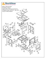
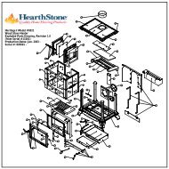
WHEN INSTALLING THE LOGS BE<br />
SURE NOT TO COVER ANY SLOTTED<br />
PORTS ON THE BURNER SURFACE<br />
2. Remove the packaging material around<br />
the log set assembly. Be careful not to damage<br />
the log set when unpacking. Observe the 5<br />
mounting “posts”, A, B, C, D, <strong>and</strong> E.<br />
• WARNING! Do not use substitute<br />
materials. Use only parts that have been<br />
supplied by Hearthstone, through an<br />
authorized Hearthstone dealer.<br />
• CAUTION! Do not clean the glass while<br />
the unit is hot. Allow approximately one<br />
hour before attempting cleaning.<br />
LOG PLACEMENT<br />
Place only the decorative ceramic log set<br />
supplied with the unit in the firebox. This log set<br />
is specifically designed to work with the<br />
provided pan burner. Do not use any other type<br />
of ceramic logs, wood logs, or other materials in<br />
the firebox. If the original log set is damaged, or<br />
broken, contact your Hearthstone dealer for<br />
replacement. The decorative ceramic log set will<br />
last a long time, however, they will break easily<br />
if subjected to rough or improper h<strong>and</strong>ling.<br />
Exact positioning of the log set is required in<br />
order to obtain a pleasing flame pattern <strong>and</strong><br />
efficient combustion. Incorrect log placement<br />
can cause carbon build-up; excess thermal stress<br />
on the log set <strong>and</strong> stove parts, reduced<br />
efficiency, <strong>and</strong> high levels of carbon monoxide.<br />
If the log set does not fit into the firebox exactly<br />
as outlined, contact your dealer for assistance.<br />
INSTALLATION OF THE LOG SET<br />
(Refer to the figures in this section)<br />
Caution-Do not place embers near the pilot.<br />
1. Open the front door using a 1/8” hex<br />
wrench. Loosen the bolt that fastens the<br />
doorknob to the door. It also unfastens the<br />
door from the firebox by turning it<br />
counterclockwise. Be careful not to chip<br />
3. Gently slide the Y-shaped Log (1) onto<br />
pins A <strong>and</strong> C, as shown below.<br />
4. Gently slide the longer, “half” log (2)<br />
onto pin D. Be sure to position the rear of the<br />
log in front of the pilot assembly <strong>and</strong> against<br />
the left side of the firebox as shown below.<br />
5. Gently slide the shortest of the “half”<br />
logs (3) onto pin B as shown below.<br />
17
HearthStone Quality Home <strong>Heat</strong>ing Products Inc<br />
SANTA FE 1 Gas-Fired Direct Vent heater<br />
6. Gently slide the medium length of<br />
the “half” logs (4) onto pin E as shown<br />
below.<br />
Figure 12<br />
9. With a 1/8" hex head wrench, use the<br />
bolt to fasten the door to the firebox. Make<br />
sure the door is properly secured to the firebox<br />
before lighting the unit. Be careful not to chip<br />
the enamel when fastening the door.<br />
REMOVAL OF LOG SET<br />
7. Gently slide the long unbroken log<br />
(5) onto pins C <strong>and</strong> D as shown below.<br />
• Caution! Log set <strong>and</strong> charcoal embers<br />
will retain heat <strong>and</strong> can be very hot, if<br />
previously lit! Allow at least 1 hour<br />
after pilot light is turned off before<br />
h<strong>and</strong>ling.<br />
To remove the log set, follow the<br />
Installation of Log Set instructions in the<br />
reverse order.<br />
• Caution! Fragile! H<strong>and</strong>le log set <strong>and</strong><br />
charcoal embers with care.<br />
LIGHTING THE UNIT THE FIRST TIME<br />
8. Spread evenly across the front portion of<br />
the Pan Burner, one layer high, the Charcoal<br />
Embers. You may or may not need to use all of<br />
the Charcoal Embers. Keep the rest for use<br />
in the future. Locate <strong>and</strong> open the bag of rock<br />
wool. Pull apart small pieces of the wool <strong>and</strong><br />
sprinkle over the Charcoal Embers r<strong>and</strong>omly.<br />
This wool will glow once the unit is running.<br />
SMOKE AND FUMES WARNING<br />
When lit for the first time, the <strong>Santa</strong> <strong>Fe</strong> will emit<br />
some smoke <strong>and</strong> odors. This is normal “offgassing”<br />
of the paints <strong>and</strong> oils used in the<br />
manufacturing, <strong>and</strong> assembly of the unit. Open<br />
windows to vent the room if necessary. The off<br />
gassing <strong>and</strong> fumes will subside after the first 10<br />
to 20 minutes of operation.<br />
Once the <strong>Santa</strong> <strong>Fe</strong> is set in place <strong>and</strong> connected<br />
as described previously, the unit is ready to be lit<br />
for the first time. Hearthstone tests each <strong>Santa</strong><br />
<strong>Fe</strong> before shipment, so ignition should take<br />
place without failure.<br />
18
HearthStone Quality Home <strong>Heat</strong>ing Products Inc<br />
SANTA FE 1 Gas-Fired Direct Vent heater<br />
PILOT LIGHT<br />
The <strong>Santa</strong> <strong>Fe</strong> has a piezoelectric spark igniter<br />
(the red or black push button located next to the<br />
gas control valve behind the valve access door),<br />
which ignites the pilot light by means of a spark<br />
at the pilot light assembly. Do not attempt to<br />
light the unit with a match or by any means<br />
other than the piezoelectric spark.<br />
PILOT ADJUSTMENT<br />
The pilot light is preset by the manufacturer <strong>and</strong><br />
should not need adjustment. The pilot light<br />
flame must be large enough to engulf the<br />
thermopile <strong>and</strong> thermocouple located next to the<br />
pilot, but not so large as to create excessive<br />
noise or consume excessive gas. (refer to figure<br />
13) However, it can be adjusted by means of the<br />
pilot light adjustment screw located on the gas<br />
control valve. Open the valve door to access the<br />
pilot adjustment screw. Note that the pilot flame<br />
must engulf the thermopile so that the<br />
thermopile can generate sufficient milli-voltage<br />
(325 to 500-mv) to power the millivolt gas<br />
control valve<br />
Before lighting, smell all around the appliance<br />
area for gas. Be sure to smell next to the floor<br />
because some gases (LPG) are heavier than air<br />
<strong>and</strong> will settle on the floor. If you smell gas,<br />
check for leaks. Use only your h<strong>and</strong> to turn the<br />
gas control knob. Never use tools.<br />
• WARNING! The control has an<br />
interlock device. If the stove has been<br />
lit, it will not relight immediately.<br />
After shutting off all gas flow, the<br />
pilot burner cannot be relit until the<br />
thermocouple has cooled, allowing the<br />
electromagnet to be released (Approx.<br />
60 sec.). The gas control knob is<br />
designed to operate by h<strong>and</strong>. Do not<br />
use any tools during this operation.<br />
Figure 13<br />
INITIAL ADJUSTMENTS<br />
AIR SHUTTER ADJUSTMENTS<br />
The air shutter, located at the lower rear center<br />
of the stove, is adjustable while the stove is<br />
burning by loosening the set nut on the adjusting<br />
bolt located on the lower rear left of the stove.<br />
This nut is hot <strong>and</strong> should not be touched. Use<br />
only metal tools for this adjustment. Loosen the<br />
set nut using a 7/16” wrench <strong>and</strong> turn the bolt to<br />
adjust the flame pattern. Turn the bolt clockwise<br />
to open the air shutter, <strong>and</strong> counterclockwise to<br />
close the shutter. When the flame pattern is<br />
correct, tighten the set nut without letting the<br />
bolt turn. The air shutter is factory set <strong>and</strong> only<br />
a qualified gas technician should make<br />
adjustments.<br />
Note: Very little movement is needed to<br />
substantially change the burn <strong>and</strong> flame patterns.<br />
Some conditions cannot be corrected through air<br />
shutter adjustment; an adjustment must be made<br />
to the gas supply pressure. Supply line/manifold<br />
gas line pressure adjustments must be performed<br />
by qualified service personnel. Do not attempt<br />
to complete any part of the installation or<br />
adjustment of this unit unless technically<br />
qualified to do so.<br />
19
HearthStone Quality Home <strong>Heat</strong>ing Products Inc<br />
SANTA FE 1 Gas-Fired Direct Vent heater<br />
Once a year the unit <strong>and</strong> venting system should<br />
be inspected by qualified service personnel to<br />
ensure that they are clean, prevent the<br />
accumulation of dust, lint <strong>and</strong> other debris, free<br />
of obstruction, safe <strong>and</strong> in good working<br />
condition. To clean the firebox, set the switch to<br />
the “OFF” position, <strong>and</strong> turn off the gas at the<br />
gas control valve.<br />
Figure 14 Typical Flame Pattern<br />
GAS CONVERSIONS<br />
All <strong>Santa</strong> <strong>Fe</strong> stoves are set up for use with<br />
Natural Gas when built. However, these units<br />
are easily converted for use with LP, <strong>and</strong> visa<br />
versa. The instructions provided with the<br />
included conversion kit must be followed. Only<br />
a Qualified Gas Technician should do the<br />
conversion.<br />
For checking, <strong>and</strong> properly adjusting, the<br />
manifold pressure, refer to the Gas Connection<br />
section on page 16 of this manual. Leak test<br />
before, <strong>and</strong> after, lighting the stove.<br />
Fill out the label provided on back of the stove.<br />
The input rate of the heater can be verified by<br />
checking the manifold pressure. If the manifold<br />
pressure is correct, then the input rate is also<br />
correct. Be sure to check the manifold pressure<br />
<strong>and</strong> properly adjust the pilot <strong>and</strong> main burner<br />
flames.<br />
ROUTINE MAINTENANCE<br />
AND CARE<br />
The <strong>Santa</strong> <strong>Fe</strong> requires minimal routine<br />
maintenance <strong>and</strong> care. The unit should always<br />
be cool <strong>and</strong> off when cleaned, or serviced.<br />
When the unit is cool, open the front door <strong>and</strong><br />
carefully remove the decorative ceramic log set<br />
taking care not to damage the logs or chip the<br />
enameled cast iron. Clean the pan burner, <strong>and</strong><br />
carefully vacuum the entire surface of the log<br />
set. Take care to thoroughly vacuum the ports<br />
(slots) on the top of the pan burner.<br />
With the decorative ceramic logs out of the<br />
firebox, fasten the door shut <strong>and</strong> briefly light the<br />
unit according to lighting instructions described<br />
on Page 4. Check to ensure a flame is burning<br />
from each burner port. The pilot flame should be<br />
large enough to engulf the thermocouple <strong>and</strong><br />
thermopile. Turn the unit off by setting the<br />
switch to “Off”, <strong>and</strong> turning off the gas control<br />
valve. Allow the unit to cool. Check <strong>and</strong> clean<br />
any burner ports that are not burning, or not<br />
burning properly. Clean the burner ports using a<br />
soft brush or vacuum cleaner. Adjust the pilot<br />
flame height if necessary.<br />
Complete the cleaning procedure by carefully<br />
placing the log set back in the firebox as<br />
described on Page 17. Close <strong>and</strong> refasten the<br />
front door. Turn on the gas, light the unit, <strong>and</strong><br />
check for proper operation.<br />
• WARNING! Do not use abrasives<br />
when cleaning the glass.<br />
20
HearthStone Quality Home <strong>Heat</strong>ing Products Inc<br />
SANTA FE 1 Gas-Fired Direct Vent heater<br />
BR<br />
B<br />
BR<br />
B<br />
Bk<br />
W<br />
Bk<br />
W<br />
G<br />
B<br />
W<br />
Wiring Color KEY:<br />
Bk<br />
G<br />
B<br />
W<br />
BR<br />
Bk<br />
Bk<br />
W<br />
BR BR<br />
B<br />
B<br />
WIRING INSTRUCTIONS<br />
Caution: Label all wires prior to disconnection<br />
when servicing controls. Wiring errors can<br />
cause improper <strong>and</strong> dangerous operation. Verify<br />
proper operation after servicing. (Attention: Au<br />
moment de l’entretien des comm<strong>and</strong>es, étiquetez<br />
tous les fils avant le débranchement. Des<br />
erreurs de câblage peuvent entraîun<br />
fonctionnement inadéquat et dangereux.)<br />
21
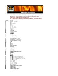
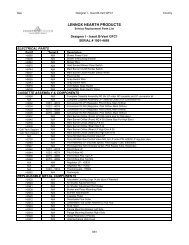
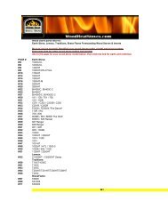
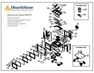
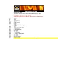
PARTS LISTS<br />
Part # Description Part # Description<br />
2310-020 BRICK PANEL FRONT 5<strong>30</strong>1-050 HEATSHIELD: REAR, RIGHT, CHA/SAN<br />
27X0-655 DOOR HANDLE 5<strong>30</strong>1-060 RESTRICTOR PLATE ASSEMBLY<br />
27X0-650 FRONT DOOR 5<strong>30</strong>1-070 SHUTTE POSITION INDICATOR<br />
2710-600 BOTTOM: SAN 5<strong>30</strong>1-080 OUTLET RESTRICTOR CLIP<br />
2710-810 TOP GRILL 5701-925H STARTER COLLAR<br />
27X0-660 FRONT GRILL 5710-470 STONE CLIP<br />
2310-850 HEAT EXCHANGER BASE 7200-351 ORIFICE: BURNER HOOD, LP, #51 SPUD<br />
2310-860 HEAT EXCHANGER 7211-390 3-WAY PILOT HOOD (W/ CLIP)<br />
2310-240 EXHAUST BAFFLE 7211-009 PILOT GAS TUBE<br />
3<strong>03</strong>0-028 GLASS 17-15/32”X11-9/16”X5MM 7211-310 VALVE (NG)<br />
3110-057 LOW DENSITY DOOR ROPE 3/8" 7211-370 PILOT ASSEMBLY (NG)<br />
3160-075 HEAT EXCHANGER FLAT ROPE 1/4” 7210-1<strong>03</strong> PIEZO IGNITER<br />
3160-080 GLASS TAPE 3/4" 7211-017 GAS LINE 3/8 DIAMETER<br />
3160-150 FIREBOX/AIR HEAT EXCHANGER GASKET 7211-221 BURNER ASSEMBLY<br />
3160-152 PILOT GASKET 7211-4<strong>30</strong> IGNITER ELECTRODE<br />
3160-157 GASKET 6" 7211-470 THERMOCOUPLE<br />
3160-<strong>30</strong>0 PRIMARY AIR CONTROL GASKET 7211-512 LOG: BOTTOM, LEFT<br />
5<strong>30</strong>0-066 PIEZO BRACKET 7211-513 LOG: BOTTOM, RIGHT<br />
5<strong>30</strong>0-090 SECONDARY AIR PLENUM 7211-514 LOG: TOP, LEFT<br />
5<strong>30</strong>0-112 RESTRICTOR PLATE 7211-515 LOG: TOP, RIGHT<br />
5<strong>30</strong>0-114 RESTRICTOR PLATE ROD 7211-516 LOG: TOP, CENTER<br />
5<strong>30</strong>1-010 FIREBOX: CHA/SAN 7211-517 EMBERS: PYROTEK, 4 OZ.<br />
5<strong>30</strong>1-<strong>03</strong>0 CONTROL: PRIMARY AIR ASSEMBLY<br />
5<strong>30</strong>1-<strong>04</strong>0 HEATSHIELD: REAR, LEFT, CHA/SAN<br />
Accessories available:<br />
BLOWER KIT # (93-57010)<br />
REMOTE CONTROL ON/OFF # (90-56912)<br />
REMOTE CONTROL THERMOSTAT # (90-56914)<br />
• WARNING! Do not substitute Materials.<br />
For replacement parts, or for information about parts or service, contact your authorized Hearthstone<br />
retailer. For the name of the authorized retailer nearest to you, visit our website at<br />
www.Hearthstonestoves.com, or e-mail us at inquiry@Hearthstonestoves.com.<br />
22<br />
07<strong>04</strong>4-2
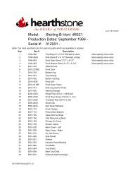
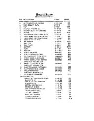
RATING LABEL<br />
23<br />
07<strong>04</strong>4-2
TROUBLESHOOTING GUIDE<br />
Symptom Possible Cause Corrective Action<br />
1. Pilot will not A. Insufficient gas pressure, A. Using the piezo sparker, try to light the pilot. If it will<br />
light.<br />
air in the pilot line, or dirty or not light, check the inlet gas pressure.<br />
kinked gas line.<br />
B. Pilot orifice plugged. B. Clean or replace the pilot assembly.<br />
C. Defective or misaligned<br />
electrode at pilot.<br />
C. If a match lights a pilot, check the electrode gap <strong>and</strong><br />
location. Should be a 1/8" gap in the flame area.<br />
D. Defective igniter. D. Check for a good connection between igniter <strong>and</strong><br />
electrode. Check wire insulation. If properly connected<br />
<strong>and</strong> no spark, replace igniter.<br />
2. Pilot will not stay<br />
lit after carefully<br />
following lighting<br />
instructions.<br />
E. After sitting for "off"<br />
season (summer), pilot<br />
assembly may be dirty.<br />
A. Low or too high gas<br />
pressure<br />
E. Clean or replace the pilot assembly.<br />
A. Check for proper inlet pressure for the gas being<br />
used.<br />
B. Faulty connections. B. Measure voltage between valve body <strong>and</strong> solder<br />
connection on the rear of the valve (where the blue wire<br />
connects). It should be no less than 7 mV.<br />
C. Defective thermocouple. C1. Ensure that the thermocouple connection at the gas<br />
valve is tight.<br />
C2. Check thermocouple output using milli-volt meter.<br />
Disconnect from valve <strong>and</strong> read voltage across wire<br />
ends. If the reading is less than 15 mV, replace the pilot<br />
assembly.<br />
C3. If burning NG, check pilot flame to see that it is<br />
impinging on the top of the thermocouple. Clean or<br />
replace pilot for maximum flame impingement.<br />
D. Pilot dirty or plugged. D. Clean or replace the pilot assembly.<br />
24<br />
07<strong>04</strong>4-2
Symptom Possible Cause Corrective Action<br />
3. Pilot burning, no A. Thermostat switch or<br />
gas to main burner, wires defective.<br />
valve knob in the<br />
"ON" position,<br />
thermostat <strong>and</strong>/or<br />
on/off/t'stat switch<br />
A. Check thermostat/wiring for proper connections.<br />
Place jumper wire across terminals at thermostat. If<br />
burner comes on, replace defective thermostat. If not<br />
OK, place jumper across thermostat wires at gas valve.<br />
If burner comes on, tighten connections, or replace<br />
faulty wires.<br />
in the "ON"<br />
position.<br />
B. Thermopile may not be B. Check thermopile output, using a milli-volt meter. If<br />
generating sufficient voltage. the optional on/off kit has not been installed, take the<br />
readings across generator terminals of the gas valve.<br />
TPTH <strong>and</strong> TP). With the on/off kit, take the readings<br />
across TH <strong>and</strong> Terminal block (which corresponds to #3<br />
on the switch). Milli-volt reading should be greater than<br />
325 mV. If not, replace the pilot assembly. If the meter<br />
reading is OK, but the burner does not come on, replace<br />
the gas valve.<br />
C. Plugged burner orifice. C. Remove <strong>and</strong> check burner orifice, clean or replace.<br />
Note: do not use any metal cleaning device, as this may<br />
damage the orifice.<br />
4. Pilot <strong>and</strong> burner<br />
come on, but go<br />
out after some<br />
warm-up.<br />
A. Inconsistent, of<br />
insufficient flame on<br />
thermopile.<br />
A. Adjust pilot flame size <strong>and</strong> assure that the flame is<br />
aimed directly at the thermopile.<br />
B. Insufficient gas pressure. B. Check line pressure to ensure that the correct inlet<br />
pressure is present for the type of gas being used. If<br />
propane pressure is inconsistent, check for water<br />
condensation at the regulator.<br />
5. Frequent pilot<br />
outage problem.<br />
A. Pilot flame may be too<br />
low or blowing, (high),<br />
causing the pilot safety to<br />
drop out.<br />
6. Glass fogs A. A normal result of gas<br />
combustion.<br />
A. Clean <strong>and</strong>/or adjust the pilot flame for maximum<br />
impingement on the thermopile <strong>and</strong> thermocouple.<br />
A. After the heater has warmed up, the glass should<br />
clear.<br />
7. Blue Flames A. A normal result during the A. Flames should begin to turn more yellowish after 20<br />
first 20 minutes.<br />
minutes of burning.<br />
B. If the blue color stays; adjust the air shutter for a<br />
proper burn.<br />
25<br />
07<strong>04</strong>4-2
Symptom Possible Cause Corrective Action<br />
8. Floating flames, A. Potentially dangerous<br />
lazy ill-defined, incomplete combustion due<br />
quiet flames, which to incorrect air to fuel ratio<br />
roll around, (lack of combustion air or<br />
sometimes excessive fuel delivery I.e.<br />
completely off of excessive gas pressure,<br />
the port,<br />
overrating of appliance).<br />
sometimes with B. Incorrect air<br />
overly, yellow tips. intake/exhaust flow system.<br />
Possible sooting. Causes may be:<br />
Usually<br />
B1. Blocked burner.<br />
accompanied by B2. Blocked primary air<br />
the odor of B3. Blocked secondary air<br />
aldehydes. inlets<br />
A. Check the appliance input rate <strong>and</strong> reduce if<br />
necessary. The air intake/exhaust flow system may be<br />
too restrictive or blocked (the rate at which the exhaust<br />
leaves [draft] determines the rate at which the<br />
combustion air is delivered). Poor draft results in<br />
insufficient air delivery or a restricted exhaust. Correct<br />
air intake/exhaust flow system.<br />
B1. Clear ports.<br />
B2. Clear obstructions.<br />
B3. Clear obstructions.<br />
C. If gas pressures are correct <strong>and</strong> the flames stay the<br />
same, adjust the air shutter for a proper burn.<br />
9. Burner<br />
flashback. Air-gas<br />
mixture ignites<br />
inside the burner<br />
near the orifice,<br />
usually creating a<br />
roaring noise like a<br />
blowtorch. The<br />
problem is an<br />
imbalance of gas<br />
flow velocity <strong>and</strong><br />
burning speed<br />
pattern.<br />
A. Excessive.<br />
B. Burner input underrated.<br />
C. Valve leak if flashback<br />
occurs with burner valve in<br />
off position.<br />
D. Improper gas pipe size.<br />
A. Adjust the air shutter for a proper burn.<br />
B. Check input rate. Check input pressure using a<br />
manometer. Confirm correct gas pressure at house<br />
meter or tank (call gas company). Confirm burner orifice<br />
size.<br />
C. Replace valve. If above corrections do not eliminate<br />
flashback, replace burner.<br />
D. Correct plumbing.<br />
10. Delayed A. Incorrect air-to-fuel ratio.<br />
ignition (makes a A1. Primary air incorrect.<br />
sudden "whoosh" A2. Burner ports plugged.<br />
noise as the burner B. Improper log placement.<br />
lights). This is a<br />
buildup of gas prior<br />
to ignition. This is<br />
more prevalent with<br />
propane (LP) fuel.<br />
A1. Adjust the air shutter for a proper burn.<br />
A2. Open ports to allow for proper travel of flames.<br />
B. Reposition logs to eliminate interference with flame<br />
travel.<br />
26<br />
07<strong>04</strong>4-2
HEARTHSTONE GAS-FIRED STOVE AND INSERT<br />
LIMITED WARRANTIES<br />
These warranties give you specific legal rights. You may also have other rights that vary from State to<br />
State.<br />
Hearthstone Quality Home <strong>Heat</strong>ing Products, Inc. (Hearthstone) warrants to the original purchaser only<br />
(the “Original Purchaser”) the new gas-fired stove/insert manufactured by Hearthstone <strong>and</strong> purchased by<br />
the Original Purchaser (referred to as the “Stove” for simplicity) against any of the occurrences listed in<br />
this document that result from defects in material or workmanship. All obligations of Hearthstone under<br />
this document commence on the date the Original Purchaser purchases the Stove (the “Purchase Date”).<br />
LIMITED LIFETIME WARRANTY<br />
Hearthstone warrants the following parts of the Stove against the following occurrences that result from<br />
defects in material <strong>and</strong> workmanship:<br />
• All cast iron parts, including the cast iron heat exchanger – against breakage, cracking or burnthrough.<br />
• All stones – against cracking or breakage due to thermal stress, excluding surface <strong>and</strong> hairline cracks<br />
<strong>and</strong> scratches that do not affect the operation or safety of the Stove.<br />
• Glass – against breakage due to thermal shock.<br />
LIMITED FIVE-YEAR WARRANTY<br />
Hearthstone warrants the following parts of the Stove against the following occurrences that result from<br />
defects in material <strong>and</strong> workmanship:<br />
• Firebox <strong>and</strong> firebox baffle – against breakage, cracking or burn-through.<br />
• Convective heat exchanger – against breakage, cracking or burn-through.<br />
• Burners, air shutters <strong>and</strong> orifices – against breakage, cracking or burn-through.<br />
• Ceramic logs <strong>and</strong> embers – against breakage, cracking or burn-through.<br />
This warranty expires on the fifth (5 th ) anniversary of the Purchase Date.<br />
LIMITED THREE-YEAR WARRANTY<br />
Hearthstone warrants the following parts of the Stove against the following occurrences that result from<br />
defects in material <strong>and</strong> workmanship:<br />
• Gas train, including gas valve, millivolt wiring, spill switch, pilot assembly, thermopile,<br />
thermocouple, piezo igniter, <strong>and</strong>, if the Stove is a vent-free model, ODS system – against breakage or<br />
malfunction.<br />
This warranty expires on the third (3 rd ) anniversary of the Purchase Date.<br />
LIMITED ONE-YEAR WARRANTY<br />
Hearthstone warrants the following parts of the Stove against the following occurrences that result from<br />
defects in material <strong>and</strong> workmanship:<br />
• Enamel Finish – against peeling or fading, excluding chipping, mechanical abrasion, chemical<br />
abrasion or crazing.<br />
• Gaskets <strong>and</strong> sealants – against breakage or deterioration.<br />
• Accessories <strong>and</strong> electrical components such as blowers, switches <strong>and</strong> thermo discs, excluding venting<br />
components, hearth components, electrical components <strong>and</strong> other components or accessories used in<br />
conjunction with the installation of the Stove not manufactured, or supplied by Hearthstone – against<br />
breakage or malfunction.<br />
This warranty expires on the first (1 st ) anniversary of the Purchase Date.<br />
EXCLUSIONS<br />
27<br />
07<strong>04</strong>4-2
The warranties contained in this document do not cover, nor is Hearthstone responsible for:<br />
1. Damage resulting from installation or operation of the Stove in a manner contrary to the owner’s<br />
manual.<br />
2. Damage or non-performance resulting from faulty or incomplete setup, installation <strong>and</strong> start-up or<br />
mish<strong>and</strong>ling, abuse, or misuse of the Stove, including but not limited to over-firing.<br />
3. Damage resulting from installation, modification, alteration, repair or service of the Stove by any<br />
party other than Hearthstone or an authorized Hearthstone dealer (a “Dealer”).<br />
4. Damage due to water or due to installation of the Stove in a damp or high condensation area.<br />
5. Damage due to installation of the Stove in an atmosphere contaminated by damaging chemicals,<br />
including but not limited to chlorine, fluorine or salts.<br />
6. Scratches on glass, enameled surfaces or stones due to mechanical abrasion.<br />
7. St<strong>and</strong>ard wear <strong>and</strong> tear of the Stove resulting from normal usage over time.<br />
8. Damage, operational-related problems, or inadequate performance caused by site, installation or<br />
environmental conditions beyond Hearthstone’s control, including but not limited to nearby trees,<br />
rooftops, buildings, wind, hills, mountains, inadequate or excessive venting, insufficient make up<br />
air, or negative air pressure whether or not caused by mechanical systems such as furnaces,<br />
exhaust fans, clothes dryers, etc.<br />
9. A defect in any part of the Stove if the Original Purchaser fails to comply with Hearthstone’s or a<br />
Dealer’s request to ship the part or the Stove to Hearthstone or a Dealer, as the case may be.<br />
THE WARRANTIES CONTAINED IN THIS DOCUMENT ARE EXCLUSIVE AND ARE GIVEN BY<br />
HEARTHSTONE AND ACCEPTED BY THE ORIGINAL PURCHASER IN LIEU OF ALL OTHER<br />
EXPRESS WARRANTIES AND ANY OBLIGATIONS, LIABILITIES, RIGHTS, CLAIMS, OR<br />
REMEDIES IN CONTRACT OR TORT, WHETHER OR NOT ARISING FROM HEARTHSTONE’S<br />
NEGLIGENCE, ACTUAL OR IMPUTED. ALL IMPLIED WARRANTIES, INCLUDING THE<br />
WARRANTIES OF MERCHANTABILITY AND FITNESS FOR A PARTICULAR PURPOSE, ARE<br />
GIVEN ONLY TO THE EXTENT REQUIRED BY FEDERAL OR STATE LAW. EXCEPT AS<br />
OTHERWISE REQUIRED BY STATE LAW, UPON THE EXPIRATION OF THE EXPRESS<br />
LIMITED WARRANTIES CONTAINED HEREIN, NO IMPLIED WARRANTIES, INCLUDING THE<br />
IMPLIED WARRANTIES OF MERCHANTABILITY OR FITNESS FOR A PARTICULAR<br />
PURPOSE, SHALL APPLY TO THE SUBJECT STOVE. SOME STATES DO NOT ALLOW<br />
LIMITATIONS ON HOW LONG AN IMPLIED WARRANTY LASTS, SO THE ABOVE<br />
LIMITATION MAY NOT APPLY TO YOU.<br />
THE WARRANTIES CONTAINED IN THIS DOCUMENT EXTEND ONLY TO THE ORIGINAL<br />
PURCHASER OF THE STOVE WARRANTED HEREUNDER. THEY DO NOT EXTEND TO ANY<br />
SUBSEQUENT OWNERS.<br />
UNDER NO CIRCUMSTANCES SHALL HEARTHSTONE BE LIABLE TO THE ORIGINAL<br />
PURCHASER, OR ANY OTHER PERSON, FOR ANY INCIDENTAL OR CONSEQUENTIAL<br />
DAMAGES, INCLUDING BUT NOT LIMITED TO DAMAGE TO PROPERTY OR PERSONAL<br />
INJURIES, WHETHER ARISING OUT OF BREACH OF WARRANTY, TORT, OR OTHERWISE,<br />
EVEN IF HEARTHSTONE HAS BEEN APPRAISED OF THE POSSIBILITY OF SUCH DAMAGES.<br />
SOME STATES DO NOT ALLOW THE EXCLUSION OR LIMITATION OF INCIDENTAL OR<br />
CONSEQUENTIAL DAMAGES, SO THE ABOVE LIMITATION OR EXCLUSION MAY NOT<br />
APPLY TO YOU.<br />
28<br />
07<strong>04</strong>4-2
QUALIFYING FOR WARRANTY COVERAGE<br />
To obtain performance of any obligation under this document, the Original Purchaser must, within the<br />
applicable warranty time period, contact Hearthstone, at the address listed in the Warranty Registration<br />
section below, or a Dealer for instructions regarding the return of defective parts for repair, the return of<br />
the stove for repair, or a Dealer service call. The Original Purchaser should refer to the Dealer network<br />
search engine contained on Hearthstone’s Web site (www.Hearthstonestoves.com), to find a Dealer<br />
nearest the Original Purchaser’s location.<br />
REMEDY The remedy for any breach of the foregoing warranties will consist of repair or replacement,<br />
at Hearthstone’s option, of any covered defect in the Stove. When the Original Purchaser contacts<br />
Hearthstone or a Dealer, Hearthstone or the Dealer, as the case may be, will instruct the Original<br />
Purchaser to either return the defective part, or the entire Stove (if needed), with shipping prepaid, to<br />
Hearthstone, or a Dealer, or allow a Dealer to make a service call at the place where the Stove is located.<br />
In the event the Original Purchaser refuses to allow a Dealer to make a service call, Hearthstone, or a<br />
Dealer, as the case may be, will request that the Original Owner return the defective part, or the entire<br />
Stove (if needed), with shipping prepaid, to Hearthstone or a Dealer. Notwithst<strong>and</strong>ing any other<br />
provision of this document, the Original Purchaser shall pay for any travel fees <strong>and</strong> service charges<br />
related to a Dealer’s service call.<br />
Parts: Hearthstone will replace defective parts covered by the foregoing warranties at no charge.<br />
Labor: Within the first (1 st ) year after the Purchase Date, Hearthstone will pay for warranty labor<br />
performed by a Dealer at Hearthstone’s published labor rates in effect at the time the labor is performed.<br />
Thereafter, the Original Purchaser is responsible for the cost of labor.<br />
Shipping cost for parts: Within the first ninety (90) days after the Purchase Date, Hearthstone will pay<br />
for the shipping of Stove parts covered by any of the foregoing warranties to <strong>and</strong> from Hearthstone or a<br />
Dealer, as the case may be. Thereafter, the Original Purchaser is responsible for all shipping costs related<br />
to shipping Stove parts to <strong>and</strong> from Hearthstone or a Dealer, as the case may be.<br />
Shipping cost for the Stove: Within the first (1 st ) year after the Purchase Date, if the Original Purchaser<br />
is instructed to return the Stove to Hearthstone or a Dealer for repair, Hearthstone will pay fifty percent<br />
(50%) <strong>and</strong> the Original Purchaser will pay fifty percent (50%) of the shipping costs related to shipping the<br />
Stove to <strong>and</strong> from Hearthstone or a Dealer, as the case may be. Thereafter, the Original Purchaser is<br />
responsible for one hundred percent (100%) of all of the shipping costs related to shipping the Stove to<br />
<strong>and</strong> from Hearthstone or a Dealer, as the case may be. Notwithst<strong>and</strong>ing any other provision of this<br />
document, in no event will Hearthstone pay for any Dealer fees or other fees for pick up or delivery of the<br />
Stove returned for repair; the Original Purchaser will be responsible for any such fees.<br />
WARRANTY REGISTRATION<br />
The Original Purchaser may send a completed <strong>and</strong> signed Warranty Registration Form, which is enclosed<br />
in the Stove warranty packet, to the following address:<br />
Hearthstone Quality Home <strong>Heat</strong>ing Products, Inc.<br />
Warranty Department<br />
317 Stafford Avenue<br />
Morrisville, VT 05661-8695<br />
NOTE: SENDING IN THE SIGNED WARRANTY REGISTRATION FORM IS NOT A<br />
CONDITION OF WARRANTY COVERAGE OR, HEARTHSTONE’S PERFORMANCE.<br />
29<br />
07<strong>04</strong>4-2