Faster, Better, Cheaper Vibration Testing With Electrodynamic Shakers
Faster, Better, Cheaper Vibration Testing With Electrodynamic Shakers
Faster, Better, Cheaper Vibration Testing With Electrodynamic Shakers

Create successful ePaper yourself
Turn your PDF publications into a flip-book with our unique Google optimized e-Paper software.
<strong>Faster</strong>, <strong>Better</strong>, <strong>Cheaper</strong> <strong>Vibration</strong> <strong>Testing</strong> <strong>With</strong> <strong>Electrodynamic</strong> <strong>Shakers</strong><br />
By Wayne Tustin<br />
Equipment<br />
Reliability Institute<br />
Santa Barbara, California<br />
MECHANICAL SHAKERS<br />
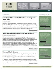
At one time, 1950 and earlier, the only shakers available were mechanical. Some, as in Figure 1, are still in use<br />
for simulating transportation. One axis, vertical, is usually considered sufficient. A typical top frequency<br />
is 60<br />
Hz. Little instrumentation is involved. Easy movement of a manually-moved 1/16 inch shim<br />
under the package<br />
indicates that the shaker<br />
has thrown the package that far into the air.<br />
Figure 1 - Mechanical vibrating platform (courtesy LAB)<br />
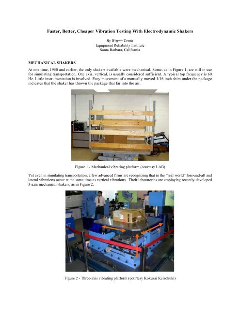
Yet even in<br />
simulating transportation, a few advancedd firms are recognizing that in the “real world” fore-and-aft and<br />
lateral vibrations occur at the same time as vertical vibrations. Their laboratories are employing<br />
recently-developed<br />
3-axis mechanical shakers, as in Figure<br />
2.<br />
Figure 2 - Three-axis vibrating<br />
platform (courtesy Kokusaii Keisokuki)
ELECTROHYDRAULIC (SERVOHYDRAULIC)<br />
SHAKERS<br />
Electrohydraulic (EH) shakers are used in many seismic and landd vehicle applications, up to<br />
500 Hz. Figure 3<br />
shows a typical single-axis system thatt can only deliver last-century sequential-axis (X, then Y, then Z, threee tests)<br />
testing. At<br />
left is the hydraulic supply. At right is the<br />
controller.<br />
Figure 3 - Servohydraulic vibration system<br />
(courtesy Lansmont)<br />
Figure 4 shows EH shaker-driven NEBS (Network Equipment<br />
seismic testing (three tests required).<br />
Building Systems) last-century sequential-axis<br />
Figure 4 - Horizontal NEBS<br />
testing (courtesy Dayton T. . Brown)<br />
Figures 5, 6 and 7 illustrate much newer simultaneous multiaxis testing, faster (one test instead<br />
of three) and<br />
much<br />
more realistic. North-south earth motions differ from east-west earth motions which differ from up-down<br />
earth<br />
motions.
Figure 5 - Seismic investigation of residence (courtesyy Mitsubishi Heavy Industriess LTD.)<br />
Figure 6 - Earthquake simulation (courtesy ANCO Engineers)<br />
Figure 7 - Earthquake simulation (courtesy ASTRO NUCLEARR DYNAMICS, Inc. and ANCO Engineers)
Multiaxis shaking of a nuclear power plant controller, as in Figure 7, is intended to uncover any controller<br />
weaknesses that would lead to failure during a real<br />
earthquake. That controller will be needed if the reactor is<br />
damaged and must be shut down.<br />
Figure 8 shows an excitation platform<br />
driven by multiple EH shakers; for realism, motion must be simultaneous<br />
multiaxis.<br />
Rail transport damage once led to many new vehicles arriving at California dealers with batteries fully discharged.<br />
Why To find out, an observer traveled with the next shipment. Mile after mile, the horns on all those automobiles<br />
were blowing. On a setup like Figure<br />
8, the right laboratory combination of vibration frequency and force led to<br />
horn blowing. Investigation showed a resonance in the horn relayy attachment bracket. Bracket redesign fixed the<br />
problem, as was proved by further shake testing.<br />
Figure 8 - Platform simulatess rail or other transport (courtesy MTS)<br />
Figure 9 illustrates multiple EH shakers simulating road inputs not to platforms but rather into automobile axles via<br />
force-sensing wheels.<br />
Figure 9 - Road simulation on automobile (courtesy MTS)
ELECTRODYNAMIC<br />
SHAKERS<br />
<strong>Electrodynamic</strong> (ED) shakers typically permit last-century single-axis-at-a-time vibration testing to 2,000 Hz.<br />
Figures 10<br />
and 11 show one aspect of<br />
typical ED shaker construction, their suspensions: the spring-like elements<br />
that support shaker armature + test load<br />
+ load attachment fixture. These elements also guide the armature along its<br />
single axis.<br />
Figure 10 - <strong>Electrodynamic</strong> shaker armature and suspension (courtesy<br />
Dynamic Solutions)<br />
Figure 11 - <strong>Electrodynamic</strong> shaker armature and suspension (courtesy Ling Electronics)
“TILT” FIXTURING STILL SINGLE AXIS<br />
Figures 12, 13 and 14 illustrate a misleading attempt to achieve simultaneous multiaxis testing through tilting either<br />
the device under test (DUT) or the shaker. The motion, obviously, is still single axis.<br />
Figure 12 - Tilted fixture does nott multiaxis testt<br />
Figure 13 - Some labs tilt their test articles (courtesy Hong Liu)
Figure 14 - Tilted single-axis shaker maintains normal gravity loading of the test article (Courtesy Quanta Labs)<br />
PNEUMATIC RS OR REPETITIVE<br />
E SHOCK<br />
Figures 15, 16 and 17 illustrate pneumatic RS or Repetitive Shock hammers driving a platform that also functions as<br />
the bottom<br />
of a thermal test chamber.<br />
This is the least expensive way to get simultaneous multiaxis excitation.<br />
Unfortunately, little control is possible over the spectral content of the excitation. An afternoon’s repeat of a<br />
morning test will differ markedly.<br />
Figure<br />
15 - RS actuators combined<br />
with thermal chamber (courtesy QualMark)
Figure 16 - Pneumatic RS units excite the softly-sprung platform<br />
(courtesy GHI)<br />
Figure 17 - Pneumatic RS actuators excite relatively rigid table. Observe the thermal barrier which protects the RS<br />
units from thermal extremes. (courtesy QualMark)<br />
SIMULTANEOUS MULTIAXIS ED<br />
SHAKING<br />
Thus far, no US firm has<br />
offered a three ED shaker array similar too the imported array shown in<br />
Figures 18, 19, 20.<br />
Why not Probably because US military and commercial purchasers of reliablee electronic and other hardware do<br />
not yet understand the benefits of requiring simultaneous multiaxis shaking. It is now permitted by Test Method<br />
527 of MIL-STD-810G.<br />
It should be required.
Figure 18 - Tri-axial automotive electronics shaking, common in Japan, slightly<br />
recognized in<br />
the US (courtesy<br />
IMV, Visteon and Spectrum Technologies)<br />
Figure 19 - Triaxial shaking of automobile headlampss (courtesy Spectrum Technologies)
Figure 21 - IMV calls this motion-combining unit their ICCU (courtesy IMV)<br />
Figure 20<br />
- Three single-axis shakers multi-axis drive a common load (courtesy IMV)<br />
Figure 21 shows IMV’s method of avoiding damage (to the individual ED shaker units) that would be caused by the<br />
other two ED shakers.
Video clip 6 shows 45 o horizontal motion possible with equal in-phase sine excitation of the two<br />
horizontal shakers.<br />
Video clip 7 shows circular flat motion<br />
possible with equal out-of-phase excitation<br />
with the two<br />
shakers. I wish we<br />
could show<br />
you these video clips here. The reader can visualize a third axis excitation with the vertical shaker in<br />
each case: diagonal resultant in Video Clip 6 and spherical resultant in Video Clip 7. The reader can also visualize<br />
possible failures in his own hardware (from 3D excitation) not discoverable by<br />
single-axis-at-a-time last-century<br />
excitation.<br />
Another three-shaker overseas offering is shown in Figure 22.<br />
Figure<br />
22 - Three Chinese shakers (Courtesy Dong Ling & Spectral Dynamics)<br />
FASTER, BETTER, CHEAPER VIBRATION TESTING<br />
<strong>Faster</strong> Certainly. One test instead of three.<br />
<strong>Better</strong> Yes. There has been documentation of weaknesses not found by X then Y then Z testing but found by X +<br />
Y + Z testing.<br />
<strong>Cheaper</strong> Yes. Consider<br />
the time savings of one test instead of three. Consider the design, fabrication, physical<br />
evaluation and storage of<br />
one fixture instead of three. Consider failure avoidance in the field.<br />
ASSEMBLE THREE EXISTING ED<br />
SHAKERS<br />
Granted that purchase of<br />
three shakers + three power amplifiers willl seem expensive. This author remembers selling<br />
their first ED shaker to numerous firms<br />
and agencies 1954-1961 (before he became a teacher). Many of those<br />
firms<br />
and agencies found so many vibration-induced shakers.<br />
The author predicts that simultaneous multiaxis shaking<br />
will quickly “catch<br />
weaknesses in theirr hardware, using that one over-busy shaker, that<br />
they quickly bought additional<br />
on” in the US as it appears to have done<br />
in Asia.<br />
But suppose that we happen to have (or can cheaply<br />
obtain) threee conventionall single-axis shakers. Can we put<br />
them together, as did the US Army, Air<br />
Force and Navy Let’s see how they did it.
The Army Research Lab<br />
at Adelphi, Maryland had a problem. A piece of equipment was failing in service but the<br />
lab, using one shaker, one axis at a time, could not replicate the failure. Somehow ARL got<br />
funding to add two<br />
more shakers, as in Figure 23. That and several other “mysterious”” failures could now be replicated. Simultaneous<br />
shaking at the Army’s White Sands Proving Ground, Figure 24, followed.<br />
Figure 23 - Pioneer three-shaker 3DoF realization (courtesy<br />
US Army)<br />
Figure 24 - Three-shaker 3DoF realization (courtesy Team Corporation and White Sands Proving Ground)<br />
The USAF, by contrast, wanted 6DoF and connected<br />
together eight existing ED<br />
shakers, as shown by Figures 25<br />
and 26. Their lab, in Utah, is operated by Boeing.
Figure 25 - USAF Multiaxis ED shakerss (Courtesy U.S.A.F.)<br />
Figure 26 - USAF Multiaxis ED shakerr (Courtesy U.S.A.F.)<br />
In both Figures 24 and 26 we see spherical hydrostatic bearings that protect the individual ED shakers from damage<br />
by the other ED shakers.<br />
In Figure 27 we see threee existing ED shakers assembled for 3D shaking. Figuree 28 shows an earlier proposal that<br />
would have required a pit for the vertical shaker. Instead, Keyport opted to attach the array to an isolated inertia<br />
mass, as seen in Figure 30.
Figure 27 - Three-shaker Navy 3DoF realization (Courtesy NUWC Keyport and Baughn Engineering)<br />
Figure 28 - Proposed installation; not utilized<br />
(Courtesy NUWC Keyport and Baughn Engineering)
Figure 29 – Three shakers are attached to isolated inertia mass (Courtesy NUWC Keyport and Baughn Engineering)<br />
Figure 30 – Explanation of joining<br />
the three shakers (Courtesyy NUWC Keyport and Baughn Engineering)<br />
Common to Figures 23, 27, 28, 29 and 30 is a sliding action that protects the individual ED shakers from damage by<br />
the other ED shakers.
Figure 30 offers additional details of the Keyport installation. Darkk green and light blue parts move in 3 axes. Red<br />
and orange<br />
parts and the<br />
olive green journal bearings<br />
are stationary. All dark blue parts move<br />
along a single<br />
axis.<br />
Figure 30’ s supplier points out that this<br />
“combiner” unit can be usedd with EH shakers.<br />
Figure 31 - Approximate height of new lab floor (Courtesy NUWC Keyport and Baughn Engineering)<br />
<strong>With</strong> the vertical-axis shaker above the<br />
lab floor, a higher personnel floor was needed in 2005,<br />
as suggested by the<br />
broken line<br />
of Figure 32 and by Figure 33, which appeared as in Figure 34 in April 2006 as the front cover of<br />
TEST<br />
Engineering & Management magazine. That issue contained an article describing the Keyport system in<br />
some<br />
detail.<br />
Figure 32 - New lab floor in place (Courtesy Test Engineering Magazine)
Figure 33 - TEST Engineering and Management front cover; www.testmagazine.biz.<br />
Figure 34<br />
shows earlierr single shaker vertical single-axis excitationn of fixture and<br />
torpedo. The<br />
torpedo needed to<br />
be supported from above, as when carried by torpedo bomber aircraft. (courtesy NSWC<br />
Keyport)<br />
Readers can envision, above the new<br />
floor, a thermal chamber<br />
Figure 29,<br />
now multi-axis.<br />
that accommodates the fixture and torpedo of<br />
CONCLUSION<br />
I ask that audience members and readers exert some effort in influencing prime contractors and<br />
the MIL services to<br />
require simultaneous multiaxis shaking.