GRUNDFOS ALPHA2 L
GRUNDFOS ALPHA2 L
GRUNDFOS ALPHA2 L

Create successful ePaper yourself
Turn your PDF publications into a flip-book with our unique Google optimized e-Paper software.
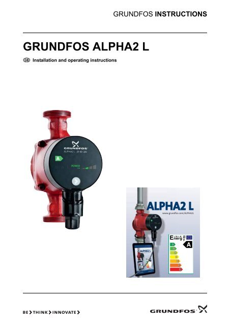
<strong>GRUNDFOS</strong> INSTRUCTIONS<br />
<strong>GRUNDFOS</strong> <strong>ALPHA2</strong> L<br />
Installation and operating instructions<br />
<strong>GRUNDFOS</strong> INSTRUCTIONS<br />
<strong>ALPHA2</strong> L<br />
www.grundfos.com/<strong>ALPHA2</strong>L
Declaration of Conformity<br />
We Grundfos declare under our sole responsibility that the products<br />
<strong>GRUNDFOS</strong> <strong>ALPHA2</strong> L, to which this declaration relates, are in conformity<br />
with the Council Directives on the approximation of the laws of the EC<br />
Member States relating to<br />
— Machinery (98/37/EC).<br />
— Electrical equipment designed for use within certain voltage limits<br />
(2006/95/EC).<br />
Standards used: EN 60335-1: 2002 and EN 60335-2-51: 2003.<br />
— Electromagnetic compatibility (2004/108/EC).<br />
Standards used: EN 61000-6-2 and EN 61000-6-3.<br />
Bjerringbro, 15th May 2008<br />
Svend Aage Kaae<br />
Technical Director<br />
2
CONTENTS<br />
Page<br />
1. Symbols used in this document . . . . . . . . . . . . . . . . . . . . . . . . . . . . . . . . . . . . . . 4<br />
2. General description . . . . . . . . . . . . . . . . . . . . . . . . . . . . . . . . . . . . . . . . . . . . . . . . 5<br />
3. Applications . . . . . . . . . . . . . . . . . . . . . . . . . . . . . . . . . . . . . . . . . . . . . . . . . . . . . . 6<br />
4. Installation . . . . . . . . . . . . . . . . . . . . . . . . . . . . . . . . . . . . . . . . . . . . . . . . . . . . . . . 8<br />
5. Electrical connection . . . . . . . . . . . . . . . . . . . . . . . . . . . . . . . . . . . . . . . . . . . . . . . 11<br />
6. Control panel . . . . . . . . . . . . . . . . . . . . . . . . . . . . . . . . . . . . . . . . . . . . . . . . . . . . . 12<br />
7. Setting the pump . . . . . . . . . . . . . . . . . . . . . . . . . . . . . . . . . . . . . . . . . . . . . . . . . . 14<br />
8. Systems with bypass valve between flow and return pipes . . . . . . . . . . . . . . . . 16<br />
9. Start-up . . . . . . . . . . . . . . . . . . . . . . . . . . . . . . . . . . . . . . . . . . . . . . . . . . . . . . . . . . 18<br />
10. Pump settings and pump performance . . . . . . . . . . . . . . . . . . . . . . . . . . . . . . . . . 20<br />
11. Fault finding chart . . . . . . . . . . . . . . . . . . . . . . . . . . . . . . . . . . . . . . . . . . . . . . . . . 22<br />
12. Technical data and installation dimensions . . . . . . . . . . . . . . . . . . . . . . . . . . . . . 23<br />
13. Performance curves . . . . . . . . . . . . . . . . . . . . . . . . . . . . . . . . . . . . . . . . . . . . . . . . 25<br />
14. Features . . . . . . . . . . . . . . . . . . . . . . . . . . . . . . . . . . . . . . . . . . . . . . . . . . . . . . . . . 31<br />
15. Accessories . . . . . . . . . . . . . . . . . . . . . . . . . . . . . . . . . . . . . . . . . . . . . . . . . . . . . . 33<br />
16. Disposal . . . . . . . . . . . . . . . . . . . . . . . . . . . . . . . . . . . . . . . . . . . . . . . . . . . . . . . . . 34<br />
3
Warning<br />
Prior to installation, read these installation and operating<br />
instructions. Installation and operation must comply with local<br />
regulations and accepted codes of good practice.<br />
1. Symbols used in this document<br />
Warning<br />
If these safety instructions are not observed, it may result in<br />
personal injury!<br />
Caution<br />
Note<br />
If these safety instructions are not observed, it may result in<br />
malfunction or damage to the equipment!<br />
Notes or instructions that make the job easier and ensure safe<br />
operation.<br />
4
2. General description<br />
Contents:<br />
2.1 The <strong>GRUNDFOS</strong> <strong>ALPHA2</strong> L circulator pump<br />
2.2 Advantages of installing a <strong>GRUNDFOS</strong> <strong>ALPHA2</strong> L.<br />
2.1 The <strong>GRUNDFOS</strong> <strong>ALPHA2</strong> L circulator pump<br />
The <strong>GRUNDFOS</strong> <strong>ALPHA2</strong> L circulator pump is designed for the<br />
circulation of water in heating systems.<br />
Install the <strong>GRUNDFOS</strong> <strong>ALPHA2</strong> L in<br />
• underfloor heating systems<br />
• one-pipe systems<br />
• two-pipe systems.<br />
<strong>GRUNDFOS</strong> <strong>ALPHA2</strong> L incorporates a permanent-magnet motor and<br />
differential-pressure control enabling continuous adjustment of the pump<br />
performance to the actual system requirements.<br />
<strong>GRUNDFOS</strong> <strong>ALPHA2</strong> L has a user-friendly front-mounted control panel.<br />
See 6. Control panel and 14. Features.<br />
2.2 Advantages of installing a <strong>GRUNDFOS</strong> <strong>ALPHA2</strong> L<br />
The installation of a <strong>GRUNDFOS</strong> <strong>ALPHA2</strong> L means<br />
easy installation and start-up<br />
• <strong>GRUNDFOS</strong> <strong>ALPHA2</strong> L is easy to install.<br />
With the factory setting, the pump can, in most cases, be started<br />
without making any settings.<br />
high degree of comfort<br />
• Minimum noise from valves, etc.<br />
low energy consumption<br />
• Low energy consumption compared to conventional circulator pumps.<br />
The <strong>GRUNDFOS</strong> <strong>ALPHA2</strong> L is A-labelled.<br />
TM03 0868 0705<br />
Fig. 1<br />
Energy label, A-labelled<br />
5
3. Applications<br />
Contents:<br />
3.1 System types<br />
3.2 Pumped liquids<br />
3.3 System pressure<br />
3.4 Relative air humidity (RH)<br />
3.5 Enclosure class<br />
3.6 Inlet pressure.<br />
3.1 System types<br />
TM04 2521 2608<br />
Fig. 2<br />
Pumped liquids and operating conditions<br />
3.2 Pumped liquids<br />
<strong>GRUNDFOS</strong> <strong>ALPHA2</strong> L is suitable for<br />
• systems with constant or variable flows where it is desirable to<br />
optimise the setting of the pump duty point<br />
• systems with variable flow-pipe temperature.<br />
Clean, thin, non-aggressive and non-explosive liquids, not containing<br />
solid particles, fibres or mineral oil. See fig. 2.<br />
In heating systems, the water should meet the requirements of accepted<br />
standards on water quality in heating systems, e.g. the German standard<br />
VDI 2035.<br />
Warning<br />
The pump must not be used for the transfer of flammable liquids<br />
such as diesel oil, petrol and similar liquids.<br />
6
3.3 System pressure<br />
3.4 Relative air humidity (RH)<br />
3.5 Enclosure class<br />
Maximum 1.0 MPa (10 bar). See fig. 2.<br />
Maximum 95 %. See fig. 2.<br />
IP 42. See fig. 2.<br />
3.6 Inlet pressure<br />
Minimum inlet pressure in relation to liquid temperature. See fig. 2.<br />
Minimum inlet pressure<br />
Liquid temperature<br />
[MPa]<br />
[bar]<br />
≤75 °C 0.005 0.05<br />
90 °C 0.028 0.28<br />
110 °C 0.108 1.08<br />
7
4. Installation<br />
Contents:<br />
4.1 Mounting<br />
4.2 Control box positions<br />
4.3 Changing the control box position<br />
4.4 Insulation of pump housing.<br />
4.1 Mounting<br />
TM04 2522 2608<br />
Fig. 3<br />
Mounting the <strong>GRUNDFOS</strong> <strong>ALPHA2</strong> L<br />
Arrows on the pump housing indicate the liquid flow direction through the<br />
pump.<br />
See 12.2 Installation dimensions – <strong>GRUNDFOS</strong> <strong>ALPHA2</strong> L XX-40, XX-50,<br />
XX-60.<br />
1. Fit the two gaskets supplied when the pump is mounted in the pipe.<br />
See fig. 3, pos. A.<br />
2. Install the pump with the motor shaft horizontal. See fig. 3, pos. B.<br />
8
4.2 Control box positions<br />
A<br />
TM04 2523 2608<br />
Fig. 4<br />
Control box positions<br />
Warning<br />
The pumped liquid may be scalding hot and under high pressure!<br />
Drain the system or close the isolating valves on either side of the<br />
pump before the screws are removed.<br />
Caution<br />
When the position of the control box has been changed, fill the<br />
system with the liquid to be pumped or open the isolating valves.<br />
4.3 Changing the control box position<br />
The control box can be rotated in steps of 90 °.<br />
Possible/permissible positions and the procedure of changing the position<br />
of the control box are illustrated in fig. 4, pos. A.<br />
Procedure:<br />
1. Slacken and remove the four hexagon-socket head screws holding the<br />
pump head with a tee key (M4).<br />
2. Turn the pump head to the desired position.<br />
3. Insert and cross-tighten the screws.<br />
9
4.4 Insulation of pump housing<br />
TM04 2524 2608<br />
Fig. 5<br />
Insulation of pump housing<br />
Note<br />
Limit the heat loss from the pump housing and pipework.<br />
The heat loss from the pump and pipework can be reduced by insulating<br />
the pump housing and the pipe. See fig. 5.<br />
As an alternative, polystyrene insulation shells can be ordered from<br />
Grundfos. See 15. Accessories.<br />
Caution<br />
Do not insulate the control box or cover the control panel.<br />
10
5. Electrical connection<br />
TM04 2525 2608<br />
Fig. 6<br />
Electrical connection<br />
The electrical connections and protection must be carried out in<br />
accordance with local regulations.<br />
Warning<br />
The pump must be connected to earth .<br />
The pump must be connected to an external mains switch with a<br />
minimum contact gap of 3 mm in all poles.<br />
• The motor requires no external motor protection.<br />
• Check that the supply voltage and frequency correspond to the values<br />
stated on the pump. See 14.1 Nameplate.<br />
• Connect the pump to the mains with the plug supplied with the pump<br />
as shown in fig. 6, steps 1 to 8.<br />
• Light in the control panel shows that the electricity supply has been<br />
switched on.<br />
11
6. Control panel<br />
6.1 Elements on the control panel<br />
Contents:<br />
6.1 Elements on the control panel<br />
6.2 "POWER ON" indicator light<br />
6.3 Light fields indicating the pump setting<br />
6.4 Push-button for selection of pump setting.<br />
<strong>ALPHA2</strong> L 25-40 180<br />
1<br />
A<br />
POWER<br />
ON<br />
2<br />
3<br />
TM04 2526 2608<br />
Fig. 7<br />
<strong>GRUNDFOS</strong> <strong>ALPHA2</strong> L control panel<br />
6.2 "POWER ON" indicator light<br />
The control panel on the <strong>GRUNDFOS</strong> <strong>ALPHA2</strong> L comprises:<br />
Pos. Description<br />
1 "POWER ON" indicator light<br />
2 Seven light fields indicating the pump setting<br />
3 Push-button for selection of pump setting<br />
The "POWER ON" indicator light, see fig. 7, pos. 1, is on when the<br />
electricity has been switched on.<br />
When the "POWER ON" indicator light is on only, a fault preventing the<br />
pump from operating properly (e.g. seizing-up) has occurred.<br />
If a fault is indicated, correct the fault and reset the pump by switching the<br />
electricity supply off and on.<br />
12
6.3 Light fields indicating the pump setting<br />
<strong>GRUNDFOS</strong> <strong>ALPHA2</strong> L has seven optional settings which can be<br />
selected with the push-button. See fig. 7, pos. 3.<br />
The pump setting is indicated by seven different light fields. See fig. 8.<br />
POWER<br />
ON<br />
CP1<br />
PP2 CP2<br />
III II I PP1<br />
TM04 2527 2608<br />
Fig. 8<br />
Seven light fields<br />
Button<br />
presses<br />
Light field<br />
See 10. Pump settings and pump performance for information about the<br />
function of the settings.<br />
6.4 Push-button for selection of pump setting<br />
Description<br />
0<br />
PP2<br />
(factory setting)<br />
Highest proportional-pressure curve<br />
1 CP1 Lowest constant-pressure curve<br />
2 CP2 Highest constant-pressure curve<br />
3 III Constant curve, speed III<br />
4 II Constant curve, speed II<br />
5 I Constant curve, speed I<br />
6 PP1 Lowest proportional-pressure curve<br />
7 PP2 Highest proportional-pressure curve<br />
Every time the push-button is pressed, see fig. 7, pos. 3, the pump setting<br />
is changed.<br />
A cycle is seven button presses. See 6.3 Light fields indicating the pump<br />
setting.<br />
13
7. Setting the pump<br />
Contents:<br />
7.1 Pump setting for system type<br />
7.2 Pump control.<br />
7.1 Pump setting for system type<br />
TM04 2528 2608<br />
Fig. 9<br />
Selection of pump setting for system type<br />
Pos.<br />
A<br />
B<br />
System type<br />
Underfloor heating<br />
Two-pipe systems<br />
Factory setting = Highest proportional-pressure curve (PP2).<br />
Recommended and alternative pump settings according to fig. 9:<br />
Recommended<br />
Lowest constant-pressure curve<br />
(CP1)*<br />
Highest proportional-pressure<br />
curve (PP2)*<br />
Lowest proportional-pressure<br />
C One-pipe systems<br />
curve (PP1)*<br />
* See 13.1 Guide to performance curves.<br />
Pump setting<br />
Alternative<br />
Highest constant-pressure curve<br />
(CP2)*<br />
Lowest proportional-pressure<br />
curve (PP1)*<br />
Highest proportional-pressure<br />
curve (PP2)*<br />
Changing from recommended to alternative pump setting<br />
Heating systems are "slow" systems that cannot be set to the optimum<br />
operation within minutes or hours.<br />
If the recommended pump setting does not give the desired distribution of<br />
heat in the rooms of the house, change the pump setting to the shown<br />
alternative.<br />
Explanation to pump settings in relation to performance curves,<br />
see 10. Pump settings and pump performance.<br />
14
7.2 Pump control<br />
During operation, the pump head will be controlled according to the<br />
principle "proportional-pressure control" (PP) or "constant-pressure<br />
control" (CP).<br />
In these control modes, the pump performance and consequently the<br />
power consumption are adjusted according to the heat demand in the<br />
system.<br />
Proportional-pressure control<br />
In this control mode, the differential pressure across the pump is<br />
controlled according to the flow.<br />
The proportional-pressure curves are indicated by PP1 and PP2 in the<br />
Q/H diagrams. See 10. Pump settings and pump performance.<br />
Constant-pressure control<br />
In this control mode, a constant differential pressure across the pump is<br />
maintained, irrespective of the flow.<br />
The constant-pressure curves are indicated by CP1 and CP2 and are<br />
the horizontal performance curves in the Q/H diagrams. See 10. Pump<br />
settings and pump performance.<br />
15
8. Systems with bypass valve between flow and return pipes<br />
8.1 Purpose of bypass valve<br />
Contents:<br />
8.1 Purpose of bypass valve<br />
8.2 Manually operated bypass valve<br />
8.3 Automatic bypass valve (thermostatically controlled).<br />
A<br />
TM04 2529 2608<br />
8.2 Manually operated bypass valve<br />
Fig. 10 Systems with bypass valve<br />
Bypass valve<br />
The purpose of the bypass valve is to ensure that the heat from the boiler<br />
can be distributed when all valves in the underfloor-heating circuits and/or<br />
thermostatic radiator valves are closed.<br />
System elements:<br />
• bypass valve<br />
• flowmeter, pos. A.<br />
The minimum flow must be present when all valves are closed.<br />
The pump setting depends on the type of bypass valve used, i.e. manually<br />
operated or thermostatically controlled.<br />
Follow this procedure:<br />
1. Adjust the bypass valve with the pump in setting I (speed I).<br />
The minimum flow (Q min. ) for the system must always be observed.<br />
Consult the manufacturer's instructions.<br />
2. When the bypass valve has been adjusted, set the pump according to<br />
7. Setting the pump.<br />
16
8.3 Automatic bypass valve (thermostatically controlled)<br />
Follow this procedure:<br />
1. Adjust the bypass valve with the pump in setting I (speed I).<br />
The minimum flow (Q min. ) for the system must always be observed.<br />
Consult the manufacturer's instructions.<br />
2. When the bypass valve has been adjusted, set the pump to the lowest<br />
or highest constant-pressure curve.<br />
Explanation to pump settings in relation to performance curves, see<br />
10. Pump settings and pump performance.<br />
17
9. Start-up<br />
Contents:<br />
9.1 Before start-up<br />
9.2 Venting the pump<br />
9.3 Venting of heating systems.<br />
9.1 Before start-up<br />
9.2 Venting the pump<br />
Do not start the pump until the system has been filled with liquid and<br />
vented. The required minimum inlet pressure must be available at the<br />
pump inlet. See 3. Applications and 12. Technical data and installation<br />
dimensions.<br />
TM04 2530 2608<br />
Fig. 11 Venting the pump<br />
The pump is self-venting. It need not be vented before start-up.<br />
Air in the pump may cause noise. This noise ceases after a few minutes<br />
running.<br />
Quick venting of the pump can be obtained by setting the pump to speed<br />
III for a short period, depending on system size and design.<br />
When the pump has been vented, i.e. when the noise has ceased, set the<br />
pump according to the recommendations. See 7. Setting the pump.<br />
Caution<br />
The pump must not run dry.<br />
The system cannot be vented through the pump. See 9.3 Venting of<br />
heating systems.<br />
18
9.3 Venting of heating systems<br />
TM04 2531 2608<br />
Fig. 12 Venting of heating systems<br />
The heating system can be vented via an air escape valve installed above<br />
the pump (1).<br />
In heating systems that often contain much air, Grundfos recommends the<br />
installation of pumps with pump housing with air separator, i.e. <strong>ALPHA2</strong><br />
pumps, type <strong>ALPHA2</strong> XX-XX A.<br />
When the heating system has been filled with liquid, follow this procedure:<br />
1. Open the air escape valve.<br />
2. Set the pump to speed III.<br />
3. Let the pump run for a short period, depending on system size and<br />
design.<br />
4. When the system has been vented, i.e. when the possible noise has<br />
ceased, set the pump according to the recommendations. See<br />
7. Setting the pump.<br />
Repeat the procedure, if necessary.<br />
Caution<br />
The pump must not run dry.<br />
19
10. Pump settings and pump performance<br />
Contents:<br />
10.1 Relation between pump setting and pump performance.<br />
10.1 Relation between pump setting and pump performance<br />
Figure 13 shows the relation between pump setting and pump<br />
performance by means of curves. See also 13. Performance curves.<br />
POWER<br />
AUTO ON<br />
PP1 CP1 PP2 CP2<br />
H<br />
I<br />
II<br />
III<br />
Q<br />
TM04 2532 2608<br />
Fig. 13 Pump setting in relation to pump performance<br />
Setting Pump curve Function<br />
PP1<br />
PP2<br />
(factory<br />
setting)<br />
CP1<br />
CP2<br />
III<br />
Lowest<br />
proportionalpressure<br />
curve<br />
Highest<br />
proportionalpressure<br />
curve<br />
Lowest<br />
constantpressure<br />
curve<br />
Highest<br />
constantpressure<br />
curve<br />
Speed III<br />
The duty point of the pump will move up or down on the lowest<br />
proportional-pressure curve, see fig. 13, depending on the heating<br />
demand.<br />
The head (pressure) is reduced at falling heating demand and<br />
increased at rising heating demand.<br />
The duty point of the pump will move up or down on the highest<br />
proportional-pressure curve, see fig. 13, depending on the heating<br />
demand.<br />
The head (pressure) is reduced at falling heating demand and<br />
increased at rising heating demand.<br />
The duty point of the pump will move out or in on the lowest<br />
constant-pressure curve, see fig. 13, depending on the heating<br />
demand in the system.<br />
The head (pressure) is kept constant, irrespective of the heating<br />
demand.<br />
The duty point of the pump will move out or in on the highest<br />
constant-pressure curve, see fig. 13, depending on the heating<br />
demand in the system.<br />
The head (pressure) is kept constant, irrespective of the heating<br />
demand.<br />
<strong>ALPHA2</strong> L runs at a constant speed and consequently on a<br />
constant curve.<br />
In speed III, the pump is set to run on the max. curve under all<br />
operating conditions. See fig. 13.<br />
Quick venting of the pump can be obtained by setting the pump to<br />
speed III for a short period. See 9.2 Venting the pump.<br />
20
Setting Pump curve Function<br />
II<br />
I<br />
Speed II<br />
Speed I<br />
<strong>ALPHA2</strong> L runs at a constant speed and consequently on a<br />
constant curve.<br />
In speed II, the pump is set to run on the medium curve under all<br />
operating conditions. See fig. 13.<br />
<strong>ALPHA2</strong> L runs at a constant speed and consequently on a<br />
constant curve.<br />
In speed I, the pump is set to run on the min. curve under all<br />
operating conditions. See fig. 13.<br />
21
11. Fault finding chart<br />
Warning<br />
Before starting any work on the pump, make sure that the electricity<br />
supply has been switched off and that it cannot be accidentally<br />
switched on.<br />
Fault<br />
1. The pump<br />
does not run.<br />
2. Noise in the<br />
system.<br />
3. Noise in the<br />
pump.<br />
4. Insufficient<br />
heat.<br />
Control<br />
panel<br />
Cause<br />
Light off. a) One fuse in the<br />
installation is blown.<br />
b) The current-operated or<br />
voltage-operated circuit<br />
breaker has tripped out.<br />
"POWER<br />
ON" is on<br />
only.<br />
"POWER<br />
"ON" and the<br />
light field for<br />
pump setting<br />
are on.<br />
"POWER<br />
"ON" and the<br />
light field for<br />
pump setting<br />
are on.<br />
"POWER<br />
"ON" and the<br />
light field for<br />
pump setting<br />
are on.<br />
Remedy<br />
Replace the fuse.<br />
Cut in the circuit breaker.<br />
c) The pump is defective. Replace the pump.<br />
a) Electricity supply failure.<br />
Might be too low.<br />
Check that the electricity supply<br />
falls within the specified range.<br />
b) The pump is blocked. Remove the impurities.<br />
a) Air in the system. Vent the system.<br />
See 9.3 Venting of heating<br />
systems.<br />
b) The flow is too high. Reduce the suction head.<br />
See 10. Pump settings and<br />
pump performance.<br />
a) Air in the pump. Let the pump run. It vents itself<br />
over time.<br />
See 9.2 Venting the pump.<br />
b) The inlet pressure is too<br />
low.<br />
a) The pump performance<br />
is too low.<br />
Increase the inlet pressure or<br />
check the air volume in the<br />
expansion tank, if installed.<br />
Increase the suction head.<br />
See 10. Pump settings and<br />
pump performance.<br />
22
12. Technical data and installation dimensions<br />
12.1 Technical data<br />
Contents:<br />
12.1 Technical data<br />
12.2 Installation dimensions – <strong>GRUNDFOS</strong> <strong>ALPHA2</strong> L XX-40, XX-50,<br />
XX-60.<br />
Supply voltage 1 x 230 V – 10 %/+ 6 %, 50 Hz, PE<br />
Motor protection The pump requires no external motor protection.<br />
Enclosure class IP 42<br />
Insulation class F<br />
Relative air humidity Maximum 95 %<br />
System pressure Maximum 1.0 MPa, 10 bar, 102 m head<br />
Inlet pressure Liquid temperature Minimum inlet pressure<br />
≤+75 °C 0.05 bar, 0.005 MPa, 0.5 m head<br />
+90 °C 0.28 bar, 0.028 MPa, 2.8 m head<br />
+110 °C 1.08 bar, 0.108 MPa, 10.8 m head<br />
EMC EN 61000-6-2 and EN 61000-6-3<br />
Sound pressure level The sound pressure level of the pump is lower than 43 dB(A).<br />
Ambient temperature 0 °C to +40 °C<br />
Temperature class TF110 to CEN 335-2-51<br />
Surface temperature The maximum surface temperature will not exceed +125 °C.<br />
Liquid temperature +2 °C to +110 °C<br />
To avoid condensation in the control box and stator, the liquid temperature<br />
must always be higher than the ambient temperature.<br />
Ambient temperature<br />
[°C]<br />
Min.<br />
[°C]<br />
Liquid temperature<br />
Max.<br />
[°C]<br />
0 2 110<br />
10 10 110<br />
20 20 110<br />
30 30 110<br />
35 35 90<br />
40 40 70<br />
23
12.2 Installation dimensions – <strong>GRUNDFOS</strong> <strong>ALPHA2</strong> L XX-40, XX-50, XX-60<br />
TM04 2533 2608<br />
Fig. 14 Dimensional sketches, <strong>ALPHA2</strong> L XX-40, XX-50, XX-60<br />
Pump type<br />
Dimensions<br />
L1 B1 B2 B3 B4 H1 H2 H3 G<br />
<strong>ALPHA2</strong> L 15-40 130 130 77 78 46 49 27 129 79 1<br />
<strong>ALPHA2</strong> L 15-50 130* 130 77 78 46 49 27 129 79 1 1/2<br />
<strong>ALPHA2</strong> L 25-40 130 130 77 78 46 49 27 129 79 1 1/2<br />
<strong>ALPHA2</strong> L 25-40 180 180 78 77 47 48 26 127 81 1 1/2<br />
<strong>ALPHA2</strong> L 32-40 180 180 78 77 47 48 26 127 81 2<br />
<strong>ALPHA2</strong> L 15-60 130 130 77 78 46 49 27 129 79 1**<br />
<strong>ALPHA2</strong> L 25-60 130 130 77 78 46 49 27 129 79 1 1/2<br />
<strong>ALPHA2</strong> L 25-60 180 180 78 77 47 48 26 127 81 1 1/2<br />
<strong>ALPHA2</strong> L 32-60 180 180 78 77 47 48 26 127 81 2<br />
*) For the UK market only. **) For UK 1 1/2.<br />
24
13. Performance curves<br />
Contents:<br />
13.1 Guide to performance curves<br />
13.2 Curve conditions<br />
13.3 Performance curves, <strong>ALPHA2</strong> L XX-40<br />
13.4 Performance curves, <strong>ALPHA2</strong> L XX-50<br />
13.5 Performance curves, <strong>ALPHA2</strong> L XX-60.<br />
25
13.1 Guide to performance curves<br />
Each pump setting has its own performance curve (Q/H curve).<br />
A power curve (P1 curve) belongs to each Q/H curve. The power curve<br />
shows the pump power consumption (P1) in Watt at a given Q/H curve.<br />
The P1 value corresponds to the value that can be read from the pump<br />
display, see fig. 15:<br />
POWER AUTO<br />
ADAPT ON<br />
PP1 PP2<br />
CP1 CP2<br />
H<br />
II<br />
III<br />
I<br />
Q<br />
P1<br />
III<br />
II<br />
I<br />
Fig. 15 Performance curves in relation to pump setting<br />
Q<br />
TM04 2534 2608<br />
Setting<br />
PP1<br />
PP2<br />
(factory setting)<br />
CP1<br />
CP2<br />
III<br />
II<br />
I<br />
Pump curve<br />
Lowest proportional-pressure curve<br />
Highest proportional-pressure curve<br />
Lowest constant-pressure curve<br />
Highest constant-pressure curve<br />
Constant speed, speed III<br />
Constant speed, speed II<br />
Constant speed, speed I<br />
For further information about pump settings, see<br />
6.3 Light fields indicating the pump setting<br />
7. Setting the pump<br />
10. Pump settings and pump performance.<br />
26
13.2 Curve conditions<br />
The guidelines below apply to the curves on the next pages:<br />
• Test liquid: Airless water.<br />
• The curves apply to a density of ρ = 983.2 kg/m 3 and a liquid<br />
temperature of +60 °C.<br />
• All curves show average values and should not be used as guarantee<br />
curves. If a specific minimum performance is required, individual<br />
measurements must be made.<br />
• The curves for speeds I, II and III are marked.<br />
• The curves apply to a kinematic viscosity of υ = 0.474 mm 2 /s<br />
(0.474 cSt).<br />
27
13.3 Performance curves, <strong>ALPHA2</strong> L XX-40<br />
pp<br />
HH<br />
[kP [kPa]<br />
[m] [m]<br />
40 40<br />
4 4<br />
30 30<br />
3 3<br />
20 20<br />
2 2<br />
10 10<br />
0 0<br />
1 1<br />
II II III III<br />
I I<br />
0 0<br />
0.0 0.0 0.2 0.2 0.4 0.4 0.6 0.6 0.8 0.8 1.0 1.0 1.2 1.2 1.4 1.4 1.6 1.6 1.8 1.8 2.0 2.0 2.2 2.2 Q[m³/h] Q 0.0 0.0 0.1 0.1 0.2 0.2 0.3 0.3 0.4 0.4 0.5 0.5 0.6 0.6 Q[l/s] Q [l/s]<br />
P1 P1<br />
[W[W]<br />
]<br />
25 25<br />
III III<br />
20 20<br />
II II<br />
15 15<br />
10 10<br />
5 5<br />
I I<br />
0 0<br />
0.0 0.0 0.2 0.2 0.4 0.4 0.6 0.6 0.8 0.8 1.0 1.0 1.2 1.2 1.4 1.4 1.6 1.6 1.8 1.8 2.0 2.0 2.2 2.2 Q[m³/h] Q TM04 2110 2008<br />
Fig. 16 Performance curves, <strong>ALPHA2</strong> L XX-40<br />
28
13.4 Performance curves, <strong>ALPHA2</strong> L XX-50<br />
p<br />
[kPa]<br />
50<br />
40<br />
30<br />
20<br />
10<br />
0<br />
H<br />
[m]<br />
5<br />
4<br />
3<br />
2<br />
1<br />
0<br />
0.0 0.2 0.4 0.6 0.8 1.0 1.2 1.4 1.6 1.8 2.0 2.2 2.4 2.6 Q [m³/h]<br />
I<br />
II<br />
III<br />
P1<br />
[W]<br />
35<br />
30<br />
25<br />
20<br />
15<br />
10<br />
5<br />
0<br />
0.0 0.1 0.2 0.3 0.4 0.5 0.6 0.7 Q [l/s]<br />
0.0 0.2 0.4 0.6 0.8 1.0 1.2 1.4 1.6 1.8 2.0 2.2 2.4 2.6 Q [m³/h]<br />
I<br />
II<br />
III<br />
TM04 2109 2008<br />
Fig. 17 Performance curves, <strong>ALPHA2</strong> L XX-50<br />
29
13.5 Performance curves, <strong>ALPHA2</strong> L XX-60<br />
p<br />
[kPa]<br />
60<br />
50<br />
40<br />
30<br />
20<br />
10<br />
0<br />
H<br />
[m]<br />
6<br />
5<br />
4<br />
3<br />
2<br />
1<br />
0<br />
0.0 0.2 0.4 0.6 0.8 1.0 1.2 1.4 1.6 1.8 2.0 2.2 2.4 2.6 2.8Q [m³/h]<br />
I<br />
II<br />
III<br />
P1<br />
[W]<br />
50<br />
40<br />
30<br />
20<br />
0.0 0.1 0.2 0.3 0.4 0.5 0.6 0.7 0.8 Q [l/s]<br />
II<br />
III<br />
10<br />
I<br />
0<br />
0.0 0.2 0.4 0.6 0.8 1.0 1.2 1.4 1.6 1.8 2.0 2.2 2.4 2.6 2.8Q [m³/h]<br />
TM04 2108 2008<br />
Fig. 18 Performance curves, <strong>ALPHA2</strong> L XX-60<br />
30
14. Features<br />
Contents:<br />
14.1 Nameplate<br />
14.2 Type key.<br />
14.1 Nameplate<br />
1<br />
<strong>ALPHA2</strong> L 25-40 180<br />
<strong>ALPHA2</strong>L 25-40 180<br />
A<br />
POWER AUTO<br />
ADAPT ON<br />
W<br />
2<br />
3<br />
4<br />
5<br />
6<br />
7<br />
Prod. No. 95047562<br />
11/1(A) P1(W) MPa<br />
Serial No. 00000001 Min. 0.05 5<br />
PC 0833 TF110 Max. 0.19 22 1.0<br />
IP 42 230V ~ 50Hz MADE IN DENMARK<br />
8<br />
9<br />
10<br />
11<br />
12<br />
13<br />
TM04 2535 2608<br />
Fig. 19 Nameplate, <strong>GRUNDFOS</strong> <strong>ALPHA2</strong> L<br />
Pos. Description Pos. Description<br />
1 Pump type 8<br />
Rated current [A]:<br />
• Min.: Minimum current [A]<br />
• Max.: Maximum current [A]<br />
2 Product number 9<br />
Input power P 1 [W]:<br />
• Min.: Minimum input power P 1 [W]<br />
• Max.: Maximum input power P 1 [W]<br />
3 Serial number 10 Maximum system pressure [MPa]<br />
4<br />
Production code<br />
• 1st and 2nd figures = year<br />
11 CE mark and approvals<br />
• 3rd and 4th figures = week<br />
5 Enclosure class 12 Country of origin<br />
6 Voltage [V] 13 Temperature class<br />
7 Frequency [Hz]<br />
31
14.2 Type key<br />
Example <strong>ALPHA2</strong> L 25 -40 180<br />
Pump type<br />
Nominal diameter (DN) of suction and discharge ports [mm]<br />
Maximum head [dm]<br />
Port-to-port length [mm]<br />
32
15. Accessories<br />
TM04 2536 2608<br />
Fig. 20 Accessories<br />
Accessories for <strong>GRUNDFOS</strong> <strong>ALPHA2</strong> L. See fig. 20.<br />
Accessories include<br />
• fittings (unions and valves)<br />
• insulation kits (insulation shells)<br />
• plug.<br />
33
16. Disposal<br />
This product or parts of it must be disposed of in an environmentally<br />
sound way:<br />
1. Use the public or private waste collection service.<br />
2. If this is not possible, contact the nearest Grundfos company or<br />
service workshop.<br />
Subject to alterations.<br />
34
Argentina<br />
Bombas <strong>GRUNDFOS</strong> de Argentina S.A.<br />
Ruta Panamericana km. 37.500 Lote<br />
34A<br />
1619 - Garin<br />
Pcia. de Buenos Aires<br />
Phone: +54-3327 414 444<br />
Telefax: +54-3327 411 111<br />
Australia<br />
<strong>GRUNDFOS</strong> Pumps Pty. Ltd.<br />
P.O. Box 2040<br />
Regency Park<br />
South Australia 5942<br />
Phone: +61-8-8461-4611<br />
Telefax: +61-8-8340 0155<br />
Austria<br />
<strong>GRUNDFOS</strong> Pumpen Vertrieb<br />
Ges.m.b.H.<br />
Grundfosstraße 2<br />
A-5082 Grödig/Salzburg<br />
Tel.: +43-6246-883-0<br />
Telefax: +43-6246-883-30<br />
Belgium<br />
N.V. <strong>GRUNDFOS</strong> Bellux S.A.<br />
Boomsesteenweg 81-83<br />
B-2630 Aartselaar<br />
Tél.: +32-3-870 7300<br />
Télécopie: +32-3-870 7301<br />
Belorussia<br />
Представительство ГРУНДФОС в<br />
Минске<br />
220090 Минск ул.Олешева 14<br />
Телефон: (8632) 62-40-49<br />
Факс: (8632) 62-40-49<br />
Bosnia/Herzegovina<br />
<strong>GRUNDFOS</strong> Sarajevo<br />
Paromlinska br. 16,<br />
BiH-71000 Sarajevo<br />
Phone: +387 33 713290<br />
Telefax: +387 33 231795<br />
Brazil<br />
Mark <strong>GRUNDFOS</strong> Ltda.<br />
Av. Humberto de Alencar Castelo<br />
Branco, 630<br />
CEP 09850 - 300<br />
São Bernardo do Campo - SP<br />
Phone: +55-11 4393 5533<br />
Telefax: +55-11 4343 5015<br />
Bulgaria<br />
<strong>GRUNDFOS</strong> Pumpen Vertrieb<br />
Representative Office - Bulgaria<br />
Bulgaria, 1421 Sofia<br />
Lozenetz District<br />
105-107 Arsenalski blvd.<br />
Phone: +359 2963 3820, 2963 5653<br />
Telefax: +359 2963 1305<br />
Canada<br />
<strong>GRUNDFOS</strong> Canada Inc.<br />
2941 Brighton Road<br />
Oakville, Ontario<br />
L6H 6C9<br />
Phone: +1-905 829 9533<br />
Telefax: +1-905 829 9512<br />
China<br />
<strong>GRUNDFOS</strong> Pumps (Shanghai) Co. Ltd.<br />
51 Floor, Raffles City<br />
No. 268 Xi Zang Road. (M)<br />
Shanghai 200001<br />
PRC<br />
Phone: +86-021-612 252 22<br />
Telefax: +86-021-612 253 33<br />
Croatia<br />
<strong>GRUNDFOS</strong> predstavništvo Zagreb<br />
Cebini 37, Buzin<br />
HR-10000 Zagreb<br />
Phone: +385 1 6595 400<br />
Telefax: +385 1 6595 499<br />
Czech Republic<br />
<strong>GRUNDFOS</strong> s.r.o.<br />
Čajkovského 21<br />
779 00 Olomouc<br />
Phone: +420-585-716 111<br />
Telefax: +420-585-716 299<br />
Denmark<br />
<strong>GRUNDFOS</strong> DK A/S<br />
Martin Bachs Vej 3<br />
DK-8850 Bjerringbro<br />
Tlf.: +45-87 50 50 50<br />
Telefax: +45-87 50 51 51<br />
E-mail: info_GDK@grundfos.com<br />
www.grundfos.com/DK<br />
Estonia<br />
<strong>GRUNDFOS</strong> Pumps Eesti OÜ<br />
Peterburi tee 92G<br />
11415 Tallinn<br />
Tel: + 372 606 1690<br />
Fax: + 372 606 1691<br />
Finland<br />
OY <strong>GRUNDFOS</strong> Pumput AB<br />
Mestarintie 11<br />
FIN-01730 Vantaa<br />
Phone: +358-3066 5650<br />
Telefax: +358-3066 56550<br />
France<br />
Pompes <strong>GRUNDFOS</strong> Distribution S.A.<br />
Parc d’Activités de Chesnes<br />
57, rue de Malacombe<br />
F-38290 St. Quentin Fallavier (Lyon)<br />
Tél.: +33-4 74 82 15 15<br />
Télécopie: +33-4 74 94 10 51<br />
Germany<br />
<strong>GRUNDFOS</strong> GMBH<br />
Schlüterstr. 33<br />
40699 Erkrath<br />
Tel.: +49-(0) 211 929 69-0<br />
Telefax: +49-(0) 211 929 69-3799<br />
e-mail: infoservice@grundfos.de<br />
Service in Deutschland:<br />
e-mail: kundendienst@grundfos.de<br />
Greece<br />
<strong>GRUNDFOS</strong> Hellas A.E.B.E.<br />
20th km. Athinon-Markopoulou Av.<br />
P.O. Box 71<br />
GR-19002 Peania<br />
Phone: +0030-210-66 83 400<br />
Telefax: +0030-210-66 46 273<br />
Hong Kong<br />
<strong>GRUNDFOS</strong> Pumps (Hong Kong) Ltd.<br />
Unit 1, Ground floor<br />
Siu Wai Industrial Centre<br />
29-33 Wing Hong Street &<br />
68 King Lam Street, Cheung Sha Wan<br />
Kowloon<br />
Phone: +852-27861706 / 27861741<br />
Telefax: +852-27858664<br />
Hungary<br />
<strong>GRUNDFOS</strong> Hungária Kft.<br />
Park u. 8<br />
H-2045 Törökbálint,<br />
Phone: +36-23 511 110<br />
Telefax: +36-23 511 111<br />
India<br />
<strong>GRUNDFOS</strong> Pumps India Private Limited<br />
118 Old Mahabalipuram Road<br />
Thoraipakkam<br />
Chennai 600 096<br />
Phone: +91-44 2496 6800<br />
Indonesia<br />
PT <strong>GRUNDFOS</strong> Pompa<br />
Jl. Rawa Sumur III, Blok III / CC-1<br />
Kawasan Industri, Pulogadung<br />
Jakarta 13930<br />
Phone: +62-21-460 6909<br />
Telefax: +62-21-460 6910 / 460 6901<br />
Ireland<br />
<strong>GRUNDFOS</strong> (Ireland) Ltd.<br />
Unit A, Merrywell Business Park<br />
Ballymount Road Lower<br />
Dublin 12<br />
Phone: +353-1-4089 800<br />
Telefax: +353-1-4089 830<br />
Italy<br />
<strong>GRUNDFOS</strong> Pompe Italia S.r.l.<br />
Via Gran Sasso 4<br />
I-20060 Truccazzano (Milano)<br />
Tel.: +39-02-95838112<br />
Telefax: +39-02-95309290 / 95838461<br />
Japan<br />
<strong>GRUNDFOS</strong> Pumps K.K.<br />
Gotanda Metalion Bldg., 5F,<br />
5-21-15, Higashi-gotanda<br />
Shiagawa-ku, Tokyo<br />
141-0022 Japan<br />
Phone: +81 35 448 1391<br />
Telefax: +81 35 448 9619<br />
Korea<br />
<strong>GRUNDFOS</strong> Pumps Korea Ltd.<br />
6th Floor, Aju Building 679-5<br />
Yeoksam-dong, Kangnam-ku, 135-916<br />
Seoul, Korea<br />
Phone: +82-2-5317 600<br />
Telefax: +82-2-5633 725<br />
Latvia<br />
SIA <strong>GRUNDFOS</strong> Pumps Latvia<br />
Deglava biznesa centrs<br />
Augusta Deglava ielā 60, LV-1035, Rīga,<br />
Tālr.: + 371 714 9640, 7 149 641<br />
Fakss: + 371 914 9646<br />
Lithuania<br />
<strong>GRUNDFOS</strong> Pumps UAB<br />
Smolensko g. 6<br />
LT-03201 Vilnius<br />
Tel: + 370 52 395 430<br />
Fax: + 370 52 395 431<br />
Malaysia<br />
<strong>GRUNDFOS</strong> Pumps Sdn. Bhd.<br />
7 Jalan Peguam U1/25<br />
Glenmarie Industrial Park<br />
40150 Shah Alam<br />
Selangor<br />
Phone: +60-3-5569 2922<br />
Telefax: +60-3-5569 2866<br />
México<br />
Bombas <strong>GRUNDFOS</strong> de México S.A. de<br />
C.V.<br />
Boulevard TLC No. 15<br />
Parque Industrial Stiva Aeropuerto<br />
Apodaca, N.L. 66600<br />
Phone: +52-81-8144 4000<br />
Telefax: +52-81-8144 4010<br />
Netherlands<br />
<strong>GRUNDFOS</strong> Netherlands<br />
Veluwezoom 35<br />
1326 AE Almere<br />
Postbus 22015<br />
1302 CA ALMERE<br />
Tel.: +31-88-478 6336<br />
Telefax: +31-88-478 6332<br />
e-mail: info_gnl@grundfos.com<br />
New Zealand<br />
<strong>GRUNDFOS</strong> Pumps NZ Ltd.<br />
17 Beatrice Tinsley Crescent<br />
North Harbour Industrial Estate<br />
Albany, Auckland<br />
Phone: +64-9-415 3240<br />
Telefax: +64-9-415 3250<br />
Norway<br />
<strong>GRUNDFOS</strong> Pumper A/S<br />
Strømsveien 344<br />
Postboks 235, Leirdal<br />
N-1011 Oslo<br />
Tlf.: +47-22 90 47 00<br />
Telefax: +47-22 32 21 50<br />
Poland<br />
<strong>GRUNDFOS</strong> Pompy Sp. z o.o.<br />
ul. Klonowa 23<br />
Baranowo k. Poznania<br />
PL-62-081 Przeźmierowo<br />
Tel: (+48-61) 650 13 00<br />
Fax: (+48-61) 650 13 50<br />
Portugal<br />
Bombas <strong>GRUNDFOS</strong> Portugal, S.A.<br />
Rua Calvet de Magalhães, 241<br />
Apartado 1079<br />
P-2770-153 Paço de Arcos<br />
Tel.: +351-21-440 76 00<br />
Telefax: +351-21-440 76 90<br />
România<br />
<strong>GRUNDFOS</strong> Pompe România SRL<br />
Bd. Biruintei, nr 103<br />
Pantelimon county Ilfov<br />
Phone: +40 21 200 4100<br />
Telefax: +40 21 200 4101<br />
E-mail: romania@grundfos.ro<br />
Russia<br />
ООО Грундфос<br />
Россия, 109544 Москва, ул. Школьная<br />
39<br />
Тел. (+7) 495 737 30 00, 564 88 00<br />
Факс (+7) 495 737 75 36, 564 88 11<br />
E-mail<br />
grundfos.moscow@grundfos.com<br />
Serbia<br />
<strong>GRUNDFOS</strong> Predstavništvo Beograd<br />
Dr. Milutina Ivkovića 2a/29<br />
YU-11000 Beograd<br />
Phone: +381 11 26 47 877 / 11 26 47<br />
496<br />
Telefax: +381 11 26 48 340<br />
Singapore<br />
<strong>GRUNDFOS</strong> (Singapore) Pte. Ltd.<br />
24 Tuas West Road<br />
Jurong Town<br />
Singapore 638381<br />
Phone: +65-6865 1222<br />
Telefax: +65-6861 8402<br />
Slovenia<br />
<strong>GRUNDFOS</strong> PUMPEN VERTRIEB<br />
Ges.m.b.H.,<br />
Podružnica Ljubljana<br />
Blatnica 1, SI-1236 Trzin<br />
Phone: +386 01 568 0610<br />
Telefax: +386 01 568 0619<br />
E-mail: slovenia@grundfos.si<br />
Spain<br />
Bombas <strong>GRUNDFOS</strong> España S.A.<br />
Camino de la Fuentecilla, s/n<br />
E-28110 Algete (Madrid)<br />
Tel.: +34-91-848 8800<br />
Telefax: +34-91-628 0465<br />
Sweden<br />
<strong>GRUNDFOS</strong> AB<br />
Box 333 (Lunnagårdsgatan 6)<br />
431 24 Mölndal<br />
Tel.: +46(0)771-32 23 00<br />
Telefax: +46(0)31-331 94 60<br />
Switzerland<br />
<strong>GRUNDFOS</strong> Pumpen AG<br />
Bruggacherstrasse 10<br />
CH-8117 Fällanden/ZH<br />
Tel.: +41-1-806 8111<br />
Telefax: +41-1-806 8115<br />
Taiwan<br />
<strong>GRUNDFOS</strong> Pumps (Taiwan) Ltd.<br />
7 Floor, 219 Min-Chuan Road<br />
Taichung, Taiwan, R.O.C.<br />
Phone: +886-4-2305 0868<br />
Telefax: +886-4-2305 0878<br />
Thailand<br />
<strong>GRUNDFOS</strong> (Thailand) Ltd.<br />
92 Chaloem Phrakiat Rama 9 Road,<br />
Dokmai, Pravej, Bangkok 10250<br />
Phone: +66-2-725 8999<br />
Telefax: +66-2-725 8998<br />
Turkey<br />
<strong>GRUNDFOS</strong> POMPA San. ve Tic. Ltd.<br />
Sti.<br />
Gebze Organize Sanayi Bölgesi<br />
Ihsan dede Caddesi,<br />
2. yol 200. Sokak No. 204<br />
41490 Gebze/ Kocaeli<br />
Phone: +90 - 262-679 7979<br />
Telefax: +90 - 262-679 7905<br />
E-mail: satis@grundfos.com<br />
Ukraine<br />
ТОВ ГРУНДФОС УКРАЇНА<br />
01010 Київ, Вул. Московська 8б,<br />
Тел.:(+38 044) 390 40 50<br />
Фах.: (+38 044) 390 40 59<br />
E-mail: ukraine@grundfos.com<br />
United Arab Emirates<br />
<strong>GRUNDFOS</strong> Gulf Distribution<br />
P.O. Box 16768<br />
Jebel Ali Free Zone<br />
Dubai<br />
Phone: +971-4- 8815 166<br />
Telefax: +971-4-8815 136<br />
United Kingdom<br />
<strong>GRUNDFOS</strong> Pumps Ltd.<br />
Grovebury Road<br />
Leighton Buzzard/Beds. LU7 8TL<br />
Phone: +44-1525-850000<br />
Telefax: +44-1525-850011<br />
U.S.A.<br />
<strong>GRUNDFOS</strong> Pumps Corporation<br />
17100 West 118th Terrace<br />
Olathe, Kansas 66061<br />
Phone: +1-913-227-3400<br />
Telefax: +1-913-227-3500<br />
Usbekistan<br />
Представительство ГРУНДФОС в<br />
Ташкенте<br />
700000 Ташкент ул.Усмана Носира 1-й<br />
тупик 5<br />
Телефон: (3712) 55-68-15<br />
Факс: (3712) 53-36-35<br />
Addresses revised 09.07.2008
Being responsible is our foundation<br />
Thinking ahead makes it possible<br />
Innovation is the essence<br />
95047490 0908<br />
GB<br />
www.grundfos.com