Installation, Operation & Maintenance ... - American Coolair
Installation, Operation & Maintenance ... - American Coolair
Installation, Operation & Maintenance ... - American Coolair

Create successful ePaper yourself
Turn your PDF publications into a flip-book with our unique Google optimized e-Paper software.
<strong>Installation</strong>, <strong>Operation</strong> &<br />
<strong>Maintenance</strong> Instructions<br />
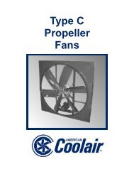
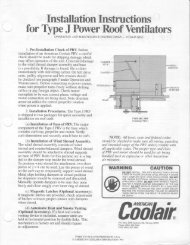
for <strong>Coolair</strong> Propeller Fans<br />
Dimensions of Wall or Other Openings for Mounting Fan. The<br />
<strong>Coolair</strong> fan is designed for all-angle usage and may be mounted in any<br />
position. When face mounted to a wall, the wall opening should be<br />
approximately 3” less than O.D. of the fan frame. If fan frame is to be<br />
recessed into the wall, opening should be 1/4” larger than O.D. of the<br />
fan frame. Shutter installation must be a minimum of 4” from fan blade<br />
exhaust. Shutter must have a net opening equal to or larger than the<br />
diameter of the fan being used. For installation in a wall housing, refer<br />
to the wall housing instructions for recommended wall opening size.<br />
Air Exhaust or Air Supply Usage. The <strong>Coolair</strong> fan is designed<br />
primarily for use as a wall exhaust fan. If supply fan usage is required,<br />
it is recommended that the entire fan unit be mounted in a sheet metal<br />
or plywood sleeve and attached to the wall location with fan position<br />
reversed 180° from the normal wall exhaust position. <strong>Coolair</strong> fans may<br />
be electrically reversed for temporary or emergency use. Fan will not<br />
perform efficiently when electrically reversed.<br />
Pre-<strong>Installation</strong> Check of Fan. Before installation of fan, check<br />
carefully for shipping damage which may result in blade misalignment,<br />
deformed parts or other damage. After motor has been mounted,<br />
check pulley alignment and belt tension. Before connecting the power<br />
source, check motor nameplate to be sure of correct phase and<br />
voltage, and motor voltage connection when motor is dual voltage.<br />
Single phase motors are shipped from factory wired for 230 volt. For<br />
low voltage operation see motor manufacturer’s instructions on<br />
nameplate. Make sure propeller turns freely without striking fan frame<br />
or any foreign object which may interfere with its operation. Note<br />
direction arrow on orifice to make sure propeller is rotating in the<br />
correct direction when power is applied.<br />
Motor Mounting and Belt Alignment. <strong>Coolair</strong> fans are shipped in<br />
two packages. The fan assembly, motor bracket and belt comprise<br />
one package; the motor and pulley comprise a second package.<br />
(A) Motor Mounting.<br />
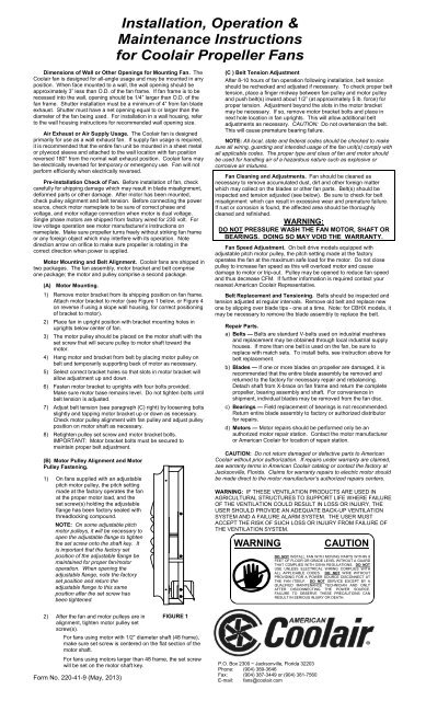
1) Remove motor bracket from its shipping position on fan frame.<br />
Attach motor bracket to motor (see Figure 1 below, or Figure 4<br />
on reverse if using a slope wall housing, for correct positioning<br />
of bracket to motor).<br />
2) Place fan in upright position with bracket mounting holes in<br />
uprights below center of fan.<br />
3) The motor pulley should be placed on the motor shaft with the<br />
set screw that will secure pulley to motor shaft toward the<br />
motor.<br />
4) Hang motor and bracket from belt by placing motor pulley on<br />
belt and temporarily supporting back of motor as necessary.<br />
5) Select correct bracket holes so that slots in motor bracket will<br />
allow adjustment up and down.<br />
6) Fasten motor bracket to uprights with four bolts provided.<br />
Make sure motor base remains level. Do not tighten bolts until<br />
belt tension is adjusted.<br />
7) Adjust belt tension (see paragraph (C) right) by loosening bolts<br />
slightly and tapping motor bracket up or down as necessary.<br />
Check motor pulley alignment with fan pulley and adjust pulley<br />
position on motor shaft as necessary.<br />
8) Retighten pulley set screw and motor bracket bolts.<br />
IMPORTANT: Motor bracket bolts must be secured to<br />
maintain proper belt adjustment.<br />
(B) Motor Pulley Alignment and Motor<br />
Pulley Fastening.<br />
1) On fans supplied with an adjustable<br />
pitch motor pulley, the pitch setting<br />
made at the factory operates the fan<br />
at the proper motor load, and the<br />
set screw(s) holding the adjustable<br />
flange has been factory sealed with<br />
threadlocking compound.<br />
NOTE: On some adjustable pitch<br />
motor pulleys, it will be necessary to<br />
open the adjustable flange to tighten<br />
the set screw onto the shaft key. It<br />
is important that the factory set<br />
position of the adjustable flange be<br />
maintained for proper fan/motor<br />
operation. When opening the<br />
adjustable flange, note the factory<br />
set position and return the<br />
adjustable flange to this same<br />
position after the set screw has<br />
been tightened.<br />
(C ) Belt Tension Adjustment<br />
After 8-10 hours of fan operation following installation, belt tension<br />
should be rechecked and adjusted if necessary. To check proper belt<br />
tension, place a finger midway between fan pulley and motor pulley<br />
and push belt(s) inward about 1/2” (at approximately 5 lb. force) for<br />
proper tension. Adjustment beyond the slots in the motor bracket<br />
may be necessary. If so, remove motor bracket bolts and place in<br />
next hole location in fan uprights. This will allow additional belt<br />
adjustments as necessary. CAUTION: Do not overtension the belt.<br />
This will cause premature bearing failure.<br />
NOTE: All local, state and federal codes should be checked to make<br />
sure all wiring, guarding and intended usage of the fan unit(s) comply with<br />
all applicable codes. The proper type and class of fan and motor should<br />
be used for handling air of a hazardous nature such as explosive or<br />
corrosive air mixtures.<br />
Fan Cleaning and Adjustments. Fan should be cleaned as<br />
necessary to remove accumulated dust, dirt and other foreign matter<br />
which may collect on the blades or other fan parts. Belt(s) should be<br />
inspected and tension adjusted (see below). Be sure to check for belt<br />
misalignment which can result in excessive wear and premature failure.<br />
If rust or corrosion is found, the affected area should be thoroughly<br />
cleaned and refinished.<br />
WARNING:<br />
DO NOT PRESSURE WASH THE FAN MOTOR, SHAFT OR<br />
BEARINGS. DOING SO MAY VOID THE WARRANTY.<br />
Fan Speed Adjustment. On belt drive models equipped with<br />
adjustable pitch motor pulley, the pitch setting made at the factory<br />
operates the fan at the maximum safe load for the motor. Do not close<br />
pulley to increase fan speed as this will overload motor and cause<br />
damage to motor or trip-out. Pulley may be opened to reduce fan speed<br />
and thus decrease CFM. If further information is required contact your<br />
nearest <strong>American</strong> <strong>Coolair</strong> Representative.<br />
Belt Replacement and Tensioning. Belts should be inspected and<br />
tension adjusted at regular intervals. Remove old belt and replace new<br />
one by slipping over blade tips - one at a time. Note: for CBHX models, it<br />
may be necessary to remove the blade assembly to replace the belt.<br />
Repair Parts.<br />
a) Belts — Belts are standard V-belts used on industrial machines<br />
and replacement may be obtained through local industrial supply<br />
houses. If more than one belt is used on the fan, be sure to<br />
replace with match sets. To install belts, see instruction above for<br />
belt replacement.<br />
b) Blades — If one or more blades on propeller are damaged, it is<br />
recommended that the entire blade assembly be removed and<br />
returned to the factory for necessary repair and rebalancing.<br />
Detach shaft from X-brace on fan frame and return the complete<br />
propeller, bearing assembly and shaft. For convenience in<br />
shipment, individual blades may be removed from the fan disc.<br />
c) Bearings — Field replacement of bearings is not recommended.<br />
Return entire blade assembly to factory or authorized distributor<br />
for repairs.<br />
d) Motors — Motor repairs should be performed only be an<br />
authorized motor repair station. Contact the motor manufacturer<br />
or <strong>American</strong> <strong>Coolair</strong> for location of repair station.<br />
CAUTION: Do not return damaged or defective parts to <strong>American</strong><br />
<strong>Coolair</strong> without prior authorization. If repairs under warranty are claimed,<br />
see warranty terms in <strong>American</strong> <strong>Coolair</strong> catalog or contact the factory at<br />
Jacksonville, Florida. Claims for warranty repairs to electric motor should<br />
be made direct to the motor manufacturer’s authorized repairs centers.<br />
WARNING: IF THESE VENTILATION PRODUCTS ARE USED IN<br />
AGRICULTURAL STRUCTURES TO SUPPORT LIFE WHERE FAILURE<br />
OF THE VENTILATION COULD RESULT IN LOSS OR INJURY, THE<br />
USER SHOULD PROVIDE AN ADEQUATE BACK-UP VENTILATION<br />
SYSTEM AND A FAILURE ALARM SYSTEM. THE USER MUST<br />
ACCEPT THE RISK OF SUCH LOSS OR INJURY FROM FAILURE OF<br />
THE VENTILATION SYSTEM.<br />
WARNING<br />
CAUTION<br />
DO NOT INSTALL FAN WITH MOVING PARTS WITHIN 8<br />
FEET OF FLOOR OR GRADE LEVEL WITHOUT A GUARD<br />
THAT COMPLIES WITH OSHA REGULATIONS. DO NOT<br />
USE UNLESS ELECTRICAL WIRING COMPLIES WITH<br />
ALL APPLICABLE CODES. DO NOT WIRE WITHOUT<br />
PROVIDING FOR A POWER SOURCE DISCONNECT AT<br />
THE FAN ITSELF. DO NOT SERVICE EXCEPT BY A<br />
QUALIFIED MAINTENANCE TECHNICIAN AND ONLY<br />
AFTER DISCONNECTING THE POWER SOURCE.<br />
FAILURE TO OBSERVE THESE PRECAUTIONS CAN<br />
RESULT IN SERIOUS INJURY OR DEATH.<br />
2) After the fan and motor pulleys are in<br />
alignment, tighten motor pulley set<br />
screw(s).<br />
FIGURE 1<br />
For fans using motor with 1/2” diameter shaft (48 frame),<br />
make sure set screw is centered on the flat section of the<br />
motor shaft.<br />
For fans using motors larger than 48 frame, the set screw<br />
will be set on the motor shaft key. P.O. Box 2300 ~ Jacksonville, Florida 32203<br />
Phone: (904) 389-3646<br />
Fax: (904) 387-3449 or (904) 381-7560<br />
E-mail: fans@coolair.com<br />
Form No. 220-41-9 (May, 2013)
ASSEMBLY INSTRUCTIONS<br />
Slope Wall Housing for Agricultural Buildings<br />
Fan<br />
Mtg.<br />
Holes<br />
Shutter<br />
Mounting Angle<br />
Right Side<br />
Sheet<br />
Top Sheet<br />
Guard<br />
Clip<br />
Shutter<br />
Mounting<br />
Clip FIGURE 2.<br />
Housing Assembly<br />
See Note 3 For Mounting Instructions<br />
Upper<br />
Mtg.<br />
Angle<br />
Lower<br />
Mtg.<br />
Angle<br />
Side<br />
Mtg.<br />
Angle<br />
FIGURE 3.<br />
Shutter Mounting Angles —<br />
End View<br />
Shutter<br />
Left Side<br />
Sheet<br />
Housing<br />
Mounting<br />
Flange<br />
** NOTE **<br />
Motor Must Be Mounted<br />
at Top of Wall Housing<br />
as Shown<br />
FIGURE 4.<br />
Shutter and Guard Mounting<br />
Guard<br />
1) Before beginning assembly, verify that all components are<br />
present. Each slope wall housing fan package should<br />
consist of a fan and motor, 4 wall housing sheets, 4<br />
shutter mounting angles, 2 or 3 shutter mounting clips, a<br />
shutter and a bag of hardware. The front guard consists of<br />
a wire mesh guard and another bag of hardware. All holes<br />
for assembly of the unit are pre-punched and all necessary<br />
hardware supplied.<br />
2) For the proper mounting of the motor bracket to the fan<br />
frame, disregard Figure 1. Install the motor bracket as<br />
shown in Figure 4 of these instructions. Make sure the<br />
motor is mounted on top of the motor bracket.<br />
3) The shutter mounting angles must be attached to the wall<br />
housing sheets. There are 4 mounting angles of which<br />
two are the same. Identify the mounting angles per Figure<br />
3. There are 4 wall housing sheets—the two that are the<br />
same size are the side sheets. The smaller rectangular<br />
sheet is the bottom. The larger rectangular sheet is the<br />
top. Using 1/4” nuts and bolts, fasten the shutter mounting<br />
angles to their respective housing sheets so that the<br />
turned in flange of the angle is flush with the housing<br />
mounting flange. See Figure 2.<br />
4) Assemble the bottom and one side sheet together using<br />
1/4” nuts and bolts as shown in Figure 2. Then place the<br />
fan on the bottom housing sheet aligning the holes in the<br />
fan flanges with the fan mounting holes in the wall housing<br />
sheets. Caution: For proper shutter clearance, the fan<br />
MUST be mounted in the housing with the motor at the top<br />
of the housing as shown in Figure 4. NOTE: There are<br />
six types of fans that can be used in the wall housing.<br />
They are the type NBF (with either old style welded orifice<br />
or newer spun orifice), NBC, NCF, NEF or FD Fans. For<br />
the old style type NBF fan with the welded orifice ring,<br />
mount the fan in the holes closest to the front of the<br />
housing. For the newer type NBF (with the spun orifice),<br />
NCF, NBC, NEF or FD FANS, mount the fan in the holes<br />
closest to the rear of the housing. See Figure 2. Now,<br />
assemble the remaining housing sheets around the fan<br />
using 1/4” nuts and bolts for the housing assembly and for<br />
mounting the fan panel to the housing. When assembling<br />
the wall housing, do not tighten any hardware until all bolts<br />
are in place or it may be difficult to align some holes.<br />
5) Attach the shutter mounting clips to the bottom shutter<br />
mounting angle using #10 nuts and round head bolts. See<br />
Figure 2. When mounting the shutter to the wall housing,<br />
slide the top shutter flange under the top shutter mounting<br />
angle and then slide the shutter down until the bottom<br />
shutter flange rests between the shutter mounting clip and<br />
the bottom shutter mounting angle. See Figure 4.<br />
6) It will be necessary to bolt the guard clips to the bottom<br />
wall housing sheet. Attach the clips using 1/4” nut and bolt<br />
as shown in Figure 2. The guard can then be mounted to<br />
the front of the wall housing using 1/4” self-tapping screws<br />
and large flat washers. Self-tap through the guard into the<br />
clips on the bottom sheet, and into the pre-punched holes<br />
on the flanges on the top and side sheets. See Figure 4.<br />
ASSEMBLY INSTRUCTIONS<br />
Square Wall Housing for Agricultural Buildings<br />
Shutter<br />
Wall Housing<br />
Panel Mounting Holes<br />
FIGURE 5.<br />
Square Housing Assembly<br />
Rear<br />
Guard<br />
The wall housing consists of four (4) identical panels, which form<br />
the four sides.<br />
1) Lay one wall housing panel down and place fan on it, aligning<br />
the fan panel flange mounting holes with the wall housing panel<br />
mounting holes. If mounting an old style NBF fan (the panel<br />
has a welded orifice ring, not a spun orifice), remove the 3/8”<br />
knock outs 3” in front of the standard wall housing mounting<br />
holes and use them for fan mounting.<br />
2) Using the hardware supplied, assemble all four wall housing<br />
panels around the fan with the wall housing flanges positioned<br />
on the outside of the joint. Note: When assembling the wall<br />
housing, do not tighten any bolts until all the bolts are in place.<br />
Otherwise, there may be difficulty in aligning some bolt holes.<br />
Assemble the fan to the wall housing with the hardware<br />
supplied, using the pre-punched holes in both the fan panel<br />
flanges and the wall housing panels.<br />
3) Next, attach the shutter flanges to the rear of the shutter as<br />
shown in the instructions included with the shutter. Reference<br />
Form 610-40. (S/SR shutters only).<br />
4) Mount the shutter to the front flanges of the wall housing as<br />
shown using 1/4” self-tapping screws supplied.<br />
5) The rear guard should now be installed. It may be mounted to<br />
either the wall housing or the wall. It is mounted to the wall<br />
housing by fastening through the guard into the rear wall<br />
housing flanges as shown using the small pre-punched holes in<br />
the wall housing flanges. The guard can also be mounted<br />
directly to the building, on either side of the wall. The mounting<br />
hardware (1/4” self-tapping screws and large flat washers) for<br />
either installation is supplied with the guard.<br />
6) For a water tight housing, caulk all of the top joints.