us department of transportation federal aviation administration type ...
us department of transportation federal aviation administration type ...
us department of transportation federal aviation administration type ...

Create successful ePaper yourself
Turn your PDF publications into a flip-book with our unique Google optimized e-Paper software.
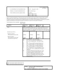
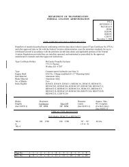
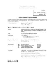
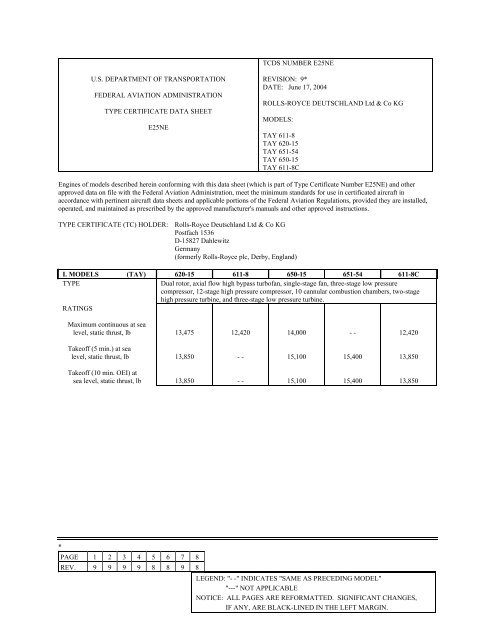
TCDS NUMBER E25NE<br />
U.S. DEPARTMENT OF TRANSPORTATION<br />
FEDERAL AVIATION ADMINISTRATION<br />
TYPE CERTIFICATE DATA SHEET<br />
E25NE<br />
REVISION: 9*<br />
DATE: June 17, 2004<br />
ROLLS-ROYCE DEUTSCHLAND Ltd & Co KG<br />
MODELS:<br />
TAY 611-8<br />
TAY 620-15<br />
TAY 651-54<br />
TAY 650-15<br />
TAY 611-8C<br />
Engines <strong>of</strong> models described herein conforming with this data sheet (which is part <strong>of</strong> Type Certificate Number E25NE) and other<br />
approved data on file with the Federal Aviation Administration, meet the minimum standards for <strong>us</strong>e in certificated aircraft in<br />
accordance with pertinent aircraft data sheets and applicable portions <strong>of</strong> the Federal Aviation Regulations, provided they are installed,<br />
operated, and maintained as prescribed by the approved manufacturer's manuals and other approved instructions.<br />
TYPE CERTIFICATE (TC) HOLDER: Rolls-Royce Deutschland Ltd & Co KG<br />
Postfach 1536<br />
D-15827 Dahlewitz<br />
Germany<br />
(formerly Rolls-Royce plc, Derby, England)<br />
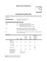
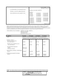
I. MODELS (TAY) 620-15 611-8 650-15 651-54 611-8C<br />
TYPE<br />
Dual rotor, axial flow high bypass turb<strong>of</strong>an, single-stage fan, three-stage low pressure<br />
compressor, 12-stage high pressure compressor, 10 cannular comb<strong>us</strong>tion chambers, two-stage<br />
high pressure turbine, and three-stage low pressure turbine.<br />
RATINGS<br />
Maximum continuo<strong>us</strong> at sea<br />
level, static thr<strong>us</strong>t, lb<br />
13,475<br />
12,420<br />
14,000<br />
- -<br />
12,420<br />
Take<strong>of</strong>f (5 min.) at sea<br />
level, static thr<strong>us</strong>t, lb<br />
13,850<br />
- -<br />
15,100<br />
15,400<br />
13,850<br />
Take<strong>of</strong>f (10 min. OEI) at<br />
sea level, static thr<strong>us</strong>t, lb<br />
13,850<br />
- -<br />
15,100<br />
15,400<br />
13,850<br />
*<br />
PAGE 1 2 3 4 5 6 7 8<br />
REV. 9 9 9 9 8 8 9 8<br />
LEGEND: "- -" INDICATES "SAME AS PRECEDING MODEL"<br />
"---" NOT APPLICABLE<br />
NOTICE: ALL PAGES ARE REFORMATTED. SIGNIFICANT CHANGES,<br />
IF ANY, ARE BLACK-LINED IN THE LEFT MARGIN.
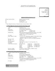
TCDS E25NE PAGE 2<br />
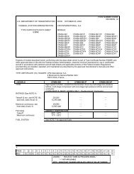
I. MODELS (CONT.) (TAY) 620-15 611-8 650-15 651-54 611-8C<br />
COMPONENTS<br />
FADEC: EEC Goodrich (1)P/N<br />
N/A<br />
N/A<br />
N/A<br />
N/A<br />
TEEC2000-04-AD<br />
Fuel control: Goodrich (1)<br />
or: Goodrich (1) P/N<br />
or: Goodrich (1) P/N<br />
or: Goodrich (1)P/N<br />
CASC501<br />
CASC512<br />
CASC504<br />
CASC514<br />
CASC515<br />
CASC516<br />
CASC506<br />
CASC508<br />
CASC509<br />
CASC510<br />
CASC506<br />
CASC508<br />
FMU1101 &<br />
TMB101<br />
Fuel pump (LP):<br />
FR-HiTemp (2) P/N<br />
BP230/6 MK5<br />
BP230/6 MK5<br />
BP230/6 MK5<br />
BP230/6 MK5<br />
BP230-6 MK5<br />
Fuel pump (HP): Goodrich P/N<br />
GD500<br />
GD501<br />
GD501<br />
GD501<br />
GD502<br />
Ignitor Plugs: Smiths P/N<br />
or: Smiths P/N<br />
1401/RIG 1<br />
1401/RIG 2<br />
1401/RIG 1<br />
1401/RIG 2<br />
1401/RIG 1<br />
1401/RIG 2<br />
1401/RIG 2<br />
or: Champion (3) P/N<br />
or: Champion (3) P/N<br />
(1) formerly TRW and Lucas<br />
(2) formerly Bae Systems & Plessey<br />
(3) formerly Auburn<br />
Y183-5<br />
Y183-5<br />
Y183-5<br />
Y183-6<br />
Y183-5<br />
Y183-6<br />
Y183-5<br />
PRINCIPAL DIMENSIONS, IN.<br />
Length, front flange to rear<br />
flange<br />
Maximum diameter, encircling<br />
94.75<br />
70.72<br />
- -<br />
- -<br />
- -<br />
- -<br />
- -<br />
- -<br />
- -<br />
- -<br />
diameter<br />
WEIGHT (dry) (lbs.) 3,310 3,255 3,516 3,590 3,390<br />
Basic engine with all essential accessories necessary for engine operation, but excludes intake, jet<br />
pipe, and nozzle assembly and hydraulic pumps. Starter is included for models TAY 620-15, 650-<br />
14, 650-15, and 651-54.<br />
CENTER OF GRAVITY, IN.<br />
Aft front s<strong>us</strong>pension centerline<br />
Below engine centerline<br />
Starboard from engine centerline<br />
13.8<br />
3.4<br />
0.6<br />
- -<br />
2.9<br />
0.4<br />
FUEL See NOTE 10<br />
OIL See NOTE 11<br />
Oil Capacity<br />
13.6 Liter/5.1 Liter <strong>us</strong>able<br />
14.2<br />
3.3<br />
0.6<br />
14.5<br />
3.5<br />
- -<br />
14.3<br />
2.1<br />
-0.8
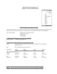
TCDS E25NE PAGE 3<br />
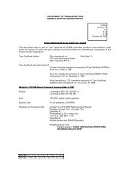
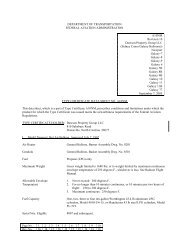
CERTIFICATION BASIS<br />
FARs 21.29 and 33 effective Feb. 1, 1965, amended by FAR 33-1 through 33-9 for the TAY<br />
620-15, 611-8, 650-15, and 651-54 engine models.<br />
Pursuant to FAR 21.29(a)(1)(ii), Type Certificate E25NE was issued in validation <strong>of</strong> the British<br />
Civil Aviation Authority's certification <strong>of</strong> compliance with BCAR standards, which were found<br />
to provide a level <strong>of</strong> safety equivalent to the above "Certification Basis", as follows:<br />
JAR-E, Change 6, dated Aug<strong>us</strong>t 28, 1981 (BCAR Section C, Issue 13)<br />
FARs 21.29 and 33, effective Feb. 1, 1965, amended by FAR 33-1 through 33-9, 33.28,<br />
Amendment 15, 33.76, Amendment 20, 33.78, Amendment 19, 33.88, Amendment 18 and FAR<br />
34, Amendment 3 for the TAY 611-8C engine model.<br />
DATE OF DATE TC ISSUED DATE TC<br />
MODEL APPLICATION OR REVISED CANCELLED<br />
TAY 610-8 MAR 06, 1984 OCT 30, 1986 OCT 21, 2002<br />
TAY 620-15 MAR 06, 1984 OCT 30, 1986<br />
TAY 611-8 SEP 09, 1987 OCT 15, 1987<br />
TAY 611-8B MAY 02, 1989 JUN 30, 1989 OCT 21, 2002<br />
TAY 650-14 JAN 26, 1988 MAR 16, 1990 OCT 21, 2002<br />
TAY 650-15 JUN 02, 1987 OCT 05, 1988<br />
TAY 651-54 MAR 20, 1991 MAY 20, 1992<br />
TAY 611-8C DEC 12, 2001 MAR 5, 2003<br />
IMPORT REQUIREMENTS<br />
To be considered for installation on United States-registered aircraft, each engine (or propeller)<br />
to be exported to the United States shall be accompanied by a certificate <strong>of</strong> airworthiness for<br />
export, or certifying statement endorsed by the exporting cognizant civil airworthiness authority,<br />
which contains the following language:<br />
(1) This engine (or propeller) conforms to its United States <strong>type</strong> design (Type<br />
Certification Number E25NE) and is in a condition for safe operation.<br />
(2) This engine (or propeller) has been subjected by the manufacturer to a final<br />
operational check and is in a proper state <strong>of</strong> airworthiness.<br />
Reference FAR Section 21.500, which provides for the airworthiness acceptance <strong>of</strong> aircraft<br />
engines or propellers manufactured outside <strong>of</strong> the United States for which a United States <strong>type</strong><br />
certificate has been issued.<br />
Additional guidance is contained in FAA Advisory Circular 21-23, Airworthiness Certification<br />
<strong>of</strong> Civil Aircraft, Engines, Propellers, and Related Products, Imported into the United States.<br />
Service bulletins, structural repair manuals, vendor manuals, aircraft flight manuals, and overhaul<br />
and maintenance manuals which contain a statement that the document is LBA/CAA-approved<br />
are accepted by the FAA and are considered FAA-approved. These approvals pertain to the <strong>type</strong><br />
design only.
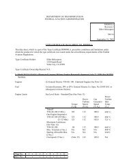
TCDS E25NE PAGE 4<br />
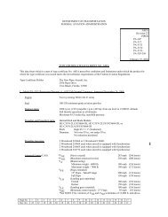
NOTES<br />
I. MODELS (TAY) 620-15 611-8 650-15 651-54 611-8C<br />
NOTE 1. MAXIMUM PERMISSIBLE ENGINE OPERATING SPEEDS (See NOTES 8, 14, and 18)<br />
Models 611-8, 611-8C<br />
100% HP=12,484 rpm, 100% LP=8,393 rpm<br />
Models 620-15, 650-15, 651-54<br />
100% HP=12,136 rpm, 100% LP=8,393 rpm<br />
LOW PRESSURE ROTOR<br />
(N1)<br />
Take<strong>of</strong>f (5 min.)<br />
Take<strong>of</strong>f (10 min. OEI)<br />
Maximum continuo<strong>us</strong><br />
Transient (20 sec.)<br />
Maximum for reverse thr<strong>us</strong>t<br />
8,100<br />
8,100<br />
8,100<br />
8,343<br />
8,015<br />
8,015<br />
8,015<br />
8,250<br />
- -<br />
- -<br />
- -<br />
- -<br />
- -<br />
- -<br />
- -<br />
- -<br />
- -<br />
- -<br />
- -<br />
8,100<br />
5,457<br />
HIGH PRESSURE ROTOR<br />
(N2)<br />
Take<strong>of</strong>f (5 min.)<br />
Take<strong>of</strong>f (10 min. OEI)<br />
Maximum continuo<strong>us</strong><br />
Transient (20 sec.)<br />
Minimum idle, ground<br />
and flight<br />
Maximum for reverse<br />
thr<strong>us</strong>t<br />
12,560<br />
12,560<br />
12,197<br />
12,937<br />
5,813<br />
11,602<br />
12,446<br />
12,446<br />
12,172<br />
12,809<br />
5,818<br />
11,485<br />
12,560<br />
12,560<br />
12,197<br />
12,937<br />
5,813<br />
11,310<br />
12,670<br />
12,670<br />
- -<br />
- -<br />
- -<br />
11,650<br />
12,560<br />
12,560<br />
12,172<br />
12,684<br />
6,130<br />
N/A<br />
NOTE 2. MAXIMUM PERMISSIBLE TEMPERATURES (See NOTE 14)<br />
TURBINE GAS TEMP. Measured at first stage low pressure turbine nozzle guide vane<br />
o C/ o F<br />
o C/ o F<br />
o C/ o F<br />
o C/ o F<br />
Take<strong>of</strong>f (5 min.)<br />
800/1472<br />
- -<br />
850/1562 865/1589<br />
Take<strong>of</strong>f (10 min. OEI)<br />
800/1472<br />
- -<br />
850/1562 865/1589<br />
Maximum continuo<strong>us</strong><br />
735/1355 715/1319 795/1463<br />
- -<br />
Overtemperature (20 sec.) 820/1508<br />
- -<br />
870/1598 885/1625<br />
Starting, ground (2 sec.)<br />
700/1292<br />
- -<br />
740/1364<br />
- -<br />
Starting, inflight (2 sec.) 780/1436<br />
- -<br />
780/1436<br />
- -<br />
FUEL TEMPERATURE Measured at inlet to high pressure stage <strong>of</strong> fuel pump (See NOTE 10)<br />
o C/ o F<br />
o C/ o F<br />
o C/ o F<br />
o C/ o F<br />
Continuo<strong>us</strong> operation<br />
90/194<br />
- -<br />
95/203<br />
- -<br />
Transient operation (15 min.) 120/248<br />
- -<br />
130/266<br />
- -<br />
°C/°F<br />
800/1472<br />
800/1472<br />
715/1319<br />
820/1508<br />
700/1292<br />
- -<br />
°C/°F<br />
- -<br />
- -<br />
OIL INLET<br />
TEMPERATURE<br />
Continuo<strong>us</strong> operation<br />
Transient operation (15 min.)<br />
Measured at oil pump exit (See NOTE 11)<br />
o C/ o F<br />
105/221<br />
120/248<br />
o C/ o F<br />
- -<br />
- -<br />
o C/ o F<br />
- -<br />
- -<br />
o C/ o F<br />
- -<br />
- -<br />
°C/°F<br />
- -<br />
120/248<br />
NOTE 3.<br />
FUEL<br />
Minimum operation<br />
Minimum starting<br />
Maximum<br />
OIL<br />
Minimum for take<strong>of</strong>f<br />
Maximum continuo<strong>us</strong><br />
Idle to 9500 rpm (1)<br />
FUEL AND OIL PRESSURE LIMITS / ALL MODELS<br />
Measured at inlet to low pressure stage <strong>of</strong> fuel pump<br />
12 psia or 6 psi above tank pressure, which ever is lower, but not less than 2 psig<br />
10 psia<br />
40 psig<br />
Measured at oil pump exit.<br />
30 psig<br />
25 psig<br />
16 psig<br />
(1) Oil pressure increase follows a straight line relationship between 9500 rpm N2<br />
and maximum continuo<strong>us</strong> condition.
TCDS E25NE PAGE 5<br />
I. MODELS (TAY) 620-15 611-8 650-15 651-54 611-8C<br />
NOTE 4.<br />
MAXIMUM PERMISSIBLE AIR BLEED EXTRACTIONS<br />
Compressor air bleed may be <strong>us</strong>ed in accordance with Rolls-Royce instructions such that the<br />
operating limitations are not exceeded, up to either the individual or combined non-dimensional<br />
bleed extraction defined. Bleed air for nose cowl anti-icing is included.<br />
T1 = total temperature at engine intake ( o K)<br />
P1 = total pressure at engine intake (psia)<br />
M7 = HP stage 7 <strong>of</strong>ftake mass flow (lb/sec)<br />
M12 = HP stage 12 <strong>of</strong>ftake mass flow (lb/sec)<br />
MT = M7+M12 <strong>of</strong>ftake mass flow (lb/sec)<br />
MF = LP (fan) <strong>of</strong>ftake mass flow (lb/sec)<br />
7th-Stage HPC Bleed<br />
((M7)(T1**.5))/P1<br />
Maximum take<strong>of</strong>f<br />
Maximum continuo<strong>us</strong><br />
and below<br />
12th-Stage HPC Bleed<br />
((M12)(T1**.5))/P1<br />
Maximum take<strong>of</strong>f<br />
Maximum continuo<strong>us</strong><br />
and below<br />
HPC Total Bleed<br />
((MT)(T1**.5))/P1<br />
Maximum take<strong>of</strong>f (a)<br />
Maximum continuo<strong>us</strong><br />
and below (b)<br />
Fan Bleed ((MF)(T1**.5))/P1<br />
Maximum take<strong>of</strong>f<br />
Maximum continuo<strong>us</strong><br />
and below<br />
(a)<br />
(b)<br />
7.0<br />
7.0<br />
---<br />
10.0<br />
7.0<br />
10.0<br />
10.5<br />
10.5<br />
- -<br />
- -<br />
- -<br />
- -<br />
- -<br />
- -<br />
--<br />
--<br />
- -<br />
- -<br />
- -<br />
- -<br />
- -<br />
- -<br />
6.5<br />
6.5<br />
9.69<br />
9.10<br />
- -<br />
12.9<br />
9.69<br />
12.9<br />
14.51<br />
13.94<br />
For maximum take<strong>of</strong>f, the bleed air may be extracted from 7th stage only.<br />
For maximum continuo<strong>us</strong>, the bleed air may be extracted either from 12th<br />
stage or from combination <strong>of</strong> 7th and 12th stages.<br />
7.0<br />
7.0<br />
- -<br />
6.9<br />
7.0<br />
10.0<br />
10.5<br />
10.5<br />
NOTE 5.<br />
BASIS OF RATINGS<br />
Use <strong>of</strong> the 10-minute one engine inoperative (OEI) take<strong>of</strong>f rating is approved for <strong>us</strong>e only in the<br />
event <strong>of</strong> an inoperative engine(s) due to shutdown or failure, and is limited to periods <strong>of</strong> not more<br />
than 10-minutes. Take<strong>of</strong>f thr<strong>us</strong>t under normal conditions, i.e. when all engines are operative, is<br />
limited to periods <strong>of</strong> not more than 5-minutes.<br />
Ratings are based on static test stand operation under the following conditions:<br />
(a) compressor inlet air at 15øC (59øF) and 29.92 in-Hg<br />
(b) Rolls-Royce test bed flaremeter TA1, TA2 or TA3 (ATF9476) for the TAY 611-8 and<br />
620-15 and TA10 or TA11 (ATF10173) for the TAY 650-15, 651-54 and 611-8C.<br />
(c) Rolls-Royce Jet Pipe/Final Nozzle Assembly JP2 or JP3 (ATF9786) for the TAY 611-8<br />
and 620-15, 650-15 and 651-54 and JP4 or JP5 (ATF9786) for the TAY 611-8C.<br />
(d) turbine gas temperature measured by 9 pairs <strong>of</strong> thermocouples mounted in<br />
the first stage low pressure turbine nozzle guide vane (NGV) with ballast<br />
resistor, specified in the applicable engine manual<br />
(e) no aircraft accessory loads or bleed air extraction<br />
(f) turbine gas temperature limits and engine rotor speed limits are not exceeded<br />
(g) 100% air intake recovery
TCDS E25NE PAGE 6<br />
NOTE 6.<br />
DRIVE<br />
Starter<br />
All models<br />
Main Hydraulic pump<br />
611-8 /611-8C<br />
620-15 / 650-15<br />
651-54<br />
Auxiliary hydraulic pump<br />
620-15 / 650-15<br />
IDG<br />
620-15 / 650-15<br />
611-8C<br />
AC generator<br />
611-8<br />
ACCESSORY DRIVE PROVISIONS<br />
Speed Ratio<br />
TORQUE (lb - in)<br />
To HP<br />
Rotation Rotor Speed Maximum Continuo<strong>us</strong> Instantaneo<strong>us</strong><br />
CW<br />
CCW<br />
CCW<br />
CW<br />
CW<br />
CW<br />
CW<br />
CCW<br />
1.0398<br />
0.2615<br />
0.3397<br />
0.2880<br />
0.3176<br />
0.5088<br />
0.5088<br />
0.8821<br />
2592<br />
732<br />
461<br />
732<br />
176<br />
659<br />
659<br />
500<br />
2981<br />
3000<br />
1455<br />
3000<br />
500<br />
4286<br />
7140<br />
2310<br />
Overhang<br />
(lb - in)<br />
153<br />
140<br />
36<br />
140<br />
11<br />
743<br />
743<br />
250<br />
CSD and alternator<br />
651-54<br />
CW<br />
0.6846<br />
1230<br />
NOTES: CW = clockwise, looking into the appropriate gearbox face<br />
CCW = counter-clockwise<br />
5900<br />
2154<br />
NOTE 7.<br />
NOTE 8.<br />
NOTE 9.<br />
NOTE 10.<br />
Thr<strong>us</strong>t setting, thr<strong>us</strong>t check and control <strong>of</strong> engine output in all operations are to be based on Rolls-<br />
Royce engine charts included in the relevant operating instructions. On the hydromechanically<br />
controlled engines, pressure ratio (EPR) indication is not reliable as the primary thr<strong>us</strong>t setting<br />
parameter due to the EPR probe's s<strong>us</strong>ceptibility to icing. N1 thr<strong>us</strong>t setting procedures m<strong>us</strong>t be <strong>us</strong>ed<br />
for the TAY 620-15 model unless the EPR probes are modified in accordance with Rolls-Royce<br />
Service Bulletins 75-1036 and 75-1055 or the equivalent and with appropriate EPR thr<strong>us</strong>t setting<br />
charts.<br />
For inflight operation during icing conditions, the minimum allowable fan speed (N1) for the TAY<br />
611-8C is 21.1% (1770rpm) and for the other variants is 21% (1760 rpm).<br />
Certain engine parts are life-limited. These parts are listed in time limit section <strong>of</strong> the relevant<br />
Engine Manuals. Maintenance is to be carried out in accordance with the manual (See NOTE 12).<br />
Approved fuels and fuel additives are listed in the appropriate Rolls-Royce Operating Instructions<br />
(See NOTE 12.)<br />
For the TAY 611-8and 651-54 and 611-8C, minimum fuel temperature measured at inlet to low<br />
pressure stage <strong>of</strong> fuel pump is -40°C(-40°F).<br />
For the TAY 620-15and 650-15, minimum fuel temperature measured at inlet to low pressure stage<br />
<strong>of</strong> fuel pump is -50°C(-58°F).<br />
NOTE 11.<br />
Approved oils are listed in the appropriate Rolls-Royce Operating Instructions (See NOTE 12). Oils<br />
<strong>of</strong> the approved <strong>type</strong>s when reclaimed to the approved Rolls-Royce standards are approved for <strong>us</strong>e.<br />
Minimum oil temperatures, measured at oil pump exit, are as follows:<br />
TAY MODEL<br />
611-8 / 611-8C<br />
620-15 / 650-15<br />
651-54<br />
MINIMUM OIL TEMPERATURE<br />
ACCELERATION<br />
STARTING FROM IDLE<br />
o C<br />
-40<br />
-50<br />
-40<br />
o F<br />
-40<br />
-58<br />
-40<br />
o C<br />
-30<br />
-30<br />
-30<br />
o F<br />
-22<br />
-22<br />
-22
TCDS E25NE PAGE 7<br />
NOTE 12. TAY MODEL OPERATING<br />
INSTRUCTIONS<br />
MAINTENANCE<br />
MANUAL<br />
ENGINE<br />
MANUAL<br />
INSTALLATION<br />
MANUAL<br />
611-8<br />
F-TAY-1RR<br />
M-TAY-1RR<br />
E-TAY-1RR<br />
EL2825<br />
620-15<br />
F-TAY-2RR<br />
M-TAY-2RR<br />
E-TAY-2RR<br />
EL1716<br />
650-15<br />
F-TAY-3RR<br />
M-TAY-3RR<br />
E-TAY-3RR<br />
EL2823<br />
651-54<br />
F-TAY-5RR<br />
M-TAY-5RR<br />
E-TAY-5RR<br />
EL2834<br />
611-8C<br />
F-TAY-6RR<br />
M-TAY-6RR<br />
E-TAY-6RR<br />
O-TR0817/03<br />
NOTE 13.<br />
NOTE 14.<br />
NOTE 15.<br />
These engines meet the smoke, fuel venting, and gaseo<strong>us</strong> emission requirements <strong>of</strong> SAFR 27-5 dated<br />
January 1, 1984. The TAY 611-8C meets the requirements <strong>of</strong> FAR 34 amendment 3 (ICAO Annex<br />
16, Volume 11, Second Edition, July 1993).<br />
Limits regarding transient rotor shaft overspeed and transient gas temperature and number <strong>of</strong><br />
occurrences are specified in the appropriate Rolls-Royce Maintenance Manual (See NOTE 12).<br />
The engines are approved for <strong>us</strong>e to the following ambient temperatures in Column 1 and 2 and are<br />
flat rated to the values in column 3 and 4.<br />
TAY MODEL<br />
611-8<br />
MAXIMUM<br />
AMBIENT<br />
o C<br />
o F<br />
55 131<br />
FLAT<br />
TAKEOFF<br />
o C<br />
o F<br />
30<br />
86<br />
620-15<br />
55<br />
131<br />
30<br />
86<br />
650-15<br />
55<br />
131<br />
30<br />
86<br />
651-54<br />
50<br />
122<br />
30<br />
86<br />
611-8C<br />
52<br />
131<br />
30<br />
86<br />
NOTE 16.<br />
NOTE 17.<br />
NOTE 18.<br />
The maximum inlet throat area <strong>of</strong> the engines including aircraft air intake is limited to 1405 square<br />
inches for the TAY 611-8C and 1500 square inches for all other variants.<br />
The maximum engine inlet distortion limit is specified in the appropriate Rolls-Royce Installation<br />
Manual (See NOTE 12).<br />
The limits quoted are relative to the engines equipped with one <strong>of</strong> the following thr<strong>us</strong>t reverser <strong>type</strong>s.<br />
TAY 611-8: Grumman Aerospace <strong>type</strong> 1159P41460-1 / -2<br />
TAY 620-15:<br />
Grumman Aerospace <strong>type</strong> 1159P41530-1 / -2 / -9 /-10 and<br />
1159RDP41530-51 / -52.<br />
TAY 650-15: Grumman Aerospace <strong>type</strong> 1159RDP41530-7 / -8 / -9 / -10.<br />
TAY 651-54:<br />
TAY 611-8C:<br />
Dee Howard thr<strong>us</strong>t reverser <strong>type</strong> TR6510 with the engine side mount<br />
configuration, and Dee Howard jet pipe P/N Qf 781.1000 for center engine<br />
mount configuration.<br />
Nordam thr<strong>us</strong>t reverser P/N 08ND78006-1 for left hand installation and P/N<br />
08ND78006-2 for right hand installation.<br />
Approval for operation in reverse thr<strong>us</strong>t does not imply approval <strong>of</strong> the thr<strong>us</strong>t reversers themselves.
TCDS E25NE PAGE 8<br />
NOTE 19.<br />
These engine models incorporate the following general characteristics:<br />
610-8: Base Engine with Installation features to suit Gulfstream IV series aircraft.<br />
No longer in service.<br />
TAY 620-15:<br />
Same as 610-8, except take<strong>of</strong>f and maximum continuo<strong>us</strong> static thr<strong>us</strong>t increase<br />
at sea level flat rated to 86°F ambient temperature. Installation features to suit<br />
Fokker 70 and Fokker 100 series aircraft.<br />
TAY 611-8:<br />
Same as 610-8, except take<strong>of</strong>f static thr<strong>us</strong>t increase at sea level flat rated to<br />
86°F ambient temperature. Installation features to suit Gulfstream IV and<br />
IV-SP series aircraft.<br />
TAY 650-15:<br />
Same as 620-15, except with increased diameter fan, improved comb<strong>us</strong>tors,<br />
new high pressure turbine blades and vanes, and other minor hardware changes<br />
to accommodate higher thr<strong>us</strong>t. Installation features to suit Fokker 100 series<br />
aircraft.<br />
TAY 651-54:<br />
TAY 611-8C:<br />
Same as 650-15, except with installation features and gearbox to suit the<br />
Boeing 727-100 series aircraft and either a Dee Howard thr<strong>us</strong>t reverser (sidemounted<br />
engines) or a Dee Howard jet pipe P/N Qf 781.1000 (center engine).<br />
Same as 611-8, except with Fan system from TAY 650-15 and the introduction<br />
Of a FADEC control system.<br />
----END----