Cooper-Wheelock E Series - Advanced Alarm Systems
Cooper-Wheelock E Series - Advanced Alarm Systems
Cooper-Wheelock E Series - Advanced Alarm Systems

Create successful ePaper yourself
Turn your PDF publications into a flip-book with our unique Google optimized e-Paper software.
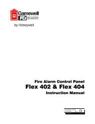
<strong>Cooper</strong>-<strong>Wheelock</strong> E <strong>Series</strong><br />
Low-Profile Speakers & Speaker Strobes<br />
Features<br />
• ADA/NFPA/UFC/ANSI compliant<br />
• Complies with OSHA 29 Part 1910.165<br />
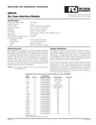
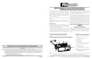
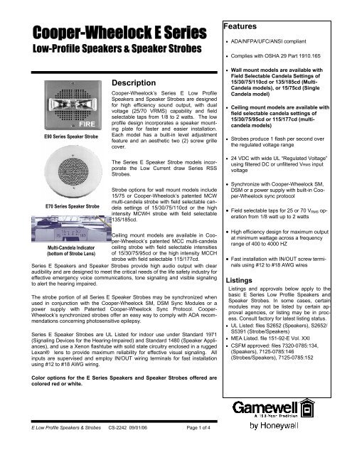
E90 <strong>Series</strong> Speaker Strobe<br />
E70 <strong>Series</strong> Speaker Strobe<br />
Description<br />
<strong>Cooper</strong>-<strong>Wheelock</strong>’s <strong>Series</strong> E Low Profile<br />
Speakers and Speaker Strobes are designed<br />
for high efficiency sound output, with dual<br />
voltage (25/70 VRMS) capability and field<br />
selectable taps from 1/8 to 2 watts. The low<br />
profile design incorporates a speaker mounting<br />
plate for faster and easier installation.<br />
Each model has a built-in level adjustment<br />
feature and an aesthetic two (2) screw grille<br />
cover.<br />
The <strong>Series</strong> E Speaker Strobe models incorporate<br />
the Low Current draw <strong>Series</strong> RSS<br />
Strobes.<br />
Strobe options for wall mount models include<br />
15/75 or <strong>Cooper</strong>-<strong>Wheelock</strong>’s patented MCW<br />
multi-candela strobe with field selectable candela<br />
settings of 15/30/75/110cd or the high<br />
intensity MCWH strobe with field selectable<br />
135/185cd.<br />
• Wall mount models are available with<br />
Field Selectable Candela Settings of<br />
15/30/75/110cd or 135/185cd (Multi-<br />
Candela models), or 15/75cd (Single<br />
Candela model)<br />
• Ceiling mount models are available with<br />
field selectable candela settings of<br />
15/30/75/95cd or 115/177cd (multicandela<br />
models)<br />
• Strobes produce 1 flash per second over<br />
the regulated voltage range<br />
• 24 VDC with wide UL “Regulated Voltage”<br />
using filtered DC or unfiltered VRMS input<br />
voltage<br />
• Synchronize with <strong>Cooper</strong>-<strong>Wheelock</strong> SM,<br />
DSM or a power supply with built-in <strong>Cooper</strong>-<strong>Wheelock</strong><br />
sync protocol<br />
• Field selectable taps for 25 or 70 V RMS operation<br />
from 1/8 watt up to 2 watts<br />
Multi-Candela Indicator<br />
(bottom of Strobe Lens)<br />
Ceiling mount models are available in <strong>Cooper</strong>-<strong>Wheelock</strong>’s<br />
patented MCC multi-candela<br />
ceiling strobe with field selectable intensities<br />
of 15/30/75/95cd or the high intensity MCCH<br />
strobe with field selectable 115/177cd.<br />
<strong>Series</strong> E Speakers and Speaker Strobes provide high audio output with clear<br />
audibility and are designed to meet the critical needs of the life safety industry for<br />
effective emergency voice communications, tone signaling and visible signaling<br />
to alert the hearing impaired.<br />
The strobe portion of all <strong>Series</strong> E Speaker Strobes may be synchronized when<br />
used in conjunction with the <strong>Cooper</strong>-<strong>Wheelock</strong> SM, DSM Sync Modules or a<br />
power supply with Patented <strong>Cooper</strong>-<strong>Wheelock</strong> Sync Protocol. <strong>Cooper</strong>-<br />
<strong>Wheelock</strong>’s synchronized strobes offer an easy way to comply with ADA recommendations<br />
concerning photosensitive epilepsy.<br />
<strong>Series</strong> E Speaker Strobes are UL Listed for indoor use under Standard 1971<br />
(Signaling Devices for the Hearing-Impaired) and Standard 1480 (Speaker Appliances),<br />
and use a Xenon flashtube with solid state circuitry enclosed in a rugged<br />
Lexan® lens to provide maximum reliability for effective visual signaling. All<br />
inputs are supervised and employ IN/OUT wiring terminals for fast installation<br />
using #12 to #18 AWG wiring.<br />
• High efficiency design for maximum output<br />
at minimum wattage across a frequency<br />
range of 400 to 4000 HZ<br />
• Fast installation with IN/OUT screw terminals<br />
using #12 to #18 AWG wires<br />
Listings<br />
Listings and approvals below apply to the<br />
basic E <strong>Series</strong> Low Profile Speakers and<br />
Speaker Strobes. In some cases, certain<br />
modules may not be listed by certain approval<br />
agencies, or listing may be in process.<br />
Consult factory for latest listing status.<br />
• UL Listed: files S2652 (Speakers), S2652/<br />
S5391 (Strobe/Speakers)<br />
• MEA Listed. file 151-92-E Vol. XXI<br />
• CSFM approved: files 7320-0785:134,<br />
(Speakers), 7125-0785:146<br />
(Strobes/Speakers), 7125-0785:152<br />
Color options for the E <strong>Series</strong> Speakers and Speaker Strobes offered are<br />
colored red or white.<br />
E Low Profile Speakers & Strobes CS-2242 09/01/06 Page 1 of 4
General Notes<br />
• Strobes are designed to flash once per second minimum over their “Regulated<br />
Voltage Range”. Note that NFPA-72 specifies a flash rate of 1 to 2 flashes per<br />
second and ADA Guidelines specify a flash rate of 1 to 3 flashes per second.<br />
• All candela ratings represent min. effective Strobe intensity per UL Standard 1971.<br />
• <strong>Series</strong> E Speaker Strobes and <strong>Series</strong> E Speakers are listed under UL Standard<br />
1971 for indoor use with a temperature range of 32°F to 120°F (0°C to 49°C) and<br />
maximum humidity of 85%.<br />
• “Regulated Voltage Range” is the newest terminology used by UL to identify<br />
voltage range. Prior to this change, UL used the term, “Listed Voltage<br />
Range”.<br />
Engineer’s Specifications<br />
The speaker appliances shall be <strong>Cooper</strong>-<strong>Wheelock</strong> <strong>Series</strong> E Speakers and<br />
speaker strobe appliances shall be <strong>Cooper</strong>-<strong>Wheelock</strong> <strong>Series</strong> E Speaker Strobes or<br />
approved equals. The speakers shall be UL Listed under Standard 1480 for Fire<br />
Protective Service and speakers equipped with strobes shall be listed under UL<br />
Standard 1971 for Signaling Devices for the Hearing-Impaired. In addition, the<br />
strobes shall be certified to meet the requirements of FCC Part 15, Class B.<br />
All speakers shall be designed for a field selectable input of either 25 or 70 V RMS ,<br />
with selectable power taps from 1/8 watt to 2 watts. All models shall have listed<br />
sound output of up to 87 dB at 10 feet and a listed frequency response of 400 to<br />
4000 Hz. The speaker shall also incorporate a sealed back construction. All inputs<br />
shall employ terminals that accept #12 to #18 AWG wire sizes.<br />
The strobe portion of the appliance shall produce a flash rate of one (1) flash per<br />
second over the Regulated Voltage Range and shall incorporate a Xenon flashtube<br />
enclosed in a rugged Lexan® lens. The strobe shall be of low current design.<br />
Where, Multi-Candela Speaker Strobes are specified, the strobe intensity has field<br />
selectable settings and shall be rated per UL Standard 1971 at 15/30/75/110cd or<br />
135/185cd for wall mount and 15/30/75/95cd or 115/177cd for ceiling mount. The<br />
selector switch for selecting the candela shall be tamper resistant. The 15/75 candela<br />
strobe shall be specified when 15 candela UL Standard 1971 listing with 75<br />
candela on-axis is required (ADA compliance).<br />
When synchronization is required, the strobe portion of the appliance shall be compatible<br />
with <strong>Cooper</strong>-<strong>Wheelock</strong>’s SM, DSM sync modules or the power supply with<br />
built-in Patented <strong>Cooper</strong>-<strong>Wheelock</strong> Sync Protocol. The strobes shall not drift out of<br />
synchronization at any time during operation. If the sync module or Power Supply<br />
fails to operate, (i.e., contacts remain closed), the strobe shall revert to a nonsynchronized<br />
flash rate.<br />
The speaker and speaker strobe appliances shall be designed for indoor surface or<br />
flush mounting. The speaker and speaker strobe shall incorporate a speaker<br />
mounting plate with a grille cover which is secured with two screws for a level, aesthetic<br />
finish and shall mount to standard electrical hardware requiring no additional<br />
trimplate or adapter. The finish of the <strong>Series</strong> E speakers and speaker strobes shall<br />
be white, red or nickel plate. All speakers and speaker strobe appliances shall be<br />
<strong>Cooper</strong>-<strong>Wheelock</strong> products must be used within their published specifications and<br />
must be PROPERLY specified, applied, installed, operated, maintained and operationally<br />
tested in accordance with their installation instructions at the time of installation<br />
and at least twice a year or more often and in accordance with local, state<br />
and federal codes, regulations and laws. Specification, application, installation,<br />
operation, maintenance and testing must be performed by qualified personnel for<br />
proper operation in accordance with all of the latest National Fire Protection Association<br />
(NFPA), Underwriters’ Laboratories (UL), National Electrical Code (NEC),<br />
Occupational Safety and Health Administration (OSHA), local, state, county, province,<br />
district, federal and other applicable building and fire standards, guidelines,<br />
regulations, laws and codes including, but not limited to, all appendices and<br />
amendments and the requirements of the local authority having jurisdiction (AHJ).<br />
E Low Profile Speakers & Strobes CS-2242 09/01/06 Page 2 of 4<br />
WARNING: CONTACT COOPER-WHEELOCK<br />
FOR THE CURRENT “INSTALLATION IN-<br />
STRUCTIONS” AND “GENERAL INFORMA-<br />
TION” SHEET (P82380) ON THESE PRODUCTS.<br />
THESE DOCUMENTS UNDERGO PERIODIC<br />
CHANGES. IT IS IMPORTANT THAT YOU HAVE<br />
CURRENT INFORMATION ON THESE PROD-<br />
UCTS. THESE MATERIALS CONTAIN IMPOR-<br />
TANT INFORMATION THAT SHOULD BE READ<br />
PRIOR TO SPECIFYING OR INSTALLING<br />
THESE PRODUCTS, INCLUDING:<br />
• TOTAL CURRENT REQUIRED BY ALL<br />
APPLIANCES CONNECTED TO SYSTEM<br />
SECONDARY POWER SOURCES.<br />
• FUSE RATINGS ON NOTIFICATION<br />
APPLIANCE CIRCUITS TO HANDLE PEAK<br />
CURRENTS FROM ALL APPLIANCES ON<br />
THOSE CIRCUITS.<br />
• COMPOSITE FLASH RATE FROM MULTIPLE<br />
STROBES WITHIN A PERSON’S FIELD OF<br />
VIEW.<br />
• ADDING, REPLACING OR CHANGING<br />
APPLIANCES OR CHANGING CANDELA<br />
SETTINGS WILL AFFECT CURRENT DRAW.<br />
RECALCULATE CURRENT DRAW TO<br />
ENSURE THAT THE TOTAL AVERAGE CUR-<br />
RENT AND TOTAL PEAK REQUIRED BY ALL<br />
APPLIANCES DO NOT EXCEED THE RATED<br />
CAPACITY OF THE POWER SOURCES OR<br />
FUSES.<br />
• THE VOLTAGE APPLIED TO THESE<br />
PRODUCTS MUST BE WITHIN THEIR<br />
“REGULATED VOLTAGE RANGE”.<br />
• INSTALLATION OF 110 CANDELA STROBE<br />
PRODUCTS IN SLEEPING AREAS.<br />
• INSTALLATION IN OFFICE AREAS AND<br />
OTHER SPECIFICATION AND INSTALLA-<br />
TION ISSUES.<br />
• USE STROBES ONLY ON CIRCUITS WITH<br />
CONTINUOUSLY APPLIED OPERATING<br />
VOLTAGE. DO NOT USE STROBES ON<br />
CODED OR INTERRUPTED CIRCUITS IN<br />
WHICH THE APPLIED VOLTAGE IS CYCLED<br />
ON AND OFF AS THE STROBES MAY NOT<br />
FLASH.<br />
• FAILURE TO COMPLY WITH THE<br />
INSTALLATION INSTRUCTIONS OR GEN-<br />
ERAL INFORMATION SHEETS COULD RE-<br />
SULT IN IMPROPER INSTALLATION, APPLI-<br />
CATION, AND/OR OPERATION OF THESE<br />
PRODUCTS IN AN EMERGENCY SITUA-<br />
TION, WHICH COULD RESULT IN PROP-<br />
ERTY DAMAGE AND SERIOUS INJURY OR<br />
DEATH TO YOU AND/OR OTHERS.<br />
• CONDUCTOR SIZE (AWG), LENGTH AND<br />
AMPACITY SHOULD BE TAKEN INTO CON-<br />
SIDERATION PRIOR TO DESIGN AND IN-<br />
STALLATION OF THESE PRODUCTS, PAR-<br />
TICULARLY IN RETROFIT INSTALLATIONS.
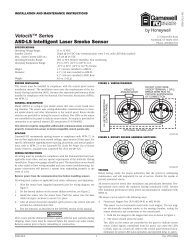
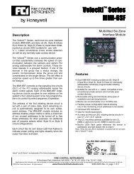
Wiring Diagram<br />
SERIES E SPEAKER & STROBE<br />
OPERATE INDEPENDENTLY<br />
(NON-SYNC OR SYNC)<br />
+<br />
FROM<br />
PRECEDING<br />
APPLIANCE -<br />
OR VOICE<br />
EVACUATION<br />
PANEL<br />
FROM<br />
PRECEDING<br />
STROBE, SYNC-<br />
MODULE, POWER<br />
SUPPLY OR<br />
FACP<br />
+ - + -<br />
STROBE<br />
SPEAKER<br />
+<br />
-<br />
+ + -<br />
TO NEXT<br />
APPLIANCE<br />
OR EOLR<br />
TO NEXT<br />
STROBE OR<br />
EOLR<br />
SERIES E SPEAKER STROBES<br />
SYNCHRONIZED WITH MULTIPLE<br />
DSM MODULES<br />
Note: Figure shows interconnection to strobe through sync<br />
module. Speaker portion requires 2 separate conductors to<br />
FACP.<br />
F<br />
A<br />
C<br />
P<br />
Audible NAC Cir.<br />
Strobe NAC Cir.<br />
Audible NAC Cir.<br />
Strobe NAC Cir.<br />
Audible NAC Cir.<br />
Strobe NAC Cir.<br />
DSM #1<br />
Sync<br />
+<br />
-<br />
DSM #2<br />
Sync<br />
+ -<br />
DSM #3<br />
Sync<br />
+<br />
-<br />
E<br />
E<br />
E<br />
E<br />
E<br />
E<br />
DSM Interconnecting wiring shown. Maximum of<br />
twenty (20)<br />
STROBE<br />
NAC<br />
CIRCUIT<br />
OUT<br />
DSM<br />
+<br />
SYNC<br />
-<br />
+OUT 1<br />
+ IN 1<br />
E E E<br />
SERIES E SPEAKER STROBE<br />
APPLIANCES SYNCHRONIZED WITH<br />
DSM MODULE SINGLE CLASS “A”<br />
FACP<br />
MINUS 1<br />
+<br />
AUDIBLE<br />
-<br />
MINUS 2<br />
STROBE<br />
NAC<br />
CIRCUIT<br />
RETURN<br />
+ IN 2<br />
+ OUT 2<br />
E E E<br />
E Low Profile Speakers & Strobes CS-2242 09/01/06 Page 3 of 4
NOTE: All CAUTIONS and WARNINGS are<br />
identified by the symbol . All warnings are<br />
printed in bold capital letters. PLEASE READ<br />
THESE SPECIFICATIONS AND ASSOCIATED<br />
INSTALLATION INSTRUCTIONS CARE-<br />
FULLY BEFORE USING, SPECIFYING OR<br />
APPLYING THIS PRODUCT. FAILURE TO<br />
COMPLY WITH ANY OF THESE INSTRUC-<br />
TIONS, CAUTIONS OR WARNINGS COULD<br />
RESULT IN IMPROPER APPLICATION, IN-<br />
STALLATION AND/OR OPERATION OF<br />
THESE PRODUCTS IN AN EMERGENCY<br />
SITUATION, WHICH COULD RESULT IN<br />
PROPERTY DAMAGE, AND SERIOUS IN-<br />
JURY OR DEATH TO YOU AND/OR OTHERS.<br />
MODEL<br />
NUM BER<br />
SYNC M ODELS/POWER SUP P LY<br />
IN P UT<br />
VOLTAGE<br />
(VDC)<br />
AVERAGE<br />
MEAN<br />
CURRENT<br />
@ 24 VDC<br />
MOUNTING<br />
OPTIONS<br />
SM -12/24-R 24 .028 W<br />
DSM -12/24-R 24 .035 W<br />
SM Sync Module is rated for 3.0 amperes @ 24 VDC.<br />
DSM Sync Module is rated for 3.0 amperes per circuit. The maximum<br />
number of interconnected DSM modules is twenty (20). Refer<br />
to Data Sheet S3000 or Installation Instructions P83123 for SM and<br />
P83177 for DSM.<br />
Ordering Information<br />
MODEL<br />
STROBE NON- SYNC MODEL WALL/ MOUNTING AGENCY APPROVALS<br />
CANDELA SYNC W/SM, COLOR CEILING OPTIONS*** UL M EA CSFM FM BFP<br />
E70-24MCW-FR 15/30/75/110 X X Red Wall L,O,P,Q,U,Y X X X * X<br />
E70-24MCW-FW 15/30/75/110 X X White Wall L,O,P,Q,U,Y X X X * X<br />
E70-241575W-FR 15 (75 on Axis) X X Red Wall L,O,P,Q,U,Y X X X * X<br />
E7 0 -R - - - Re d W a ll/Ce ilin g Q ,V X X X * X<br />
E7 0 -W - - - W h ite W a ll/Ce ilin g Q ,V X X X * X<br />
E70-24MCWH-FR 135/185 X X Red Wall L,O,P,Q,U,Y X * * * *<br />
E70-24MCWH-FW 135/185 X X White Wall L,O,P,Q,U,Y X * * * *<br />
E9 0 -24 MCC-FW 1 5/3 0/7 5 /9 5 X X W h ite Ceilin g Q ,V X * X * *<br />
E90-W - - - W h ite W a ll/Ce ilin g Q ,V X X X * X<br />
E90-R - - - Re d W a ll/Ce ilin g Q ,V X X X * X<br />
E90-24MCCH-FW 115/177 X X W h ite Ceilin g Q ,V X * * * *<br />
TABLE 1: AV ERAGE RM S CURRENT*<br />
E70/E90<br />
E70 STROBE CURRENT - WALL M OUNT<br />
E90 STROBE CURRENT - CEILING M OUNT<br />
SPEAKER<br />
241575W<br />
24M CW<br />
24M CWH<br />
24M CC<br />
24M CCH<br />
STROBES<br />
15/75cd 15cd 30cd 75cd 110cd 135cd 185cd 15cd 30cd 75cd 95cd 115cd 177cd<br />
16 vdc 0.101 0.062 0.102 0.192 0.265 0.300 0.420 0.068 0.112 0.211 0.292 0.300 0.420<br />
24 vdc 0.064 0.041 0.065 0.116 0.155 0.195 0.270 0.045 0.072 0.128 0.171 0.195 0.270<br />
33 vdc 0.047 0.032 0.047 0.081 0.107 0.145 0.190 0.035 0.052 0.089 0.118 0.145 0.190<br />
* Average RMS Current is per UL average RMS method and Average Mean Current is per UL average mean method. For rate In<br />
Rush and Peak current across the UL Listed voltage range for both filtered DC and unfiltered V RMS (FWR), see installation instructions.<br />
** Refer to mounting options data sheet.<br />
TABLE 2: E70/E90 UL REVERBERANT dBA @ 10 Feet**<br />
w atts 1/8 1/4 1/2 1 2<br />
E Speaker 78.1 80.8 83.8 86.0 88.8<br />
E Speaker Strobe 77.5 80.4 83.2 85.7 87.8<br />
** dBA ratings based<br />
on UL testing under<br />
UL Standard 1480<br />
Gamewell-FCI<br />
12 Clintonville Road<br />
Northford, CT 06472-1610<br />
Phone: 203-484-7161<br />
Fax: 203-484-7118<br />
www.gamewell-fci.com<br />
A Honeywell Company<br />
© 2006 Gamewell-FCI<br />
Specifications and wiring information are provided for information only and are believed<br />
to be accurate. Gamewell-FCI assumes no responsibility for their use.<br />
Data and design are subject to change without notice. Installation and wiring instructions<br />
shipped with the product shall always be used for actual installation. For more<br />
information, contact Gamewell-FCI.<br />
Page 4 of 4 E Low Profile Speakers & Strobes CS-2242 09/01/06