tmc-1000 preliminary data sheet - Image Labs International
tmc-1000 preliminary data sheet - Image Labs International
tmc-1000 preliminary data sheet - Image Labs International

Create successful ePaper yourself
Turn your PDF publications into a flip-book with our unique Google optimized e-Paper software.
PRELIMINARY DATA SHEET<br />
TMC-<strong>1000</strong> PROGRESSIVE SCAN FULL-FRAME COLOR CAMERA<br />
NEW PRODUCT SUMMARY<br />
Rev. 04/12/99<br />
• RGB primary color 1" progressive scanning<br />
interline transfer CCD imager (1008 H x 1018 V)<br />
• Full digital processing using real time DSP via<br />
LVDS channel link<br />
• Progressive scan output in 24-bit RGB digital and<br />
analog output<br />
• Built-in YCrCb 4:4:4 and 4:2:2 converter<br />
• Full frame shutter, 1/15 to 1/16,000 sec.<br />
• Asynchronous reset with external shutter control<br />
• External sync control<br />
• Full frame integration<br />
• RS-232 control<br />
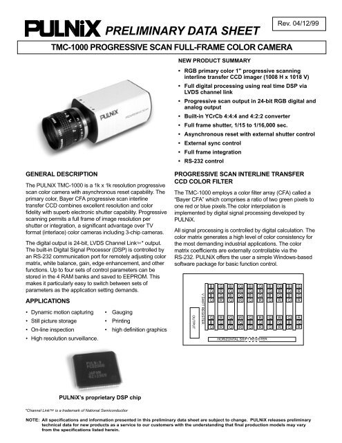
GENERAL DESCRIPTION<br />
The PULNiX TMC-<strong>1000</strong> is a 1k x 1k resolution progressive<br />
scan color camera with asynchronous reset capability. The<br />
primary color, Bayer CFA progressive scan interline<br />
transfer CCD combines excellent resolution and color<br />
fidelity with superb electronic shutter capability. Progressive<br />
scanning permits a full frame of image resolution per<br />
shutter or integration, a significant advantage over TV<br />
format (interlace) color cameras including 3-chip cameras.<br />
The digital output is 24-bit, LVDS Channel Link TM * output.<br />
The built-in Digital Signal Processor (DSP) is controlled by<br />
an RS-232 communication port for remotely adjusting color<br />
matrix, white balance, gain, edge enhancement, and other<br />
functions. Up to four sets of control parameters can be<br />
stored in the 4 RAM banks and saved to EEPROM. This<br />
makes it particularly easy to switch between sets of<br />
parameters as the application setting demands.<br />
APPLICATIONS<br />
• Dynamic motion capturing • Gauging<br />
• Still picture storage • Printing<br />
• On-line inspection • high definition graphics<br />
• High resolution surveillance.<br />
PROGRESSIVE SCAN INTERLINE TRANSFER<br />
CCD COLOR FILTER<br />
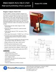
The TMC-<strong>1000</strong> employs a color filter array (CFA) called a<br />
“Bayer CFA” which comprises a ratio of two green pixels to<br />
one red or blue pixels.The color interpolation is<br />
implemented by digital signal processing developed by<br />
PULNiX.<br />
All signal processing is controlled by digital calculation. The<br />
color matrix generates a high level of color consistency for<br />
the most demanding industrial applications. The color<br />
matrix coefficients are externally controllable via the<br />
RS-232. PULNiX offers the user a simple Windows-based<br />
software package for basic function control.<br />
OUTPUT<br />
V SHIFT REGISTER<br />
B<br />
G<br />
B<br />
G<br />
G<br />
B<br />
G<br />
G<br />
R<br />
G<br />
R<br />
R<br />
G<br />
R<br />
B<br />
G<br />
B<br />
G<br />
G<br />
B<br />
G<br />
G B G B G B G<br />
R G R G R G R<br />
G B G B G B G<br />
R G R G R G R<br />
R<br />
G<br />
R<br />
G<br />
B<br />
G<br />
R<br />
G<br />
R<br />
HORIZONTAL SHIFT REGISTER<br />
G<br />
B<br />
G<br />
R<br />
G<br />
R<br />
G<br />
B<br />
G<br />
R<br />
G<br />
R<br />
PULNiX’s proprietary DSP chip<br />
*Channel LinkTM is a trademark of National Semiconductior<br />
NOTE: All specifications and information presented in this <strong>preliminary</strong> <strong>data</strong> <strong>sheet</strong> are subject to change. PULNiX releases <strong>preliminary</strong><br />
technical <strong>data</strong> for new products as a service to our customers with the understanding that final production models may vary<br />
from the specifications listed herein.
TMC-<strong>1000</strong> PRELIMINARY DATA SHEET Rev. 04/12/99<br />
Page 2 of 4<br />
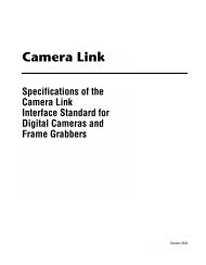
ASYNCHRONOUS RESET<br />
The TMC-<strong>1000</strong> asynchronous reset operates with internal<br />
sync or external HD for phase locking. When VINIT pulse is<br />
applied, it resets the camera’s scanning and purges the<br />
CCD. There are three modes to control the asynchronous<br />
reset and shutter speed:<br />
1. External VINIT with pulse width control. The pulse<br />
width between two pulse edges controls the shutter speed<br />
externally from 1/16,000 sec. to 4 sec.<br />
2. Internal shutter speed with fast mode. The video<br />
signal has no delay from the reset timing . The shutter<br />
speed range is 1/2,000 to 1/16,000 sec.<br />
3. Internal shutter speed with slow mode. The speed<br />
control is variable from 1/15 to 1/1,750 sec. The video signal<br />
starts with internal V reset timing related to shutter speed.<br />
VINIT<br />
VD<br />
SG (TRANSFER GATE)<br />
DISCHARGE PULSES<br />
ASYNC RESET<br />
ELECTRONIC SHUTTER<br />
The TMC-<strong>1000</strong> has a substrate drain type shutter<br />
mechanism which provides a superb picture at various<br />
speeds without smearing. Progressive scanning permits<br />
1016 lines (2 lines less than the imager) of full vertical<br />
resolution per single shutter. The manual shutter speed<br />
control selects the electronic shutter rate of 1/15 to<br />
1/16,000 sec. The user can assign any shutter speed to<br />
any of the preset shutter positions. The factory default<br />
values are as follows:<br />
78<br />
3<br />
6<br />
45<br />
Shutter Control Switch<br />
Manual<br />
Async<br />
0 no shutter no shutter<br />
1 1/60 1/16,000<br />
SHUTTER<br />
2 1/125 1/8,000<br />
0<br />
3 1/250 1/4,000<br />
9<br />
1 2<br />
4 1/500 1/2,000<br />
5 1/1,000 1/1,000<br />
6 1/2,000 1/500<br />
7 1/4,000 1/250<br />
8 1/8,000 1/125<br />
9 1/16,000 Pulse width control<br />
VIDEO<br />
SOFTWARE<br />
NON-INTERLACE OUTPUT<br />
SHUTTER<br />
VIDEO<br />
Fast Mode Operation<br />
NORMAL VIDEO<br />
The asynchronous shutter is activated by selecting async<br />
reset and the shutter speed. The async reset pulse,<br />
VINIT, must be applied to set up the shutter. With VINIT<br />
high (5V), the CCD keeps discharging. With a negative<br />
going pulse to VINIT, the cameras resets and purges the<br />
charge momentarily. Then it starts integrating for the<br />
period of shutter control set either by internal shutter<br />
cotnrol or external pulse width control. Then “0” shutter is<br />
selected in async mode, the camera resets<br />
asynchronously without shutter function; this can be used<br />
for applications requiring strobe lighting.<br />
INTEGRATION<br />
The CCD imager of the TMC-<strong>1000</strong> can be exposed for<br />
longer than 1 frame timing (1/15 sec.). This feature provides<br />
high sensitivity for low light applications. Integration is<br />
achieved by controlling the #11 pin of the 12-pin connector<br />
to Low (GND). Integration also can be achieved by VINIT<br />
pulse width control of the async shutter up to four seconds.
95 6 7 8<br />
3<br />
TMC-<strong>1000</strong> PRELIMINARY DATA SHEET Rev. 04/12/99<br />
Page 3 of 4<br />
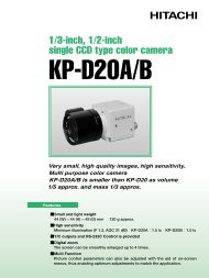
PIN CONFIGURATIONS<br />
REAR PANEL<br />
12-Pin Connector<br />
3<br />
2<br />
1 9<br />
10<br />
11 12<br />
8<br />
7<br />
MAN ASY<br />
SHUTTER<br />
01<br />
2<br />
IWB<br />
RST<br />
IWB G1.0 BANK1<br />
EWB 0.45 BANK2<br />
4<br />
4<br />
5<br />
6<br />
POWER<br />
DIGITAL<br />
RS<br />
232<br />
Pin TMC-<strong>1000</strong> 12P-02 Cable<br />
1 GND Gray<br />
2 +12V DC IN Yellow<br />
3 GND Red Shield<br />
4 N/C Red Coax Signal<br />
5 GND Orange Shield<br />
6 VINIT Orange Coax Shield<br />
7 VD IN Black Coax Signal<br />
8 GND White Shield<br />
9 HDIN White Coax Signal<br />
10 N/C Brown<br />
11 INTEG CONT Blue<br />
12 GND Black Shield<br />
15-Pin SVGA Output Connector<br />
6<br />
11<br />
Pin# Description Pin# Description<br />
1 Red 9 N/C<br />
2 Green 10 GND<br />
3 Blue 11 GND<br />
4 I.D 12 I.D<br />
5 N/C 13 H Sync<br />
6 Red GND 14 V Sync<br />
7 Green GND 15 N/C<br />
8 Blue GND<br />
15-Pin Connector<br />
Airborn: MP2210152432200<br />
1<br />
ANALOG<br />
Shutter Mode Switch<br />
The shutter mode switch selects between manual shutter<br />
mode (MAN) and asynchronous shutter mode (ASY).<br />
Shutter Speed Control Dial<br />
Shutter speed can be selected by switching the shutter dial<br />
to the appropriate setting (0 through 9). The factory default<br />
settings can be used, or each position can have any shutter<br />
speed by assigning a value to the proper register address.<br />
White Balance Control Switches<br />
The IWB/EWB switch selects between Internal White<br />
Balance (IWB) and External White Balance (EWB).<br />
IWB Reset Button<br />
When held down, the IWB Reset Button calibrates the white<br />
balance so that the selected object appears to be white.<br />
After it is released, the camera maintains the last white<br />
balance value.<br />
Gamma Control Switch<br />
The Gamma Control switch selects between gamma 1.0<br />
and gamma 0.45.<br />
Bank Switch<br />
The Bank Switch selects Bank1/Bank2 parameter sets.<br />
Bank3 and Bank4 are selectable only via RS-232C control.<br />
1<br />
9<br />
Pin# Description Pin# Description<br />
1 CH CLK+ 9 CH CLK-<br />
2 CH0+ 10 CH0-<br />
3 CH1+ 11 CH1-<br />
4 CH2+ 12 CH2-<br />
5 CH3+ 13 CH3-<br />
6 D_VINIT+ 14 D_VINIT-<br />
7 D_INTEG+ 15 D_INTEG-<br />
8 GND<br />
Note: CH** : LDVS Channel Link TM output<br />
D_VINIT, D_INTEG: LVDS input for camera control
95 6 7 8<br />
2<br />
3<br />
TMC-<strong>1000</strong> PRELIMINARY DATA SHEET<br />
PRELIMINARY PRODUCT SPECIFICATIONS<br />
Rev.04/12/99<br />
Page 4 of 4<br />
<strong>Image</strong>r<br />
Pixel<br />
Cell size<br />
Scanning<br />
Sync<br />
Data clock output<br />
Resolution<br />
S/N ratio<br />
Min. illumination<br />
Video output<br />
Gamma<br />
Lens mount<br />
Power req.<br />
Operating temp.<br />
Vibration & shock<br />
Size (W x H x L)<br />
Weight<br />
Power cable<br />
Power supply<br />
Functional options<br />
Accessories<br />
1" progressive scanning interline transfer CCD<br />
(Primary RGB color filter)<br />
1008 (H) x 1018 (V)<br />
9.0µm x 9.0µm<br />
Progressive, 1050 lines 15Hz<br />
Internal/external auto switch<br />
HD/VD, 4.0 Vp-p impedance 4.7KΩ<br />
VD = 15Hz ±5%, non-interlace<br />
HD = 15.75KHz ±3%<br />
20.034MHz<br />
Digital: 1006 (H) x 1016 (V)<br />
50dB min., 56dB typical<br />
10.0 lux, f-1.4 (no shutter). Sensitivity: 10µV/e-<br />
Digital: 24-bit LVDS Channel Link TM<br />
Analog: 0.66 Vp-p 75Ω RGB video<br />
0.45 or 1.0 (0.45 std.)<br />
C-mount<br />
12V DC 600mA<br />
-10°C to 50°C<br />
Vibration: 7G, Shock: 70G<br />
51mm x 67mm x 116.5mm (2.01" x 2.64" x 4.58")<br />
374g (13.2 oz.)<br />
12P-02<br />
K25-12V or PD-12<br />
TBD<br />
Digital cable (model# TBD), model CS-232<br />
RS-232 cable with software set, TBD<br />
PHYSICAL DIMENSIONS<br />
67.0 (2.64)<br />
116.5 (4.58)<br />
112.5 (4.43)<br />
PULNiX<br />
51.0<br />
(2.01)<br />
PROGRESSIVE SCAN<br />
7.0 (.28)<br />
2X ø5/50<br />
MAN ASY<br />
IWB<br />
RST<br />
IWB G1.0 BANK1<br />
SHUTTER<br />
EWB 0.45 BANK2<br />
01<br />
4<br />
POWER<br />
DIGITAL<br />
RS<br />
232<br />
22.0<br />
C L<br />
ANALOG<br />
40.0<br />
11.5<br />
For product availability information or technical<br />
assistance contact the Imaging Products Sales Department.<br />
Vision 1<br />
517 E. Aspen St. Tel: 406-585-7225<br />
Bozeman, MT 59715 Fax: 406-586-6041<br />
E-mail:Vision1@Vision1.com<br />
www.vision1.com