A Q-Enhanced LC Bandpass Filter Using CAIRO+ - SoC - LIP6
A Q-Enhanced LC Bandpass Filter Using CAIRO+ - SoC - LIP6
A Q-Enhanced LC Bandpass Filter Using CAIRO+ - SoC - LIP6

Create successful ePaper yourself
Turn your PDF publications into a flip-book with our unique Google optimized e-Paper software.
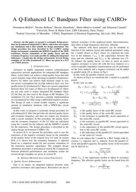
A Q-<strong>Enhanced</strong> <strong>LC</strong> <strong>Bandpass</strong> <strong>Filter</strong> using <strong>CAIRO+</strong><br />
Diomadson Belfort 1 , Nicolas Beilleau 1 , Hassan Aboushady 1 , Marie-Minerve Louërat 1 and Sebastian Catunda 2<br />
1 University Pierre & Marie Curie, <strong>LIP6</strong> Laboratory, Paris, France<br />
2 Federal University of Maranhão - UFMA, Department of Electrical Engineering, São Luís, MA, Brazil<br />
Abstract—In this paper, we present a systematic design procedure<br />
for Q-enhanced integrated <strong>LC</strong> filters, which does not require<br />
any simulations and is thus suitable for design automation. The<br />
design procedure has been described in the <strong>CAIRO+</strong> analog<br />
design environment, containing the BSIM3v3 models of the MOS<br />
transistors. Precise estimations of the quality factor and the<br />
resonance frequency were made possible by adding the integrated<br />
inductance π-model into the design environment. Several design<br />
examples of 2.4 GHz Q-enhanced <strong>LC</strong> filters are given in a 0.13<br />
µm CMOS process.<br />
I. INTRODUCTION<br />
Advances in highly integrated wireless communication<br />
transceivers provide applications for integrated RF bandpass<br />
filters. Active filters can achieve a high quality factor but with<br />
a poor dynamic range when operating at gigahertz frequencies.<br />
Passive <strong>LC</strong> filters can achieve high dynamic range at very<br />
low power consumption but on-chip inductors have very low<br />
quality factor Q. Q-enhanced <strong>LC</strong> filters are a good compromise<br />
between these two types of filters [1]. Q-enhanced <strong>LC</strong> filters<br />
are not only used to realize integrated RF bandpass filters<br />
[2] but they are also used in the design of RF bandpass Σ∆<br />
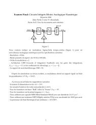
modulators [3], [4]. Fig.1 presents a popular implementation<br />
of a Q-enhanced <strong>LC</strong> filter using a differential negative resistor.<br />
The design of such a circuit usually requires a significant<br />
amount of simulation iterations with a SPICE-like circuit<br />
simulator.<br />
In this work, we propose a systematic design procedure for<br />
a Q-enhanced <strong>LC</strong> filter that provides the desired quality factor<br />
and resonance frequency and does not require any iterations<br />
with a circuit simulator. In this procedure, the quality factor<br />
and the resonance frequency of the <strong>LC</strong> filter are calculated<br />
using the π-model for the inductor and the BSIM3v3 models<br />
for the transistors. The design procedure is described in the<br />
analog design environment <strong>CAIRO+</strong> [5].<br />
In section II-A, we present the procedure used to size the<br />
transistors of the negative resistance based on the estimation<br />
of the quality factor of the original lossy <strong>LC</strong> tank. In section<br />
II-B, it is shown how the resonance frequency is adjusted<br />
based on a empirical model [6] and accurate estimation of<br />
the transistors parasitic capacitance. The complete design<br />
automation procedure is presented in section III. Comparisons<br />
between predicted performances and simulation results for<br />
several design examples are given in section IV.<br />
II. DESIGN METHOD INCLUDING PARASITICS<br />
A. Quality Factor Enhancement<br />
Due to its nature, an integrated inductor presents some<br />
parasitics resistances and capacitances. Resistances are due to<br />
intrinsic resistance of the employed metal, interconnections,<br />
skin effect at high frequencies and lossy substrate.<br />
The inductor with these parasitics can be modeled in<br />
function of the inductor layout and material parameters using<br />
the π-model shown in Fig.2, where R S represent the total<br />
loss in the inductor, C Sub is the capacitance between the<br />
trace and the substrate and R Sub is the substrate loss [7].<br />
To enhance the quality factor, we have to insert an active<br />
negative resistance in series [8] with the lossy inductor or a<br />
series-to-parallel impedance transformation can be performed<br />
on the lossy inductor and a negative resistance can be added<br />
in parallel mode [9] as shown in Fig.3.<br />
In this work the parallel solution was used.<br />
As shown in Fig.4, we transform this π-model to a parallel<br />
model.<br />
In this case we take:<br />
R pl = R S (1 + Q 2 rl)<br />
Q 2 rc<br />
R pc = R Sub (1 + Q 2 rc)<br />
1 + Q 2 rl<br />
C p = C Sub<br />
1 + Q 2 L p = L S<br />
rc<br />
Q 2 rl<br />
R p = R pl //R pc (1)<br />
1<br />
Q rc =<br />
ω 0 R Sub C Sub<br />
Q rl = ω 0L S<br />
R S<br />
where<br />
Q rc is the quality factor of the series-RC circuit;<br />
Q rl is the quality factor of the series-RL circuit;<br />
R pl is the resistance in parallel-RL circuit equivalent to<br />
the series-RL circuit;<br />
R pc is the resistance in parallel-RC circuit equivalent to<br />
the series-RC circuit;<br />
C p is the capacitance in the parallel-RC circuit equivalent<br />
to the series-RC circuit;<br />
L p is the inductance in the parallel-<strong>LC</strong> circuit equivalent<br />
to the series-<strong>LC</strong> circuit.<br />
Then we can replace the π-model by a R<strong>LC</strong> bridge with R p<br />
resistor, C p capacitor and L p inductor. From the parallel resistor<br />
and parallel capacitor, the quality factor of the resonator<br />
can be derived as:<br />
√<br />
C PC + C p<br />
Q 0 = R p (2)<br />
L p<br />
where C PC is the capacitance needed to adjust to resonance<br />
frequency. The effective quality factor can be found from [9]<br />
as<br />
Q 0<br />
Q enh =<br />
(3)<br />
1 − G m0 R p<br />
978-1-4244-5091-6/09/$25.00 ©2009 IEEE 860
Vdd<br />
i in<br />
C Sub<br />
L s<br />
C PC<br />
C PC<br />
C Pc<br />
-1/G m0<br />
R Sub<br />
R s<br />
Iin+<br />
L<br />
Iin-<br />
π-model<br />
Fig. 3.<br />
<strong>LC</strong> filter with Q-enhancement<br />
M1<br />
M2<br />
Vbias<br />
M3<br />
R s L s<br />
R pl<br />
R sub<br />
C sub C p<br />
L p<br />
L p<br />
R p<br />
C p<br />
Fig. 1.<br />
Q-enhanced <strong>LC</strong> filter with differential negative resistance.<br />
R pc<br />
where G m0 is the equivalent transconductance of the differential<br />
negative resistance. So, choosing an appropriate value<br />
for G m0 one can improve the value of the quality factor of<br />
the original lossy <strong>LC</strong> tank from Q 0 to a desired quality factor<br />
Q enh . G m0 is calculated using the approximations:<br />
G m0 = G m − G ds (4)<br />
where G m and G ds are respectively the transconductance<br />
and the output conductance of transistor M 1 Fig.1. In the<br />
<strong>CAIRO+</strong> analog design environment, it is possible to perform<br />
an accurate sizing of a transistor in order to obtain a certain<br />
transconductance G m . Once the dimensions of the transistor<br />
are known, it is also possible to extract accurate value of G ds .<br />
A few iterations are then required to size transistors M 1 and<br />
M 2 according to the required overall G m0 of the differential<br />
negative resistance.<br />
B. Resonance frequency<br />
Fig. 2.<br />
L s<br />
Vdd<br />
R s<br />
Iin + Iin -<br />
C sub<br />
C subM<br />
C sub<br />
R sub<br />
R subM<br />
L s<br />
R s<br />
R sub<br />
Simplified π-model for a differential center-tapped spiral inductor.<br />
In order to calculate C PC the required capacitor value for a<br />
desired resonance frequency ω 0 , the following relation is used:<br />
C par = C p + C dg + C gd + C gs + C ds (5)<br />
C PC = 1<br />
ω0 2L − C par (6)<br />
p<br />
where C par is the total parasitic capacitance, due to the<br />
inductor and the transistors. The MOS parasitic capacitance<br />
Fig. 4.<br />
π-model to parallel model transformation in small signal.<br />
are easily obtained from the transistors BSIM3v3 model. C sub<br />
is extracted from the inductor π-model. Both models are<br />
integrated, available in the <strong>CAIRO+</strong> design environment.<br />
III. DESIGN AUTOMATION AND PERFORMANCE<br />
EVALUATION<br />
A. <strong>CAIRO+</strong> Design Environment<br />
<strong>CAIRO+</strong>, is a framework, developed at the <strong>LIP6</strong> laboratory,<br />
which aims to help analog circuit designers to describe their<br />
design procedure [5]. It provides a library of functions to<br />
describe the netlist template, layout template, specification<br />
template, design space exploration procedure and layout generation.<br />
The general method in <strong>CAIRO+</strong> is to design modules<br />
using devices. Each module has a list of defined parameters,<br />
and one or more procedures. In the case of designing a<br />
bandpass Q-enhanced <strong>LC</strong> filter, the input parameters are: the<br />
desired quality factor, the resonance frequency, the input bias<br />
voltage, and the value of the inductor with its geometrical<br />
parameters. The procedure will calculate and return the sizes<br />
of the transistors, and the value of the capacitor, C PC , of the<br />
resonator.<br />
B. Thermal Noise<br />
The method we have implemented to compute the noise<br />
generated by the filter is described as follows. The noise in<br />
the circuit are presented in Fig. 6. The thermal noise generated<br />
by transistors (In 2 M<br />
) is computed using <strong>CAIRO+</strong> transistor<br />
device, which includes a procedure to compute thermal noise.<br />
The thermal noise of the resonator is computed using the total<br />
parallel resistor as approximated in section II-A so:<br />
I 2 n R<br />
= 4kT<br />
R p<br />
(7)<br />
Considering we have two current noise sources and that they<br />
are uncorrelated we add the two spectral noise density to<br />
obtain the total current noise spectral density at the input. The<br />
861
Vdd<br />
Qenh<br />
Inductance Geometrical Parameters Resonance Frequency<br />
<strong>CAIRO+</strong><br />
Pi Model (Fig. 2)<br />
L,Rs,Csub,Rsub<br />
Parallel Approximation<br />
equ. (1)<br />
Rp<br />
Transconductance Computation<br />
equ. (3) and (4)<br />
Gmo<br />
BSIM3v3<br />
Noise Computation<br />
equ. (7) and (8)<br />
Transistors Sizing<br />
Cpar<br />
Capacitance <strong>Filter</strong> Computation<br />
equ. (6)<br />
Output Noise<br />
Ibias<br />
Transistors Width<br />
Capacitance<br />
Fig. 5.<br />
Q-enhanced <strong>LC</strong> filter design procedure based on Cairo+ design environment including BSIM3v3 models.<br />
Iin+<br />
M1<br />
Vbias<br />
Vdd<br />
R<br />
R<br />
I C L L C<br />
nR I nR<br />
I nM<br />
Fig. 6.<br />
M3<br />
M2<br />
Iin-<br />
Thermal Noise Circuit<br />
equivalent voltage noise can be computed at the output by<br />
multiplying it by the total gain (the total impedance at the<br />
given frequency of the filter) and integrated over the useful<br />
bandwidth (BW) to have the output noise power :<br />
∫<br />
P n = 2 |Z(jω)| 2 (In 2 R<br />
+ In 2 M<br />
)df. (8)<br />
BW<br />
As shown in section IV, the approximation by a parallel<br />
resistor is sufficiently accurate for the quality factor and<br />
resonance frequency computations.<br />
A flowchart of the proposed design procedure, described<br />
in section II-A and II-B, using the <strong>CAIRO+</strong> environment is<br />
presented in Fig.5.<br />
IV. SIMULATION RESULTS<br />
Once the filter is sized, <strong>CAIRO+</strong> can generate the netlist file,<br />
which can be simulated. Simulations results are presented in<br />
the following.<br />
A. Quality factor and resonance frequency<br />
In table I, the calculated transistors dimensions and the<br />
values of the resonator capacitors are listed, for a resonance<br />
I nM<br />
frequency of 2.442 GHz and different quality factors (Q=30,<br />
60, 80). Table II shown the comparison between the performances<br />
calculated by <strong>CAIRO+</strong> and the simulation results.<br />
In Fig.7, simulation results of the impedance versus input<br />
frequency are presented. Effective Q and resonance frequency<br />
can be extracted from Fig. 7. The parameters of the inductance<br />
are: 5 nH inductor (4 turns, 12 µm width and 10 µm spacing,<br />
which give a Q 0 = 15) for a 130 nm technology. The bias<br />
conditions are : V dd = 0.9 V, V bias = 0.3 V. As we can see, the<br />
automatic design procedure is precise for the effective quality<br />
factor and the resonance frequency.<br />
B. Linearity<br />
<strong>Using</strong> this systematic design procedure it is easily possible<br />
to study the importance of the input bias voltage on the<br />
linearity of the filter. Several filters with different input bias<br />
voltages have been designed. Their linearities can be measured<br />
from the output versus input power graphs (V bias is set to<br />
0.3V). In Fig. 8 we show the intermodulation distortion (IM3)<br />
with a two-tone signal. Its also possible to measure the thirdorder<br />
intercept point (IP3) of each filter.<br />
C. Process Variations<br />
The center frequency f 0 of a Q-enhanced <strong>LC</strong> resonator<br />
is a function of the inductance, of the capacitance of the<br />
spiral inductor, number of turns and connected circuitry. The<br />
inductance value is defined by inductor dimensions and is<br />
TABLE I<br />
TRANSISTORS DIMENSIONS AND CAPACITOR VALUE CA<strong>LC</strong>ULATED BY<br />
<strong>CAIRO+</strong> FOR A 130 nm TECHNOLOGY<br />
Q C PC (pF) M 1 /M 2 (W/L) µm M 3 (W/L) µm<br />
30 1.519 1.21/0.13 39.5/0.13<br />
60 1.518 1.93/0.13 60.4/0.13<br />
80 1.517 2.10/0.13 65.8/0.13<br />
862
TABLE II<br />
COMPARISON BETWEEN <strong>CAIRO+</strong> AND SIMULATION RESULTS.<br />
50<br />
Noise Power (Vdd=0.9)<br />
CAIRO<br />
Simulation<br />
f 0 (GHz) Q P n (dBm) f 0 (GHz) Q P n (dBm)<br />
2.442 30 -71.07 2.4422 30.15 -71.50<br />
2.442 60 -66.17 2.4404 60.29 -66.53<br />
2.442 80 -64.72 2.4401 79.10 -64.97<br />
2.442 100 -63.63 2.4397 99.33 -63.77<br />
Pout (dBm)<br />
0<br />
IM3 Power (Vdd=0.9)<br />
Output (Vdd=0.9)<br />
Noise Power (Vdd=0.6)<br />
IM3 Power (Vdd=0.6)<br />
Output (Vdd=0.6)<br />
IP3 (Vdd=0.9)<br />
IP3 (Vdd=0.6)<br />
−50<br />
Noise Floor<br />
6000<br />
Qenh 30<br />
Qenh 60<br />
Qenh 80<br />
Impedance (Ohms)<br />
5000<br />
4000<br />
3000<br />
2000<br />
−100<br />
−100 −90 −80 −70 −60 −50 −40 −30 −20 −10 0<br />
Pin (dBm)<br />
IP3 (Vdd=0.6) IP3 (Vdd=0.9)<br />
Fig. 8. Input output power of fundamental, output noise floor and IM3 versus<br />
Input power for different values of inductor biasing voltage, V dd (Simulation<br />
results)(Fig. 1).<br />
Fig. 7.<br />
1000<br />
2.36 2.38 2.4 2.42 2.44 2.46 2.48 2.5 2.52 2.54<br />
Frequency (Hz)<br />
x 10 9<br />
Total impedance for different values of Q (Simulation results).<br />
the estimated performances of the circuits generated using the<br />
proposed design procedure and the performances measured<br />
from simulation.<br />
relatively unaffected by process variations. On other hand, the<br />
parasitics capacitances has a considerable variation. Since for<br />
R<strong>LC</strong> circuits the sensitivity of the center frequency, f 0 , to the<br />
total capacitance is −0.5 [10], i.e., for a ±10% in capacitance<br />
variation this implies in a ±5% in central frequency shift.<br />
Effects of the process variations on Q enh are generally<br />
more severe than those for f 0 [9], so to identify these effects<br />
the sensitivity of Q enh to G m0 was analysed. Following the<br />
analysis presented in [10], the mathematical definition of<br />
circuit sensitivity is:<br />
{ ∆y<br />
}<br />
Sx y y<br />
= lim = x ∂y<br />
∆x→0 ∆x<br />
y ∂x . (9)<br />
x<br />
<strong>Using</strong> (1) and (3), we get<br />
S Q enh<br />
G m0<br />
= Q enh 1<br />
− 1 =<br />
− 1 (10)<br />
Q 0 1 − G m0 R p<br />
from Eq.10 we can see the high sensitivity of the quality factor<br />
to the process variation for a large Q enh , for example, for a<br />
Q enh of 80, a Q 0 of 15 and considering a Gm 0 variation of<br />
2%, we have a ±8.6% of variation for Q enh . Following this<br />
analysis it is clear that it is necessary to use tuning circuits for<br />
the quality factor, Q enh , and the center frequency, f 0 [11].<br />
V. CONCLUSION<br />
In this paper, we have presented a systematic design procedure<br />
for Q-enhanced <strong>LC</strong> filters using the analog design environment<br />
<strong>CAIRO+</strong>. The procedure is based upon the inductor<br />
π-model and the BSIM3v3 transistor’s model. Several design<br />
examples have been presented to demonstrate the validity of<br />
the approach. Very little difference has been observed between<br />
REFERENCES<br />
[1] D. Li and Y. Tsividis, ”Active <strong>LC</strong> filters on silicon”,IEE Proceedings on<br />
Circuits, Devices and Systems, Vol 147, p 49-56, No.1, February 2000.<br />
[2] S. Li, N. Stanić, K. Soumyanath and Y. Tsividis, ”An Integrated 1.5V 6<br />
GHz Q-enhanced <strong>LC</strong> CMOS <strong>Filter</strong> with Automatic Quality Factor Tuning<br />
using Conductance Reference”,Radio Frequency Integrated Circuits<br />
Symposium, RFIC’05, Vol 147, p 49-56, No.1, February 2000.<br />
[3] N. Beilleau, H. Aboushady, F. Montaudon and A. Cathelin, ”A 1.3V<br />
26mW 3.2GS/s Undersampled <strong>LC</strong> <strong>Bandpass</strong> Sigma-Delta ADC for a SDR<br />
ISM-band Receiver in 130nm CMOS”, IEEE Radio Frequency Integrated<br />
Circuits Symposium, RFIC’09, Boston M.A., U.S.A, June 2009.<br />
[4] Thandri, B. K.; Silva-Martinez, J., ”A 63 dB SNR, 75-mW <strong>Bandpass</strong> RF<br />
Σ∆ ADC at 950 MHz <strong>Using</strong> 3.8-GHz Clock in 0.25-m SiGe BiCMOS<br />
Technology”, IEEE Journal of Solid-State Circuits, Volume: 42, Issue: 2,<br />
pp. 269-279, February 2007.<br />
[5] R. Iskander, L. de Lamarre, A. Kaiser and M.M. Louërat, ”Design Space<br />
Exploration for Analog IPs using <strong>CAIRO+</strong>”,IEEE International Conference<br />
on Electrical Electronic and Computer Engineering, ICEEC’04, p<br />
473-476, Cairo, Egypt, September 2004.<br />
[6] H. Ronkainen, H. Kattelus, E. Tarvainen, T. Ruhisaari, M. Andersson,<br />
P. Kuivalainen, ”IC compatible planar inductors on silicon” Circuits,<br />
Devices and Systems, IEE Proceedings -. 01/03/199703/1997; 144(1):29-<br />
35. ISSN: 1350-2409.<br />
[7] I. J. Bahl, Lumped Elements for RF and Microwave Circuits. Artech<br />
House, 2003<br />
[8] Duncan, R. and Martin, K.W. and Sedra, A.S., ”A Q-enhanced active-<br />
R<strong>LC</strong> bandpass filter”, ”Circuits and Systems II: Analog and Digital Signal<br />
Processing, IEEE Transactions on”,vol.44, no.5, pp 1057-7130, May 1997<br />
[9] W. B Kuhn, Dan Nobbe, D. Kelly and A. W. Osborn : ”Dynamic Range<br />
performance of On-chip RF bandpass filter”, IEEE Transaction on circuit<br />
and system, Vol. 50 , 10 October 2003, p 685-694.<br />
[10] M. Fortunato, Circuit Sensitivity: With Emphasis on Analog <strong>Filter</strong>s,<br />
Texas Instruments Developer Conf. 2007<br />
[11] Li, D.; Tsividis, Y., ”Design techniques for automatically tuned integrated<br />
gigahertz-range active <strong>LC</strong> filters,” Solid-State Circuits, IEEE<br />
Journal of , vol.37, no.8, pp. 967-977, Aug 2002<br />
863