C2059PE MLP - Lube Control
C2059PE MLP - Lube Control
C2059PE MLP - Lube Control

Create successful ePaper yourself
Turn your PDF publications into a flip-book with our unique Google optimized e-Paper software.
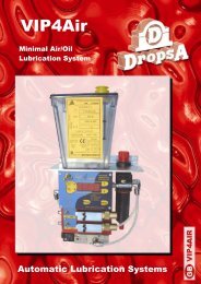
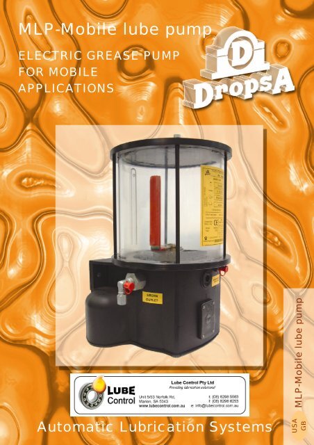
<strong>MLP</strong>-Mobile lube pump<br />
ELECTRIC GREASE PUMP<br />
FOR MOBILE<br />
APPLICATIONS<br />
<strong>MLP</strong>-Mobile lube pump<br />
Automatic Lubrication Systems<br />
USA<br />
GB
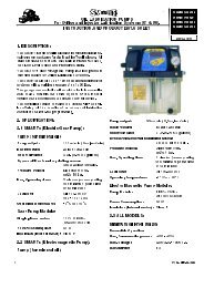
<strong>MLP</strong>-Mobile lube pump<br />
ELECTRIC GREASE PUMP FOR MOBILE<br />
APPLICATIONS.<br />
The <strong>MLP</strong> Electric Grease Lubrication Pump is particularly suited to Mobile lubrication applications<br />
where outdoor installation is necessary.<br />
It can be fitted with up to 3 pump outlets and used with progressive divider systems to construct a<br />
fully automatic mobile lubrication system.<br />
The unit has a choice of three sizes of reservoir and can incorporate a Cycle-Dwell/Cycle or<br />
Dwell-Sensor Timer ! (Dwell-sensor will stop the pump after reading a cycle from a progressive<br />
distributor valve)<br />
Operatine Temperature<br />
Number of Outlets<br />
Grease<br />
Operating Voltage<br />
Power Consumption<br />
GENERAL FEATURES<br />
From - 15°C to + 80°C<br />
( - 59°F to + 176°F )<br />
1 standard, 3 max<br />
NLGI 2 max<br />
12V DC - 24V DC<br />
110V - 230V AC<br />
80 VA<br />
PUMPING ELEMENT<br />
Delivery per min at 20°C c. 2.8 cm³ (cu.inch 0.17)<br />
Outlet Port<br />
1/4" BSP<br />
Incorporated Pressure by-pass<br />
250 bar standard (3675 psi)<br />
Non return valve<br />
Included on outlet.<br />
Work Time (ON Time)<br />
Pause Timer ( OFF Time)<br />
Short-circuit protection<br />
OPTIONAL TIMER MODULE<br />
Min. 20 sec. - max 8 min.<br />
Min. 5 min. - max 12 hr.<br />
Included<br />
Voltage<br />
Reservoir<br />
2 lt<br />
0.44 gals<br />
STANDARD<br />
(NO TIMER)<br />
Reservoir<br />
4 lt<br />
0.88 gals<br />
Reservoir<br />
8 lt<br />
1.76 gals<br />
ORDERING INFORMATION<br />
Reservoir<br />
2 lt<br />
0.44 gals<br />
DWELL-ON<br />
TIMER<br />
Reservoir<br />
4 lt<br />
0.88 gals<br />
Reservoir<br />
8 lt<br />
1.76 gals<br />
DWELL-SENSOR<br />
TIMER<br />
Reservoir<br />
2 lt<br />
0.44 gals<br />
Reservoir<br />
4 lt<br />
0.88 gals<br />
Reservoir<br />
8 lt<br />
1.76 gals<br />
12V 888300 888301 888302 888312 888313 888314 888324 888325 888326<br />
24V 888303 888304 888305 888315 888316 888317 888327 888328 888329<br />
110V 888306 888307 888308 888318 888319 888320 888330 888331 888332<br />
230V 888309 888310 888311 888321 888322 888323 888333 888334 888335<br />
mm – 7.48 inch.<br />
mm – 6.49 inch.<br />
0.35 inch.<br />
mm – 4.5 inch.<br />
mm – 8.1 inch.<br />
Dimensions<br />
2 lt 4 lt 8 lt<br />
Web site:<br />
http://www.dropsa.com<br />
E-mail:<br />
sales@dropsa.com<br />
ITALY<br />
Dropsa SpA<br />
t.(+39) 02-250791<br />
f.(+39) 02-25079767<br />
mm – 8.81 inch.<br />
U.S.A.<br />
Dropsa Corporation<br />
t.(+1) 586-566-1540<br />
f.(+1) 586-566-1541<br />
h<br />
BRAZIL<br />
Dropsa<br />
t.(+55) 011-563-10007<br />
f.(+55) 011-563-19408<br />
mm. 320 340 515<br />
inch. 12.59 13.38 20.27<br />
AUSTRALIA<br />
Dropsa Australia Ltd.<br />
t.(+61) 02-9938-6644<br />
f.(+61) 02-9938-6611<br />
WK 45/02<br />
<strong>C2059PE</strong><br />
SPAIN<br />
Polydrop, S.A.<br />
t.(+34) 93-260-22-50<br />
f.(+34) 93-260-22-51<br />
U.K.<br />
Dropsa (UK) Ltd<br />
t.(+44) 01784-431177<br />
f.(+44) 01784-438598<br />
GERMANY<br />
Dropsa Gmbh<br />
t.(+49) 0211-394-011<br />
f.(+49) 0211-394-013<br />
FRANCE<br />
Dropsa Ame<br />
t.(+33) 01-3993-0033<br />
f.(+33) 01-3986-2636
<strong>MLP</strong> – Mobile <strong>Lube</strong> Pump<br />
Electropump for oil and grease<br />
User and<br />
Maintenance Manual<br />
Warranty information<br />
TABLE OF CONTENTS<br />
1. INTRODUCTION<br />
2. GENERAL DESCRIPTION<br />
3. PRODUCT-MACHINE IDENTIFICATION<br />
4. TECHNICAL CHARACTERISTICS<br />
5. PUMP COMPONENTS<br />
6. UNPACKING AND INSTALLING THE PUMP<br />
7. PUMP OPERATIONS<br />
8. TROUBLESHOOTING<br />
9. MAINTENANCE PROCEDURE<br />
10. DISPOSAL<br />
11. ORDERING INFORMATION<br />
12. DIMENSIONS<br />
13. HANDLING AND TRASPORTATION<br />
14. OPERATING HAZARDS<br />
15. PRECAUTIONS<br />
16. WARRANTY INFORMATION<br />
17. DECLARATION OF COMPLIANCE WITH STANDARDS<br />
18. DROPSA LOCATIONS<br />
Manufacturer<br />
DropsA SpA<br />
Product<br />
<strong>MLP</strong>- Mobile <strong>Lube</strong> Pump<br />
Electropump for oil and grease<br />
Year 2003<br />
Certification<br />
http://www.dropsa.com<br />
Manual drafted in compliance with C2059IE – WK 42/03<br />
EC Directive 98/37, Annex I, paragraph 1.7.4
1. INTRODUCTION<br />
This manual refers to <strong>MLP</strong> pump (Mobile <strong>Lube</strong> Pump).<br />
You can find newer revisions of this document from our Sales Offices, or from our website<br />
http://www.dropsa.com .<br />
The use of the pump referred to in this manual must be entrusted to qualified personnel with a knowledge of<br />
hydraulics and electrical systems.<br />
This user and maintenance manual contains important information on health and safety issues for the personnel.<br />
It is recommended to attentively read this manual and carefully keep it in good condition so that it is always<br />
available to personnel requiring to consult it.<br />
2. GENERAL DESCRIPTION<br />
Centralized lubrication systems significantly reduce the maintenance costs of the equipment on which they are<br />
installed, lowering downtime for maintenance operations and increasing the life of lubricated components.<br />
These systems also enable to reach all the points that require lubrication, including those that are not accessible<br />
to operators.<br />
The aside diagram represents the centralized lubrication system in its basic<br />
configuration.<br />
The system comprises the following units:<br />
A – Electropump with reservoir<br />
B – Main pipe<br />
C – Multiple way distributor<br />
D – Secondary pipes<br />
Once the electropump is commissioned, it supplies a distributor through the main piping coming from the<br />
pumping element. The distributor divides and meters the amount of lubricant among the friction points.<br />
The secondary piping distributes the lubricant to the fittings in the different fixed friction points.<br />
• The serial number of the system must always be quoted when requesting technical information or ordering<br />
spare parts.<br />
<strong>MLP</strong> is a piston pump driven by an eccentric cam which has been designed to operate with a maximum of three<br />
pumping elements.<br />
The housing is a compact monobloc plastic element shaped to offer a full resistance to mechanical stresses.<br />
A roller-shaped system and a grease-scraper enable to eliminate air bubbles from grease, thus ensuring an easy<br />
operation, also at low temperatures.<br />
The worm-geared ratiomotor with helical wheel and DC low voltage, is directly started by the user or through the<br />
control timer setting.
3. PRODUCT – MACHINE IDENTIFICATION<br />
Pump identification label is located on the frontal side of the pump reservoir and contains product serial number,<br />
pressure/input voltage and details of the operating parameters.<br />
4. TECHNICAL CHARACTERISTICS<br />
Operating temperature – 30 °C ÷ + 80 °C ( – 22 °F ÷ + 176 °F )<br />
Number of ports 1 - 2 or 3<br />
Pumping system<br />
Main piping connection<br />
Ø 6 mm (Ø 0.2 in.) piston driven by eccentric cam<br />
Quick fitting for Ø 6 mm (Ø 0.2 in.) piping<br />
Reservoir capacity<br />
2 – 4 - 8 litres (0.44 – 0.88 – 1.76 gallons) with maximum<br />
and minimum level indicators<br />
Mineral lubricant Grease thickness class: up to NLGI 2<br />
Reservoir refilling<br />
System for air-bubbles removal<br />
Maximum pressure<br />
Flowrate * per single outlet<br />
Ratiomotor<br />
Vacuum weight speed<br />
Power supply<br />
Nominal voltage: 12 V DC 1 A<br />
Mechanical protection<br />
<strong>Control</strong> system<br />
24 V DC 0.5 A<br />
110 V AC 0.1 A<br />
220 V AC 0.2 A<br />
IP65<br />
Through A / M10x1 UNI7663 lubricator<br />
Rotating cylinder and grease-scraper<br />
250 ± 50 bar ( 3675 ± 735 psi ) pumping unit built-in safety<br />
valve<br />
~ 2.8 cm 3 /min (~ 0.17 cu.in.)<br />
Worm-geared, with helical wheel and shielded DC low<br />
voltage<br />
22 rpm<br />
12 V DC , 24 V DC , 110/220 V AC - 50 Hz<br />
None / Timer / Timer and Sensor<br />
3
* N.B. The flowrate indicated refers to the following test conditions: grease class NGLI 2, standard ambient<br />
conditions (Temperature +20 °C ( +68 °F) ), pressure 1 atm, counterpressure 100 bar (1470 psi) and nominal<br />
voltage 12 V / 24 V.<br />
CAUTION: Operate the pump only with the voltage indicated on the product label.<br />
5. PUMP COMPONENTS<br />
5.1 PUMPING ELEMENT<br />
1<br />
A<br />
OUTLET No 1 OUTLET No 3<br />
3<br />
2<br />
4<br />
A<br />
The system is usually supplied with a single pumping<br />
element installed on port n° 2.<br />
The figure shows the sequence of operations to be<br />
performed to install a pumping element on port 1 and/or 3.<br />
• Unscrew and remove the seal plug “A” from the outlet<br />
where the pumping unit has to be installed.<br />
• Insert and tighten the pumping element in the selected<br />
configuration “B”.<br />
• Tighten the pumping element with 20 Nmtorque<br />
B<br />
B<br />
CAUTION: the position of the driving cam may hinder pumping element screwing. In this case, it is necessary<br />
to install or insert the pumping element on one of the other ports, paying attention to the correct thread<br />
screwing.<br />
The pumping element is the pump operating-member. It is screwed directly into the<br />
pump housing and driven by means of an eccentric cam. The suction system consists<br />
of a dual free line, while the discharge is provided with an adjustable delivery valve.<br />
The piston contains a safety valve discharging directly into the reservoir, which<br />
immediately discharges the fluid inside the pumping element to avoid excessive<br />
pressure which could potentially damage the system in the event of distributor<br />
blocking.<br />
Pumping element parts are made of high-quality alloy steel, specially treated to<br />
improve wear-resistance characteristics. Furthermore, a special external coating<br />
guarantees excellent resistance to corrosion, tested through salt fog tests.<br />
Technical characteristics:<br />
Boring ……….………………………… Ø 6 mm (Ø 0.23 in.)<br />
Useful stroke<br />
…………………………………<br />
5 mm (0.214 in.)<br />
Flowrate …………………………………. 0.14 cm³ (0.08 cu.in.)<br />
Weight ………………………………………. 0.200 Kg (0.44 lb)<br />
Safety valve ……………………… P max = 250 ± 50 bar (3675 ± 375 psi)<br />
Connection ………………………………… Standard with G1/4” thread<br />
The figure below shows a pumping element with the fitting for the main pipe connection, which is supplied as<br />
standard. The main components are:<br />
2<br />
Pos Part<br />
number<br />
Description<br />
Pumping element with Ø 6 mm<br />
1 888336<br />
1<br />
(Ø 0.23 in.) piston<br />
3<br />
2 888337 Ø22.5x28x1.5<br />
(Ø 0.88 x 1.1 x 0.05 in.) Washer<br />
3 888340 90° fitting G1/4”<br />
4 888341 A M6 UNI7663 Lubricator<br />
5 888342 Plug<br />
4<br />
5<br />
4
Every pumping element is adjusted and tested by the manufacturer.<br />
It is therefore advisable to:<br />
• Avoid to change the set points of the pumping element safety and delivery valves.<br />
• Dropsa Spa shall not be responsible for damages originating from tampering with the safety valve.<br />
• In the event of problems, immediately contact the Customer Service.<br />
5.2 OVER-PRESSURE INDICATOR<br />
The figure below shows a version of the pumping element, which can be supplied as optional and includes an<br />
external signalling system that controls safety valve acting.<br />
The following table lists valve components:<br />
4<br />
1<br />
2<br />
Pos<br />
Part<br />
number<br />
1 888336<br />
Description<br />
Pumping element with Ø 6 mm (Ø 0.23 in.)<br />
piston<br />
2 888337 Ø22.5x28x1.5 (Ø 0.88 x 1.1x 0.05 in.) Washer<br />
3<br />
5<br />
3 888338 G1/4” 3-way shunt<br />
4 888339 Over-pressure indicator 250 bar (3675 psi)<br />
5 888340 90° fitting G1/4”<br />
6 888341 A M6 UNI7663 Lubricator<br />
7 888342 Plug<br />
7<br />
6<br />
During ordinary operating conditions, the external over-pressure<br />
SEGNALATORE<br />
INDICATOR<br />
INDICATOR SEGNALATORE<br />
indicator is at OFF rest (OFF). ON ON<br />
As soon as pumping element outlet pressure reaches 250 bar<br />
(3675 psi), the indicator moves to the signaling position (ON).<br />
After restoring ordinary operating conditions, it is necessary to<br />
verify that the over-pressure indicator is in the OFF position.<br />
P250bar<br />
SCHEMA OPERATING DI FUNZIONAMENTO<br />
DIAGRAM<br />
6. UNPACKING AND INSTALLING THE PUMP<br />
6.1 UNPACKING<br />
Once a suitable location has been found to install the unit remove the pump from the packaging. Check the<br />
pump has not been damaged during transportation or storage. No particular disposal procedures are necessary,<br />
however packing should be disposed of in accordance with regulations that may be in force in your area or state.<br />
6.2 INSTALLING THE PUMP<br />
Allow sufficient space for the installation, leaving minimum 100 mm (3.93 in.) around the pump. Place the pump<br />
at shoulder height to avoid an unnatural posture or possibility of sustaining impacts.<br />
Do not install the pump in aggressive or explosive/inflammable environments or on components subject to<br />
vibration.<br />
- Ensure the fittings and piping are protected from impacts and suitably secured.<br />
6.3 ELECTRICAL WIRING<br />
Operate the pump only with the voltage indicated on the product label.<br />
6.4 HYDRAULIC CONNECTION<br />
5
Connect pump to system by the hydraulic connecting point, located on pump member.<br />
6.5 SETTING OPERATIONS<br />
Pumps without timers do not require any adjustment (time-pressure-flowrate); pumps with timers allow only<br />
pause and working time adjustments.<br />
7. PUMP OPERATION<br />
Centralized lubrication systems are designed for automatic lubrication of the friction points.<br />
• Users are not allowed to make unauthorized changes to an existing system. Modifications must be carried<br />
out or authorized by the manufacturer only or in compliance with him.<br />
• The system should always be used within the operating parameters specified in paragraph 4 (TECHNICAL<br />
CHARACTERISTICS).<br />
• The system must be used only with compatible fluids; see paragraph 15 (PRECAUTIONS).<br />
• For further information, contact Technical Department of Dropsa Spa.<br />
The manufacturer shall not be responsible for damages originating from an improper use or the unauthorized<br />
modification of the system or its components.<br />
Furthermore, the manufacturer shall not be responsible for damages originating from the use of non original<br />
spare parts or parts not certified by the manufacturer, or for damages originating from the use of lubricants<br />
different from those listed.<br />
TOP<br />
Recommendations:<br />
• Do not install pump plunged into liquids or on supports with<br />
high vibrations.<br />
mm<br />
112<br />
(4.4 in.)<br />
• Do not install the pump in locations with explosive or<br />
inflammable mixtures.<br />
• Place the <strong>MLP</strong> electropump in the position shown in the figure.<br />
0°<br />
162 mm<br />
No 2 HOLES Ø9 mm<br />
(0.35 in.)<br />
• Allow 100 mm (3.93 in.) minimum distance from the other<br />
equipments or obstacles which might prevent access to the<br />
pump.<br />
FRONT<br />
0°<br />
• Install the pump ensuring that the refilling lubricator and the<br />
control timer are easily accessible.<br />
• Fix the pump to its support using the Ø 9 mm (Ø 0.35 in.) holes<br />
and the 2 M8 UNI5931 – 8.8 screws.<br />
6
7.1 ELECTRIC WIRING<br />
For electropumps with pause-sensor control Timer, install the Remote <strong>Control</strong> device LED button on the control<br />
board of the machine or vehicle. It is possible to use both the 12/24 V DC and 110/220 V AC remote control devices.<br />
Remote <strong>Control</strong><br />
Harness wiring of remote<br />
control<br />
Remote <strong>Control</strong> control device<br />
wiring diagram<br />
for<br />
LED button<br />
luminous indicator<br />
Mod. A 16 - 1 24 V dc<br />
3) 3) BROWN - Earth - Ground<br />
C NO NC<br />
2) RED / GREEN - Voltage<br />
Keyed for Automotive<br />
Locked<br />
versione<br />
for<br />
automotive version<br />
4) BLACK - Buttom<br />
4) BLACK - Button<br />
5) PURPLE - Luminous indicator<br />
5) PURPLE - LED<br />
The aside figure shows the wiring<br />
electric diagram provided with<br />
LED button. For information on<br />
wiring connections, see the diagram<br />
and choose the version required.<br />
NB: For 110/220 V AC remote control devices, it is recommended the use of a lamp with a voltage over 24 V.<br />
Connect the electropump to the electric system of the vehicle or of the machine on which the lubrication system is<br />
installed.<br />
Electropump 12/24 V DC, without Timer and with Pause/Operation timer.<br />
Power supply is the only connection available.<br />
The above figure shows the power supply/sensor WIRING used for the connection.<br />
A<br />
The wiring is the same used for the<br />
connection of the electropump to the<br />
sensor in the Timer/Sensor versions.<br />
Wiring comes from the pump<br />
assembly marked as A.<br />
Electropump 110/220 V AC, without Timer and Pause/Operation Timer.<br />
The above figure shows the wiring connection diagram.<br />
Even in this case, the wiring comes from the<br />
pump assembly and is supplied with a 600<br />
mm ( 23.6 in.) protective cover.<br />
7
Electropump 12/24 V DC with Pause - Sensor Timer.<br />
Connector A<br />
S<br />
A<br />
1) MARRONE (-)<br />
1) BROWN (-)<br />
2) BLU (+)<br />
2) BLUE (+)<br />
Connector S<br />
The figure shows the wiring diagram.<br />
Power supply/sensor WIRING, coming from pump assembly output S, must be connected to sensor B connector.<br />
Connector coming from pump assembly output A must be connected to the power supply and to the Remote <strong>Control</strong><br />
Device LED button.<br />
Electropump 110/220 V AC with Pause - Sensor Timer.<br />
The diagram shows the electric wiring coming<br />
from the pump assembly outlet A. The<br />
electropump must be connected to power<br />
supply system and to the Remote <strong>Control</strong><br />
device LED button. The wiring is supplied with<br />
approximately 600 mm (23.6 in.) protecting<br />
cover. Power supply/sensor WIRING, coming<br />
from the pump body S output, must be<br />
connected to the sensor, as in the 12/24 V DC<br />
version.<br />
8
ELECTRIC WIRING<br />
DIAGRAM<br />
9
7.2 CONTROLS<br />
The following table describes the command and control devices of centralized lubrication systems with<br />
Pause/Operating timer and Pause/Sensor timer.<br />
The figure shows the devices installed on the Timer.<br />
Pumps without timer are electrically powered by a system which starts the unit. You can find system<br />
commissioning and monitoring instructions among the operation and control instructions of the machine where<br />
the system is installed.<br />
Pos. Type<br />
Description<br />
• It displays the parameters set during the time setting procedure.<br />
1 Display<br />
• LEDs turn on in sequence during ordinary operation.<br />
2 Led This LED turns on when the lubrication system is electrically powered.<br />
It can be actuated by slightly pressing PUSH on the timer access cover.<br />
Pushed during ordinary operation, it starts the set working cycle. At the end of<br />
3 TEST button<br />
the working cycle, the timer returns to the Automatic mode.<br />
Pushed during timer setting, it enables options browsing.<br />
• Pushed for 3 seconds, starts the digital setting procedure.<br />
4 ENTER button • Pushed shortly during the setting mode, enables to change the P (pause)<br />
and L (working) values.<br />
A remote control device is available as optional for systems with Pause - Sensor timer. It must be installed<br />
near to the control panel of the vehicle or the machine where the system is installed.<br />
----- LED<br />
• It turns on when the centralized lubrication system is powered. It remains<br />
on for a few seconds until the timer has completed the initial check and<br />
then turns off.<br />
• It flashes when the pump is started up.<br />
• It turns on when the reservoir is empty or a problem occurs on the system.<br />
• Pushed during ordinary operation, starts a work cycle. At the end of the<br />
working cycle, the timer returns to the Automatic mode.<br />
10
7.3 TIMER SETTING<br />
The following sections summarize the operations needed to be performed for control timer digital setting.<br />
It is useful to remember that in case of power cut, the timer saves the internal data in a long lasting digital<br />
memory. As soon as power is restored, timer reloads the saved data and starts counting the time from the point<br />
and the status its operation had been interrupted.<br />
1- Display<br />
2 - LED<br />
3 - TEST button<br />
4 - ENTER button<br />
N° Operation Effect<br />
01<br />
Unscrew fixing screws “A“ and remove the<br />
cover “B“ to access the timer<br />
This operation gives access to control timer digital<br />
setting.<br />
02 Press ENTER for 3 seconds The display turns on and P (Pause) appears.<br />
03<br />
Press ENTER shortly<br />
The display shows the value set for P parameter.<br />
04 Press TEST to change P value<br />
05 Press ENTER shortly to confirm the setting<br />
Every time the button is pushed, the display sequentially<br />
shows the digits and the letters reported on the pause<br />
time setting table.<br />
The displayed value is stored as current value for P and<br />
the display shows letter P again.<br />
• NB. For versions with Pause-Sensor control timer, skip directly to operation 10, because the only<br />
parameter that can be set is the P (pause time).<br />
The display shows letter L (working time).<br />
06 Press TEST to alternate P and L displays<br />
• NB: Remember that TEST enables to alternate P or<br />
L displays.<br />
07 Press ENTER shortly The display shows the value set for L.<br />
08 Press TEST to change L value<br />
09<br />
Briefly press ENTER to confirm the selected<br />
setting<br />
10 Press ENTER for 3 seconds<br />
11<br />
Remount timer access cover “B” and<br />
retighten screws “A“<br />
Every time the button is pressed, the displays<br />
sequentially shows the digits and the letters reported on<br />
the working time settings table.<br />
The displayed value is stored as current value for L and<br />
the display shows letter L again.<br />
The display turns off and is ready to run with the new set<br />
parameters.<br />
The pump is ready to operate.<br />
11
Time setting tables<br />
• PAUSE: P<br />
Pause time settings<br />
• OPERATION: L<br />
Working time settings<br />
Display Time Display Time<br />
0 5 min 0 20 sec<br />
1 10 min 1 40 sec<br />
2 15 min 2 1 min<br />
3 30 min 3 1.5 min<br />
4 1 h 4 2 min<br />
5 2 h 5 2.5 min<br />
6 3 h 6 3 min<br />
7 4 h 7 3.5 min<br />
8 5 h 8 4 min<br />
9 6 h 9 4.5 min<br />
A 7 h A 5 min<br />
B 8 h B 5.5 min<br />
C 9 h C 6 min<br />
D 10 h D 6.5 min<br />
E 11 h E 7 min<br />
F 12 h F 8 min<br />
NB: working time L can be set only<br />
through the “pause-working” electronic<br />
card.<br />
With pause-sensor electronic card,<br />
The cycle control time is fixed at 10<br />
minutes<br />
CAUTION – Electropump with timer is delivered with the following default settings:<br />
• Pause time = 5h (Display 8)<br />
• Operation time =1 min (Display 2)<br />
7.3.1 TIMER<br />
Located inside the pump casing, in a waterproof housing, it automatically controls the centralized lubrication<br />
system.<br />
Technical specifications for models with Pause/Operation timer, 24 V DC<br />
Operating voltage<br />
Maximum current load<br />
Short circuit limitation<br />
Stand-by current consumption<br />
Cycle current consumption<br />
Working temperature<br />
Storage temperature<br />
Hardware protection<br />
Type of time memory<br />
Memory life<br />
Pause time setting<br />
Working time setting<br />
20 ÷ 30 V DC<br />
5 A<br />
7 A<br />
30 mA<br />
50 mA (motor current excluded)<br />
-25 °C ÷ +70 °C (-13 °F ÷ +158 °F)<br />
-30 °C ÷ +80 °C (-22 °F ÷ +176 °F)<br />
• Overload limitation<br />
• Polarity inversion<br />
• Overheating<br />
• Over voltage (max 45 V DC)<br />
EEPROM<br />
Lifetime of product<br />
From 5 min to 12 hours via digital setting<br />
From 20 sec to 8 min via digital setting<br />
Warning:<br />
• To supply the timer, follow the instructions provided in diagram ELECTRIC WIRING<br />
• Do not supply the timer with voltages over 35 V to prevent operating problems.<br />
12
WORKING - PAUSE/OPERATING CYCLE<br />
The cycle is entirely controlled through the digital timer setting. The system runs a lubrication cycle for the<br />
preset working-time soon after the pause-time interval.<br />
Working time must be set so that the duration of the lubrication cycle is enough to lubricate all the bearing points<br />
connected to it.<br />
To determine the time required to complete a lubrication cycle, disconnect the secondary pipe from any of the<br />
distributor outlets and measure the time interval between two subsequent lubricant deliveries.<br />
For assistance in determining the working time, contact the Customer Service.<br />
SENSOR - PAUSE/OPERATING CYCLE -<br />
The only section of the working cycle controlled by the timer is the pause time setting. After the pre-set time<br />
interval, the system starts lubrication. The proximity sensor, with switch or inductor installed on the progressive<br />
distributor, reads the starting and the end cycle positions and stops the pump automatically.<br />
SENSOR<br />
The sensor, generally fitted on the system, has the same functions of an ordinary button with an outlet acting as<br />
internal contact. This sensor is used with the Pause/Operating Timer.<br />
The working cycle starts by acting the contact of the closed sensor. The pump starts working (lubricating) after<br />
the pre-set pause interval. By operating the distributor, the sensor contact is activated and reads the initial<br />
position of the lubrication cycle. When the distributor operating re-starts, the sensor contact is activated, reads<br />
an end of cycle and stops the pump.<br />
Technical characteristics of the standard sensor :<br />
- Protection grade ……………………… IP68<br />
- Contact ..…………………………………. ON / OFF<br />
- Operating temperature .………………. – 30 °C ÷ + 80 °C (- 22 °F ÷ + 176 °F)<br />
7.4 RESERVOIR REFILLING<br />
paragraph.<br />
The reservoir is refilled through the lubricator “A”. Remove the<br />
lubricator plug and refill the reservoir up to the maximum level<br />
(MAX), by means of a special equipment for pressure<br />
lubrication. For information on lubricant characteristics, see the<br />
following paragraph. During the refilling, verify that the air is<br />
discharged through the air- hole. Ensure that the air-hole,<br />
placed on the reservoir rear side, is not obstructed.<br />
7.4.1 LUBRICANTS<br />
• It is useful to remember that systems manufactured by Dropsa SpA are designed to be used with<br />
lubrications with a maximum grade of NLGI 2<br />
• Use only compatible lubricants with NBR seals<br />
• Dropsa SpA supplies the system components that are already lubricated with NLGI 2 lubricant.<br />
Family description<br />
NLGI<br />
grade<br />
ASTM penetration<br />
at +25°C(+77 °F)<br />
in 1/10 of mm<br />
Fluid greases 000 445 – 475<br />
Semi-fluid greases 00 400 – 430<br />
Semi-fluid greases 0 355 – 385<br />
Mild greases 1 310 – 340<br />
Medium greases 2 265 - 295<br />
The table provides comparative data between NLGI (National<br />
Lubricating Grease Institute) and ASTM (American Society for<br />
Testing and Materials) data only for the values concerning the<br />
systems manufactured by Dropsa SpA.<br />
For further information on technical data and safety measures,<br />
see the Product Safety Sheet (Directive 93/112/EEC) related<br />
to the type of lubricant selected or supplied by the<br />
manufacturer.<br />
13
8. TROUBLESHOOTING<br />
The following diagnostic table highlights the main anomalies which may be encountered, the probable causes<br />
and possible solutions.<br />
If doubt exists or you cannot solve the problem, do not attempt to search for the trouble by<br />
disassembling machine parts but contact the Engineering Department of DROPSA S.p.A.<br />
N Problem Code Possible cause Solution<br />
01.01<br />
Power supply failure<br />
01<br />
02<br />
03<br />
04<br />
Motor does not<br />
operate<br />
Pump does not<br />
deliver lubricant<br />
Pump operates but<br />
does not deliver<br />
lubricant to the<br />
bearing- points<br />
Lubricant reaches<br />
bearing-points in<br />
incorrect quantities<br />
05 LED off<br />
06<br />
07<br />
08<br />
By pushing TEST<br />
button, motor does<br />
not operate<br />
LEDs alternate but the<br />
motor does not run<br />
Pump starts<br />
lubrication but stops<br />
immediately<br />
Verify power supply system, and check<br />
fuse conditions<br />
01.02 Electronic card does not Replace the electronic card<br />
operate<br />
01.03 Ratiomotor does not operate Replace the ratiomotor<br />
02.01<br />
Refill the reservoir with impurity-free<br />
Empty reservoir<br />
lubricant<br />
02.02 Air-bubbles in lubricant Disconnect the main piping from the<br />
pumping connection fitting. Operate the<br />
pump in the manual mode until the fitting<br />
discharges air-bubble free lubricant<br />
02.03 Use of incompatible lubricant Replace the lubricant with a compatible<br />
one<br />
02.04 Obstructed suction pipe-line Disassemble the pumping unit and clear<br />
suction pipe-line<br />
02.05 Pump unit piston worn Replace the pumping unit<br />
02.06 Blocked delivery valve Replace the pumping unit<br />
03.01 Disconnected piping Inspect piping<br />
03.02 Blocked progressive distributor Replace or clear the distributor<br />
04.01 The distributor is not correctly<br />
connected to the bearingpoints<br />
04.02 Incorrect pause time setting Re-set pause time<br />
Compare dosages with system diagram<br />
05.01 Incorrect supply voltage Verify that the supply voltage range is between<br />
20V DC and 30V DC. Then act on the supply<br />
circuit<br />
06.01 Motor is not correctly<br />
connected to timer<br />
06.02 Motor does not correctly<br />
operate<br />
Verify motor connecting wiring to timer.<br />
Then restore the correct connection<br />
Verify the motor neither is short-circuited<br />
nor it absorbs a current over 7A. Replace<br />
the ratiomotor<br />
07.01 Faulty motor Contact the Customer Service<br />
08.01 Faulty motor or high output<br />
consumption<br />
Allow the pump being cooled for a few minutes<br />
and try again. If the problem still continues,<br />
contact the Customer Service<br />
14
9. MAINTENANCE PROCEDURE<br />
9.1 MAINTENANCE OPERATION<br />
This paragraph provides essential information to allow maintenance staff to perform ordinary maintenance in<br />
safety.<br />
Before performing any maintenance procedure, operators should remember to:<br />
• Verify<br />
• Disconnect<br />
• Open<br />
• Adopt<br />
that the system is stopped<br />
the electropump from the power supply<br />
the selector contact switch placed on the upper side of the electric cabinet<br />
all the protective measures in accordance with the accident prevention, especially those<br />
necessary to warn that the system is in maintenance.<br />
9.2 SCHEDULED MAINTENANCE<br />
Due to components simplicity of design, sturdy construction and reliability, Dropsa SpA expects a limited<br />
number of inspections and scheduled maintenance interventions.<br />
The following table lists the checks that have to be performed periodically, along with the frequency and type of<br />
interventions that the serviceman must perform to guarantee the efficiency of the system for a long time.<br />
CHECK RECURRENCE INTERVENTION<br />
Components tightening After the first 500 hours<br />
Check that all components have been correctly<br />
tightened<br />
Piping fixing<br />
Check snap-on connections<br />
After the first 500 hours<br />
Check that machine parts have been fixed<br />
Every 1500 hours<br />
properly<br />
Electropump functioning Every 6 months<br />
Verify electropump functioning by pushing the<br />
TEST button<br />
Reservoir level As required Refill the reservoir<br />
Refilling filter<br />
Every 2 refills<br />
Check and replace the filter, if necessary (see the<br />
following paragraph)<br />
9.3 FILTER REPLACEMENT<br />
C B A<br />
For refilling filter maintenance, remove plug“ A”, lubricator“ B” and filter “C”.<br />
Inspect and clean the filter with compressed air, when required.<br />
If the filter is still dirty after being cleaned, replace it.<br />
Remount filter “C”, lubricator “B” and plug “A”.<br />
Tighten lubricator “B” with torque 6Nm maximum.<br />
10. DISPOSAL<br />
During maintenance or disposal of the machine care should be taken to properly dispose of environmentally<br />
sensitive items such as oils or other lubricants. Refer to local regulations in force in your area.<br />
When disposing of this unit, it is important to ensure that the identification label and all the other relative<br />
documents are also destroyed.<br />
15
11. ORDERING INFORMATION<br />
Reservoir<br />
Voltage<br />
Electropump without timer<br />
2 lt<br />
0.44 galls<br />
4 lt<br />
0.88 galls<br />
8 lt<br />
1.76 galls<br />
Electropump with pause/working<br />
timer<br />
2 lt<br />
0.44 galls<br />
4 lt<br />
0.88 galls<br />
8 lt<br />
1.76 galls<br />
Electropump with pause/sensor<br />
timer<br />
2 lt<br />
0.44 galls<br />
4 lt<br />
0.88 galls<br />
8 lt<br />
1.76 galls<br />
12 V 888300 888301 888302 888312 888313 888314 888324 888325 888326<br />
24 V 888303 888304 888305 888315 888316 888317 888327 888328 888329<br />
110 V 888306 888307 888308 888318 888319 888320 888330 888331 888332<br />
230 V 888309 888310 888311 888321 888322 888323 888333 888334 888335<br />
12. DIMENSIONS<br />
The following table lists, for each model, the pump vacuum weight in the standard configuration, i.e. with a single<br />
pumping element installed.<br />
The following figure shows the maximum overall dimensions expressed in mm (in.):<br />
To facilitate maintenance allow minimum100 mm (3.93 in.) of access on all sides.<br />
Version<br />
Vacuum weight with the pumping element<br />
installed<br />
Reservoir capacity 2 litres (0.44 galls) 3.3 kg (7.3 lb)<br />
Reservoir capacity 4 litres (0.88 galls) 4.8 kg (10.6 lb)<br />
Reservoir capacity 8 litres (1.76 galls) 5.5 kg (12.1 lb)<br />
16
13. HANDLING AND TRANSPORTATION<br />
Prior to shipping, <strong>MLP</strong> pumps are carefully packed in cardboard boxes. During transportation and storage,<br />
always maintain the pump the right way up as indicated on the box.<br />
On receipt check that the packaging has not been damaged and store the pump in a dry place.<br />
14. OPERATING HAZARDS<br />
SAFETY WARNINGS<br />
• An improper use of the centralized lubrication system may cause damages due to an excessive or<br />
inadequate lubrication of the points to which it is connected.<br />
• It is always necessary to comply with the accident prevention laws and the environmental regulations in<br />
force in the area where the centralized lubrication system is used.<br />
It is necessary to read and understand the possible hazards and risks involved when using a lubrication pump.<br />
The operator must fully understand the hazards explained in this manual.<br />
Power supply<br />
Any type of intervention must not be carried out before unplugging of the machine from the power supply. Make<br />
sure that no one can start it up again during the intervention.<br />
All the installed electric and electronic equipment, reservoirs and basic components must be grounded.<br />
Flammability<br />
The lubricant generally used in lubrication systems is not normally flammable. However, it is advised to avoid<br />
contact with extremely hot substances or naked flames.<br />
Pressure<br />
Prior to any intervention, check the absence of residual pressure in any branch of the lubricant circuit as it may<br />
cause oil sprays when disassembling components or fittings.<br />
Noise<br />
Pump does not produce excessive noise, less than 70 dB(A) .<br />
15. PRECAUTIONS<br />
Verification of compliance with essential safety requirements and machine Directive dispositions has been<br />
carried out filling in checking lists provided and contained in the technical file.<br />
Dropsa used three kinds of checking list:<br />
• List of hazards (according to the EN 1050 as it refers to EN 292);<br />
• Enforcement of the essential safety requests (machine Directive – annex 1, part 1);<br />
• Electric safety requirements (EN 60204-1)<br />
The following is a list of dangers which have not been fully eliminated but which are considered<br />
acceptable:<br />
♦ During assembly or maintenance oil squirts at low pressure are possible. (For this reason suitable<br />
personal protective clothing must be worn and appropriate protective measures must be taken<br />
during these operations).<br />
♦ Contact with oil -> see the requirements for the use of suitable individual protective measures<br />
♦ use of incompatible lubricant -> fluid characteristics are shown on the pump and in the manual (in<br />
case of doubt contact Dropsa S.p.A. Eng. Dept.).<br />
♦ Protection against direct and indirect contact must be provided by the user.<br />
♦ as the pump must always be functioning, it is necessary to control the electrical connections so that,<br />
in the case of power failure, customer’s machine is restarted only by means of a reset, while<br />
lubrication pump can restart automatically.<br />
♦ it is recommended to reseal the retailer any time the reservoir is uncovered for maintenance.<br />
♦ Carefully avoid to clear the pump using alcohol.<br />
17
INCOMPATIBLE FLUIDS<br />
Fluid<br />
Danger<br />
Lubricants containing abrasive components<br />
Premature wear of pump<br />
Lubricants containing silicon<br />
Pump failure<br />
Petrol – solvents – inflammable liquids<br />
Fire – explosion –seal damage<br />
Corrosive products<br />
Pump damage - danger to persons<br />
Water<br />
Pump oxidization<br />
Food Products<br />
Contamination of the product<br />
15. WARRANTY<br />
All products manufactured and marketed by Dropsa are warranted to be free of defects in material or<br />
workmanship for a period of at least 12 months from date of delivery.<br />
Extended warranty coverage applies as follows:<br />
Complete system installation by Dropsa: 24 Months<br />
All other components: 12 months from date of installation; if installed 6 months or more after ship date, warranty<br />
shall be maximum of 18 months from ship date.<br />
If a fault develops, notify us giving a complete description:<br />
fault<br />
product code<br />
test record number where available (format xxxxxx-xxxxxx)<br />
date of delivery<br />
date of installation<br />
the operating conditions of the subject product(s).<br />
We will subsequently review this information and, at our option, supply you with technical service or shipping<br />
instruction and returned materials authorization number (RMA) which will have instructions on how to prepare<br />
the product for return.<br />
Upon prepaid receipt of subject product to an authorized Dropsa Sales & Service location, we will then either<br />
repair or replace such product(s), at out option. If the warranty is not run out yet, we will perform such necessary<br />
product repairs or replace such product(s) at our expense.<br />
Dropsa reserves the right to charge an administration fee (logistic, checking etc.) if the product(s) returned are<br />
found to be not defective.<br />
This limited warranty does not cover any products, damages or injuries resulting from misuse, neglect, normal<br />
expected wear, chemically caused corrosion, improper installation or operation contrary to factory<br />
recommendation. Nor does it cover equipment that has been modified, tampered with or altered without<br />
authorization.<br />
Consumables and perishable products are excluded from this or any other warranty.<br />
No other extended liabilities are stated or implied and this warranty in no event covers incidental or<br />
consequential damages, injuries or costs resulting from any such defective product(s).<br />
The use of Dropsa product(s) implies the acceptance of our warranty conditions. Modifications to our standard<br />
warranty must be in made in writing and approved by Dropsa.<br />
18
17. DECLARATION OF COMPLIANCE WITH CE STANDARDS<br />
Manufacturer:<br />
DROPSA SpA<br />
Via B. Croce, 1 - 20090 Vimodrone (MI)<br />
Address<br />
02 – 250.791<br />
Telephone<br />
states, by the terms of Directive 89/392/EEC, Annex II, paragraph B, that:<br />
The Machine:<br />
E-PUMP- Mobile lube pump<br />
• Has been designed to be integrated in a machine that complies with the requirements of Directive 89/392/EEC.<br />
• Is compliant with the requirements of Directive 89/392/EEC and subsequent amendments (Directives 91/368/EEC,<br />
93/44/EEC, 93/68/EEC).<br />
• Is compliant with the requirements of the EMC Directive 89/336/EEC and with Directive 92/31/EEC “Electromagnetic<br />
compatibility", as indicated in Directive 95/54/EEC “Measurement of irradiated electromagnetic emissions”.<br />
Furthermore, the manufacturer states that the unit can be operated only if the machine on which it is installed has been<br />
identified and found compliant with the requirements of Directive 89/392/EEC.<br />
TECHNICAL DIRECTOR<br />
DROPSA SpA<br />
Company<br />
Signature<br />
W. Divisi<br />
Name<br />
January 2003<br />
Date<br />
It is useful to remember that the Declaration of Conformity is valid only if:<br />
• The indications, safety warnings and instructions given in the operation and maintenance manual are observed.<br />
• The system is used in accordance with the instructions provided by the manufacturer.<br />
• Adjustment operations are carried out by authorized, trained and qualified personnel.<br />
• Maintenance operations are carried out by qualified and authorized technicians.<br />
Failure to comply with the requirements listed in the Certificate of Conformity shall automatically invalidate the warranty.<br />
19
18. DROPSA LOCATIONS<br />
Dropsa USA Inc.<br />
50679 Wing Drive<br />
Utica, Michigan 48315, USA<br />
Tel: (+1) 586-566-1540<br />
Fax: (+1) 586-566-1541<br />
E-mail: salesusa@dropsa.com<br />
Dropsa France<br />
23, Av. des. Morillons<br />
Z.I. des Doucettes<br />
91140 - Garges Les Gonesse<br />
Tel: (+33) 01 39 93 00 33<br />
Fax: (+33) 01 39 86 26 36<br />
E-mail: sales@dropsa.com<br />
Dropsa (UK) Ltd<br />
Unit 6, Egham Business Village,<br />
Egham,Surrey,TW20 8RB<br />
Tel: (+44) 01784 - 431177<br />
Fax: (+44) 01784 - 438598<br />
E-mail: salesuk@dropsa.com<br />
Dropsa do Brazil<br />
Rua Sobralia 171 Santo Amaro,<br />
Sao Paulo<br />
Tel: (+55) 011-5631-0007<br />
Fax: (+55) 011-5631-9408<br />
E-mail: salesbr@dropsa.com<br />
Dropsa S.p.A.<br />
Via B. Croce,1<br />
20090 Vimodrone (MI) Italy.<br />
Tel: (+39) 02.250.79.1<br />
Fax: (+39) 02.250.79.767<br />
E-mail: sales@dropsa.it (Export)<br />
E-mail: vendite@dropsa.it (National)<br />
Polydrop S.A.<br />
Av. Fabregada 26 - Pje Est.2<br />
08907 L'Hospitalet de LLobregat<br />
Barcelona, Spain<br />
Tel: (+34) 93 260 22 50<br />
Fax: (+34) 93 260 22 51<br />
E-mail: sales@dropsa.it<br />
Dropsa Gmbh<br />
Volmerswerther Strasse 80<br />
40221 Dusseldorf 1, Germany<br />
Tel: (+49) 0211-394-011<br />
Fax:(+49) 0211-394-013<br />
E-mail: sales@dropsa.de<br />
Dropsa Australia Pty.<br />
C20/148 Old Pittwater Road<br />
Brookvale NSW 2100<br />
Tel: (+61) 299 386 644<br />
Fax: (+61) 299 386 611<br />
E-mail: sales@dropsa.com<br />
Web site: http://www.dropsa.com - E-mail: sales@dropsa.com<br />
20