Pdf - Cornell High Energy Synchrotron Source - Cornell University
Pdf - Cornell High Energy Synchrotron Source - Cornell University
Pdf - Cornell High Energy Synchrotron Source - Cornell University

You also want an ePaper? Increase the reach of your titles
YUMPU automatically turns print PDFs into web optimized ePapers that Google loves.
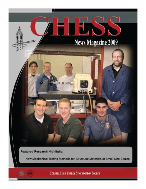
On the Cover:<br />
New testing for small size scales<br />
Professor Matthew Miller and his group from the Sibley School<br />
of Mechanical and Aerospace Engineering standing in front of the load<br />
frame / diffractometer system located in Rhodes Hall, <strong>Cornell</strong> <strong>University</strong>.<br />
Back row (left to right): Michael Ross, Kevin McNelis, and Jay Schuren.<br />
Front row (left to right): Jon Acquaviva, Zachary Peeples, Ben Oswald,<br />
and Professor Miller. The system was designed and built for their high<br />
energy diffraction work at CHESS - Complete article on page 37.<br />
Contents<br />
Staff in Focus<br />
John Kopsa<br />
from the Staff<br />
Welcome the new<br />
Chae Un Kim<br />
Facility Upgrades<br />
Chris Conolly<br />
Facility <strong>High</strong>lights<br />
Education & Outreach<br />
Lora Hine<br />
MacCHESS Advances<br />
Marian Szebenyi<br />
2 CHESS Director’s Report<br />
Sol Gruner<br />
3 G-line Director’s Report<br />
Joel Brock<br />
4 MacCHESS Director’s Report<br />
Marian Szebenyi<br />
6 CHESS Assistant Director’s Report<br />
Ernie Fontes<br />
8 User and Student <strong>High</strong>lights<br />
Ernie Fontes and Kathy Dedrick<br />
11 Staff in Focus<br />
Laura Houghton<br />
13 Facility Upgrades, Networking and Computing<br />
Chris Conolly<br />
17 C-line Upgrades and New Capabilities<br />
Ernie Fontes and Ken Finkelstein<br />
19 D-line Upgrades and New Science Capabilities<br />
Ernie Fontes and Detlef Smilgies<br />
22 Education & Outreach<br />
Lora Hine<br />
25 MacCHESS Advances: Microcrystallography & More<br />
Marian Szebenyi<br />
27 Station F3<br />
Ulrich Englich<br />
28 XPaXS: Improved Data Acquisition & Real-Time Analysis at CHESS<br />
Darren Dale<br />
30 CHESS <strong>High</strong>-pressure B1/B2 Update<br />
Zhongwu Wang<br />
31 The <strong>Cornell</strong> <strong>Energy</strong> Recovery Linac:<br />
update on a future source of coherent hard x-rays<br />
Don Bilderback, Bruce Dunham, Georg Hoffstaetter,<br />
Alexander Temnykh, and Sol Gruner<br />
CHESS News Magazine 2009
The <strong>Cornell</strong> <strong>High</strong> <strong>Energy</strong> <strong>Synchrotron</strong> <strong>Source</strong> (CHESS)...<br />
CHESS - <strong>Cornell</strong> <strong>University</strong><br />
Rt 366 & Pine Tree Road<br />
Ithaca, NY 14853<br />
phone: 607-255-7163<br />
fax: 607-255-9001<br />
...is a user-oriented National Facility to provide state-of-the-art synchrotron radiation facilities to the<br />
scientific community.<br />
Supported by grants from the Division of Materials Research of the National Science Foundation, CHESS<br />
encompasses a multifaceted research and development program which is partly in-house and partly<br />
collaborative, with a wide spectrum of experimental groups from Universities, National Laboratories<br />
and Industry.<br />
Research <strong>High</strong>lights<br />
Mechanical Testing<br />
Matt Miller<br />
Citrine Structure<br />
Sol Gruner<br />
Super BioSAXS<br />
Richard Gillilan<br />
Topography<br />
Richard Jones<br />
Nanoparticles<br />
John Hart<br />
37 New Mechanical Testing Methods for Structural<br />
Materials at Small Size Scales<br />
Matthew P. Miller<br />
43 Alteration of Citrine Structure by Hydrostatic Pressure<br />
Sol Gruner, Buz Barstow, Nozomi Ando,<br />
and Chae Un Kim<br />
45 Putting Color into Surface Diffraction<br />
Detlef Smilgies<br />
48 Self-Assembled Nano-Checkered Thin Films Studied<br />
by Reciprocal Space Mapping at CHESS<br />
Sean O’Malley, Peter Bonanno, Keun hyuk Ahn,<br />
Andrei Sirenko, Alex Kazimirov, Soon-Yong Park,<br />
Yoichi Horibe, and Sang-Wook Cheong<br />
50 Structures from Solutions: Biomolecular Small-Angle<br />
Solution Scattering at MacCHESS<br />
Richard Gillilan<br />
54 Development of X-ray Pixel Array Detectors<br />
Sol Gruner<br />
56 Exploring New Physics of Nanoparticle Supercrystals<br />
by <strong>High</strong> Pressure Small Angle X-ray Diffraction<br />
Zhongwu Wang, Ken Finkelstein,<br />
and Detlef Smilgies<br />
58 Topography of Diamonds at CHESS helps Nuclear<br />
Physics Program at JLAB<br />
Richard Jones, Franz Klein, and Ken Finkelstein<br />
60 Nanoparticle-block Copolymer<br />
Ulrich Wiesner, Laura Houghton, and Sol Gruner<br />
61 Heat-bump Measurements at CHESS<br />
A2 Wiggler Beam<br />
Peter Revesz, Alex Kazimirov, Ivan Bazarov,<br />
Jim Savino, Emmett Windisch, and Christopher<br />
MacGahan<br />
63 Advances in X-ray Microfocusing with Monocapillary<br />
Optics at CHESS<br />
Sterling Cornaby, Thomas Szebenyi,<br />
Heung-Soo Lee, and Don Bilderback<br />
67 Watching Carbon Nanotube Forest Growth<br />
using X-rays<br />
Eric Meshot, Mostafa Bedewy, Sameh Tawfick,<br />
K. Anne Juggernauth, Eric Verploegen, Yongyi<br />
Zhang, Michael De Volder, and John Hart<br />
71 Phase Behavior of Water inside Protein Crystals<br />
Chae Un Kim, Buz Barstow, Mark Tate,<br />
and Sol Gruner<br />
Other Information<br />
The <strong>Cornell</strong> <strong>High</strong> <strong>Energy</strong> <strong>Synchrotron</strong> <strong>Source</strong> is<br />
supported by the National Science Foundation and the<br />
National Institutes of Health/National Institute of<br />
General Medical Sciences under grant DMR 0225180.<br />
MacCHESS is supported by NIH 5 P41 RR001646-24.<br />
Editor: Laura Houghton, lab49@cornell.edu<br />
Co-editor: Marian Szebenyi, dms35@cornell.edu<br />
Layout and design:<br />
Laura Houghton - CHESS, <strong>Cornell</strong> <strong>University</strong><br />
Special thank you to David Schuller<br />
CHESS News Magazine 2009 Page 1
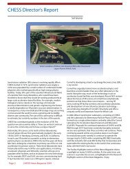
CHESS Director’s Report<br />
Sol Gruner<br />
Artist’s rendition of Wilson Lab showing CESR under the present<br />
Upper Alumni Athletic field.<br />
<strong>Synchrotron</strong> radiation (SR) science is evolving rapidly. When<br />
CHESS started in 1979, synchrotron radiation was largely a<br />
niche area populated by a small number of condensed matter<br />
physicists who worked parasitically at high energy physics<br />
facilities. Today, SR is part of the essential infrastructural fabric<br />
of scientists from many disciplines, who would have been<br />
shocked to know that they would be working productively at<br />
large-scale accelerator-based facilities. For example, modern<br />
biological science stands on the two legs of molecular<br />
structural determination and genetic engineering; the former<br />
is totally dependent on SR protein structure determination. In<br />
consequence, many new dedicated SR storage rings are coming<br />
on-line around the world to serve a growing and incredibly<br />
diverse user community. The size of this community is difficult<br />
to estimate, but certainly numbers in the tens of thousands.<br />
CHESS has contributed greatly to the evolution of SR. The<br />
question we ask ourselves daily is: “How can we best continue<br />
to serve the community and to have a unique impact”<br />
Historically, SR science cut its teeth at three laboratories:<br />
<strong>Cornell</strong> (where SR was first systematically studied in the early<br />
1950’s), DESY in Hamburg, Germany, and SLAC in California.<br />
In each case SR started as a parasitic activity to elementary<br />
particle physics accelerators. Within the last few years all three<br />
labs have undergone a transition to primary use of the on-site<br />
accelerators for photon science. These three laboratories have<br />
historically led the way in SR for user applications, in training<br />
accelerator physicists and SR facility scientists who go on to<br />
populate other facilities, and as incubators for new technology.<br />
So, for example, DESY and SLAC are now commissioning hard<br />
X-ray Free Electron Lasers (as is SPring-8 in Japan), whereas<br />
<strong>Cornell</strong> is developing a hard x-ray <strong>Energy</strong> Recovery Linac (ERL)<br />
x-ray source.<br />
<strong>Cornell</strong> has arguably trained more accelerator physics and<br />
beamline scientist leaders than any other laboratory in the<br />
world. Along the way, much of the technology in use at<br />
accelerator-based facilities was developed. Recent NSF reviews<br />
about the future of SR science at <strong>Cornell</strong> have emphatically<br />
pointed out that these three core missions -- serving SR<br />
users, training SR facility scientists and accelerator physicists,<br />
and development of new SR and accelerator technology –<br />
are continuing strengths of <strong>Cornell</strong>’s SR activity and offer a<br />
uniquely useful and important future for Wilson Lab.<br />
In 2006, Wilson <strong>Synchrotron</strong> Laboratory, consisting of CHESS<br />
and the Laboratory for Elementary-Particle Physics (LEPP), was<br />
formed into a single administrative umbrella called the <strong>Cornell</strong><br />
Laboratory for Accelerator-based ScienceS and Education<br />
(CLASSE). Proposals for continued operation of CHESS and ERL<br />
R&D through 2014 have been extremely favorably reviewed;<br />
we are very optimistic that these activities will continue. These<br />
continuing awards will be very positive steps in our hoped<br />
for evolutionary path, namely, to continue to operate the<br />
storage ring for CHESS while completing ERL R&D. Eventually<br />
we’d like to build a full-scale ERL facility that incorporates and<br />
supersedes the existing facility as the world’s first continuousduty,<br />
coherent hard x-ray source.<br />
The Facility <strong>High</strong>lights section of this News Magazine shines<br />
a spotlight on many CLASSE activities. At the same time, user<br />
science is as productive as ever, as highlighted in the Research<br />
<strong>High</strong>lights section of the News Magazine. Enjoy.<br />
Page 2 CHESS News Magazine 2009
G-Line Director’s Report<br />
Joel Brock<br />
G-line has had another banner year, both in terms of the<br />
exciting forefront science that has been accomplished and in<br />
the truly excellent graduate students who have been trained<br />
and performed their research there. For example, the <strong>Cornell</strong><br />
Center for Materials Research’s Interdisciplinary Research<br />
Group studying the growth of thin-films of chemically<br />
complex materials is operating both pulsed laser and<br />
supersonic molecular beam (SMB) deposition systems in the<br />
G3 experimental station. They are using them to perform in<br />
situ, real-time x-ray structural studies of the growth processes<br />
occurring during deposition. These research programs involve<br />
several <strong>Cornell</strong> faculty research groups (faculty, post-docs,<br />
graduate students, and undergrads) and several of the CHESS<br />
staff scientists. The program studying the growth of thin<br />
films of organic semiconductors via SMB deposition provides<br />
an excellent example of the value of both in situ studies and<br />
the immersion of post-docs and graduate students in the<br />
G-line facility. Supervised by Professors George Malarias<br />
(Materials Science), James Engstrom (Chemical Engineering),<br />
Joel Brock (Applied Physics) and Arthur Woll (CHESS/G-line),<br />
post-doctoral research associates Aram Amassian and Sukwon<br />
Hong and graduate students Vladimir Pozdin, Tushar Desai,<br />
and John Ferguson deposited thin films of pentacene onto<br />
SiO 2<br />
a gate dielectric, treated with hexamethyldisilazane<br />
(HMDS) and fluorinated octyltrichlorosilane (FOTS). The<br />
morphology of pristine, as-deposited thin films was<br />
determined during growth by in situ real-time X-ray reflectivity<br />
and was measured again, ex situ, by atomic force microscopy<br />
(AFM) following aging at room temperature in vacuum, in<br />
N 2<br />
atmosphere, and in ambient air. The films deposited on<br />
HMDS and FOTS undergo significant reorganization under<br />
vacuum or in N 2<br />
atmosphere1. The changes observed indicate<br />
a de-wetting behavior. This work highlights the propensity of<br />
small-molecule thin films to undergo significant molecularscale<br />
reorganization at room temperature when kept in<br />
vacuum or in N 2<br />
atmosphere after deposition, and provides<br />
a cautionary note to anyone investigating the behavior of<br />
organic electronic devices and the relationship of ex situ<br />
studies to the initial growth of ultra-thin molecular films.<br />
The SMB deposition system was designed and built over<br />
the past several years by graduate students in the Engstrom<br />
research group. The data collection was a collaboration led<br />
by Drs. Amassian and Hong with intensive involvement by<br />
the graduate students. Arthur Woll’s development of the<br />
analytical tools necessary to extract reliable coverage data<br />
from the time-dependent x-ray reflectivity data was crucial to<br />
the success of this project. Dr. Amassian has recently accepted<br />
a faculty position at the brand new King Abdullah <strong>University</strong> of<br />
Science and Technology (KAUST) but continues to collaborate<br />
with G-line through the KAUST center at <strong>Cornell</strong>.<br />
References<br />
1. A. Amassian, V.A. Pozdin, T.V. Desai, S. Hong, A.R. Woll, J.D.<br />
Ferguson, J.D. Brock, G.G. Malliaras, and J.R. Engstrom;<br />
“Post-deposition Reorganization of Pentacene Films<br />
Deposited on Low-<strong>Energy</strong> Surfaces”, Journal of Materials<br />
Chemistry 19, 5580-5592 (2009)<br />
AFM images (3×3 μm 2 ) obtained ex situ<br />
from ~8 ML pentacene thin films deposited<br />
from a supersonic source (E i<br />
= 2.5 eV) on<br />
(a) bare SiO 2<br />
and on SiO 2<br />
treated with (b)<br />
HMDS and (c) FOTS. The continuous (color<br />
filled) curves were calculated directly from<br />
the AFM images. The (hollow) bars were<br />
calculated from the X-ray measurements.<br />
(a) and (b) were obtained after aging 12<br />
hours in vacuum and 30 days in air, (c) was<br />
obtained after 6 hours in vacuum and 60<br />
days in air. Figure from Ref. [1].<br />
CHESS News Magazine 2009 Page 3
MacCHESS Director’s Report<br />
Marian Szebenyi<br />
“MacCHESS” stands for “Macromolecular<br />
Diffraction at CHESS” (or “son of CHESS”<br />
if one is Scots like Keith Moffat, the<br />
founder of MacCHESS). It was founded<br />
more than 20 years ago, when the<br />
potential of synchrotron sources for<br />
macromolecular structure determination<br />
was just becoming apparent, and was<br />
one of the first organizations dedicated<br />
to welcoming structural biologists into<br />
what had heretofore been a physicists’<br />
domain. Funding was obtained, and has<br />
continued to this day, from the National<br />
Institutes of Health under its National<br />
Center for Research Resources program,<br />
which mandates both service and<br />
R&D activities by supported facilities.<br />
MacCHESS has been among the leaders<br />
in the development and implementation<br />
of the beamline hardware – detectors,<br />
goniometers, cooling systems, cameras<br />
– and software – for alignment, data<br />
collection, processing – that have made<br />
synchrotron work so routine that users<br />
can concentrate on biology and not<br />
details of the structure determination<br />
process. Today, MacCHESS continues<br />
to provide excellent user support, while<br />
its research activities have branched<br />
out into new paths which will enhance<br />
opportunities for structural investigation<br />
beyond the traditional crystallographic<br />
experiment.<br />
Support is provided by MacCHESS for all<br />
biological crystallography at CHESS, i.e.<br />
almost all experiments at stations A1, F1,<br />
and F2, and about half the use of F3, as<br />
well as occasional experiments at other<br />
stations. The typical MacCHESS user<br />
visits for a 24-hour period and collects<br />
5-20 data sets during this time. In the<br />
last year for which statistics are available<br />
(April 2007 – March 2008), there were<br />
approximately 500 badges issued<br />
to MacCHESS users and nearly 100<br />
MacCHESS-related publications released.<br />
Important work by users includes Eddy<br />
Arnold’s ongoing studies of drugs to<br />
treat AIDS 1 , Kate Ferguson’s investigation<br />
of anti-cancer drugs 2 , Gino Cingolani’s<br />
study of how a bacteriophage punctures<br />
a cell membrane 3 , and many more.<br />
Our facilities for crystallographic data<br />
collection are always being improved;<br />
some recent upgrades include:<br />
motorized CCD detector motion,<br />
enhanced crystal centering interface,<br />
private networks at each station for<br />
data transfer, and robust automatic<br />
safety shields. More details are given<br />
in the report on page 25. Mail-in data<br />
collection is available; it has been<br />
used roughly half a dozen times per<br />
year and is working well. A number<br />
of collaborations between MacCHESS<br />
scientists and other investigators are<br />
active and have produced excellent work<br />
such as the elucidation of the active site<br />
structure in the multifunctional enzyme<br />
CD38 4 . Additionally, experiments that<br />
are not standard crystallography can<br />
now be carried out at CHESS:<br />
• Small angle x-ray scattering (SAXS)<br />
and wide-angle x-ray scattering<br />
(WAXS) of solutions, at G1 (or F2)<br />
and F1, respectively. A new sample<br />
cell with a disposable insert, and<br />
temperature control between 4<br />
ºC and 60 ºC, is available. Staff are<br />
knowledgeable in data collection<br />
and processing techniques.<br />
• Pressure cryocooling of crystals<br />
or other samples. This technique<br />
can produce better quality crystals<br />
than those cryocooled at ambient<br />
pressure, and can also stabilize<br />
ligands which are otherwise<br />
disordered. Apparatus for<br />
pressurizing samples with helium,<br />
and cooling them to liquid nitrogen<br />
temperature under pressure, is<br />
installed at CHESS, and trained<br />
staff will process users’ samples, on<br />
request. Pressure-cooling using<br />
other gases is also possible using<br />
equipment in the Gruner lab, located<br />
in nearby Clark Hall.<br />
• Microbeam, produced by focusing<br />
x-rays with a glass capillary.<br />
Capillaries with focal spot sizes of 18<br />
and 5 μm are routinely available, and<br />
custom capillaries can be produced if<br />
needed. Microbeams have been used<br />
to examine small crystals, small good<br />
regions on heterogeneous crystals,<br />
and non-crystalline samples such as<br />
plant fibers.<br />
Research projects at MacCHESS<br />
are focused on 5 initiatives:<br />
Microcrystallography, Pressure<br />
Cryocooling, SAXS and Envelope<br />
Phasing, X-ray Optics (at F3), and<br />
Automation. More detailed reports are<br />
found elsewhere in this Newsmagazine;<br />
here I will just mention a few highlights:<br />
• Dan Schuette (a graduate student<br />
of Sol Gruner) and MacCHESS staff<br />
demonstrated that a prototype Pixel<br />
Array Detector (PAD; one of several<br />
being developed by the Gruner<br />
group) could be used to collect<br />
crystallographic data, of a quality<br />
comparable to that from a CCD, but<br />
with a much shorter readout time.<br />
This PAD is small compared to current<br />
CCD and image plate detectors, but<br />
work is in progress at Area Detector<br />
Systems Corp. to produce a large,<br />
tiled, device for crystallographic use.<br />
See report on detectors on page 54.<br />
Page 4 CHESS News Magazine 2009
• Xinguo Hong, Visiting Scientist, designed and constructed the improved sample cell for SAXS experiments, and also<br />
developed a method for avoiding radiation damage by stepwise translation of the cell between exposures. Moreover, he<br />
has demonstrated the feasibility of combining SAXS and WAXS data to obtain information about the internal structure of<br />
macromolecules.<br />
• Sterling Cornaby (a graduate student of CHESS Associate Director Don Bilderback) collaborated with MacCHESS staff to show<br />
that Laue data collected from many small crystals, using a tailored 30% bandpass beam, could be used to solve structures. See<br />
full report on page 63.<br />
• Chae Un Kim has used the pressure-cryocooling technique, and lots of beamtime, to collect data on samples cooled at various<br />
pressures and examined at various temperatures, to improve our understanding of that most common but most complex<br />
material – water. See page 71.<br />
In a recent competitive renewal process, the MacCHESS proposal received an excellent rating from NIH, and funding is assured<br />
through 2013. MacCHESS personnel tend to stay with the organization for a long time, but there have been some changes<br />
in recent years. Quan Hao, Director since 2001, has moved on to a faculty position at Hong Kong <strong>University</strong>; he continues a<br />
connection with MacCHESS as a collaborator. Marian Szebenyi has taken over as Director. Xinguo Hong has been in residence as<br />
a Visiting Scientist for the last few years and has been a great asset to the MacCHESS SAXS program; he is now at Brookhaven Lab.<br />
Long time technical support person Chris Heaton has retired to the sunny South and been replaced by Scott Smith as the local<br />
CompuMotor expert (among other talents). We welcome Chae Un Kim as a new Staff Scientist; as the principal developer of the<br />
pressure cryocooling technique, he is uniquely qualified to advance research in this area.<br />
References:<br />
1. K. Das, J.D. Bauman, A.D. Clark, Jr., Y.V. Frankel, P.J. Lewi, A.J. Shatkin, S.H. Hughes, and E. Arnold; “<strong>High</strong> Resolution Structures of<br />
HIV-1 Reverse Transcriptase/TMC278 Complexes: Strategic flexibility explains potency against resistance mutations”, PNAS 105,<br />
1466-1471 (2008)<br />
2. J. Schmiedel, A. Blaukat, S. Li, T. Knöchel, and K. M. Ferguson; “Matuzumab Binding to EGFR Prevents the Conformational<br />
Rearrangement Required for Dimerization”, Cancer Cell 13, 365-373 (2008)<br />
3. A. S. Olia, S. Casjens, and G. Cingolani; “Structure of Phage P22 Cell Envelope-penetrating Needle”, Nature Struct. Mol. Biol. 14,<br />
1221-1226 (2007)<br />
4. Q. Liu, I. A. Kriksunov, H. Jiang, R. Graeff, H. Lin, H. C. Lee, and Q. Hao; “Covalent and Noncovalent Intermediates of an NAD<br />
Utilizing Enzyme, CD38”, Chemistry & Biology 15, 1068-1078 (2008)<br />
MacCHESS is pleased to welcome Staff Scientist, Chae Un Kim<br />
Chae Un Kim hails from South Korea,<br />
where he majored in physics at Seoul<br />
National <strong>University</strong> and graduated summa<br />
cum laude in 1999. Following a 2-year<br />
stint in the Korean army, he arrived at<br />
<strong>Cornell</strong> in 2001 as a graduate student in<br />
Sol Gruner’s lab. After completing the<br />
required coursework, he quickly became<br />
interested in proteins under pressure,<br />
an interest of Gruner’s for many years,<br />
but one that involved tricky experiments<br />
whose results were not widely applicable.<br />
Together with fellow grad student<br />
Raphael Kapfer, Chae Un developed a new<br />
apparatus (much easier to use than the<br />
old one) for cryocooling crystals under<br />
pressure, and determined that crystals<br />
cooled in this way, and subsequently<br />
handled at room pressure, were often of<br />
better quality than those cooled in the<br />
normal way. After Raphael’s untimely<br />
death in a bicycle accident, Chae Un<br />
continued as the principal developer of<br />
pressure cryocooling, and proceeded<br />
to elaborate a series of extensions to<br />
the technique. Publications reporting<br />
these developments, beginning with the<br />
initial report in 2005, have generated<br />
great excitement in the crystallographic<br />
community. Chae Un is now recognized<br />
as the number one expert in pressure<br />
cryocooling, and has made numerous<br />
presentations on the topic. In 2005, he<br />
received the Oxford Cryosystems Prize for<br />
his poster, “<strong>High</strong> Pressure<br />
Cooling of Protein Crystals<br />
without Cryoprotectants”,<br />
presented at the Annual<br />
Meeting of the American<br />
Crystallographic<br />
Association. In 2007,<br />
he received the Ph.D<br />
degree in the Field<br />
of Biophysics, with a<br />
thesis entitled “<strong>High</strong><br />
Pressure Cryocooling<br />
for Macromolecular<br />
Crystallography”.<br />
Wishing to continue<br />
working with Gruner, and CHESS, Chae<br />
Un stayed on at <strong>Cornell</strong>, first as a postdoc,<br />
and now as a MacCHESS Staff<br />
Scientist. He is continuing to explore the<br />
ramifications of pressure cooling, and the<br />
advances that it makes possible in protein<br />
crystallography and the understanding of<br />
the physics of proteins, water, and other<br />
materials in cryocooled crystals. Besides<br />
conducting exciting research, which he is<br />
always willing to explain to anyone who<br />
is interested, Chae Un is a very helpful<br />
guy: when people heard<br />
about the pressurecooling<br />
technique, many<br />
of them were eager to<br />
try it; since the method<br />
requires special high<br />
pressure apparatus and<br />
is a little tricky to learn,<br />
Chae Un volunteered to<br />
pressure-cool (many!)<br />
collaborators’ crystals.<br />
When a pressure-cooling<br />
apparatus was installed<br />
at CHESS, it was he who<br />
approved its design and<br />
trained MacCHESS staff in operating it.<br />
MacCHESS is pleased to welcome Chae Un<br />
Kim as its newest Staff Scientist.<br />
CHESS News Magazine 2009 Page 5
CHESS Assistant Director’s Report<br />
Ernie Fontes<br />
Some sort of “rough waters” analogy is<br />
needed to describe activities at CHESS<br />
over the past year. The CHESS staff<br />
kept as even a keel as possible despite<br />
two external forces. First, uncertainty<br />
about science funding affected the<br />
laboratory (as well as researchers across<br />
the United States). Budget constraints<br />
heavily throttled capital spending we<br />
had planned for the 2008-2011 renewal<br />
period. This slowed – but did not<br />
stop – progress to improve x-ray user<br />
facilities, as the reader can learn from<br />
other articles in this magazine. Second,<br />
CHESS was directly impacted by the end<br />
of the <strong>High</strong>-<strong>Energy</strong> Physics (HEP) data<br />
collection program and the start of an<br />
accelerator physics program called CESR-<br />
TA – or CESR Test Accelerator. The CESR-<br />
TA project is a jointly-funded NSF-DOE<br />
project to use the <strong>Cornell</strong> accelerator<br />
(CESR) as a test development model for<br />
the damping rings that will ultimately be<br />
part of the International Linear Collider<br />
(ILC). Alterations to CESR caused some<br />
loss of x-ray running days, though the<br />
hardware improvements resulting<br />
from the project will yield long-term<br />
benefits to x-ray users in terms of better<br />
reliability, better alignment and better<br />
stability of x-ray beams.<br />
The quality of the CHESS facilities and<br />
depth of user support depend critically<br />
on the staff. This past year saw three<br />
longtime staff members depart from<br />
the CHESS team. Jeff White took an<br />
early retirement and was excited<br />
to dedicate himself to upgrading<br />
his own home to be a model of<br />
environment-friendly energy<br />
efficiency. Jeff had worked at<br />
CHESS for over 23 years in many<br />
formative roles, among them<br />
leading the operations team, liaison<br />
to the accelerator staff, developer of<br />
the E-line diagnostic beamline, and<br />
head of the CHESS and ERL safety<br />
committees. Holly Manslank was<br />
a CHESS operator for 4 years and<br />
moved on to a technical position<br />
closer to her new home in Geneva<br />
NY. Holly brought to CHESS a keen<br />
sense of organization and logic that<br />
helped the staff see the benefits of<br />
well-organized and documented<br />
Page 6 CHESS News Magazine 2009<br />
procedures for chemical room use, signal<br />
monitoring, cable mapping and labeling.<br />
And last but certainly not least, Virginia<br />
Bizzell retired after 30 years as CHESS<br />
business manager and staff “memory.”<br />
Virginia served both CHESS Directors,<br />
Batterman and Gruner, and all the CHESS<br />
and MacCHESS staff and users with<br />
sincere respect, nurturing and care over<br />
the entire life of the facility. Her service<br />
is sorely missed and we wish her, Jeff,<br />
and Holly all the best.<br />
The CHESS staff strives to constantly<br />
improve the quality of the x-ray user<br />
facility and user support at CHESS.<br />
Those who visit CHESS periodically have<br />
noticed that the running modes of the<br />
facility have changed dramatically over<br />
the past few years. From its inception,<br />
x-ray users had always collected data<br />
while the HEP program was running<br />
the accelerator and collecting particle<br />
physics data. While in this “parasitic<br />
mode,” the accelerator needed<br />
considerable performance tuning and<br />
the x-ray beam positions and stability<br />
were sometimes compromised. This<br />
running mode changed over the past<br />
few years so that CHESS users now<br />
have a dedicated machine during “x-ray<br />
running.” With dedicated running,<br />
accelerator conditions can be optimized<br />
for the best combination of small source<br />
size, long-term stability, and long beam<br />
lifetime. Our goals are to realize as few<br />
interruptions as possible during x-ray<br />
Fig. 1: Historical data<br />
for hours spent per visit<br />
for macromolecular<br />
crystallography users<br />
and, for all users, the<br />
success rate of receiving<br />
scheduled x-ray beamtime.<br />
For non-crystallographic<br />
users, the hours per visit<br />
has consistently averaged<br />
between 4-5 days, over<br />
three times longer than<br />
for crystallographic data<br />
collection.<br />
data collection. We have seen that when<br />
the machine is well conditioned – a<br />
process we improve upon each day –<br />
interruptions for re-injections should be<br />
limited to once every 8-12 hours or more.<br />
We expect this to improve in the future.<br />
To hasten these improvements, we have<br />
formed a study group of both x-ray and<br />
accelerator experts who will identify and<br />
tackle issues related to beam alignment<br />
and stability.<br />
The reliability and use of CHESS have<br />
changed over time. Figure 1 shows<br />
historical trends for the amount of time<br />
that each visiting research group has<br />
spent collecting x-ray data. Also shown<br />
is the reliability during those visits.<br />
Among the many conclusions that can<br />
be drawn the most obvious is that the<br />
reliability of user beamtime has grown<br />
– at or above 95% - which is similar<br />
to other state-of-the-art synchrotron<br />
facilities across the United States. This<br />
is quite an accomplishment given that<br />
the <strong>Cornell</strong> accelerator was designed to<br />
serve the HEP program and continues<br />
to store both electrons and positrons<br />
simultaneously. The flexible design of<br />
the CESR source affords some benefits,<br />
though, allowing the laboratory to<br />
explore creative accelerator physics<br />
development programs such as CESR-TA<br />
and also test novel undulator designs.<br />
Speaking of novelty, other articles in this<br />
magazine highlight exciting upgrades to<br />
CHESS beamlines and instruments over
the recent past. Updating the x-ray beamline front-ends and optics helps improve x-ray performance and add new capabilities<br />
that users should appreciate. For instance, both the F3 and C1 beamlines have newly-installed 800 millimeter-long white beam<br />
mirrors. These help collimate and/or focus x-ray beams in the vertical direction, while at the same time reducing heat loads and<br />
higher-order harmonic content of downstream monochromator optics. The downstream optics for both stations are still not<br />
ready to reap the full benefits, but this will improve as our budget and resource situation improve over the next year. D-line is<br />
the first-ever CHESS beamline that can now operate without any beryllium windows. Traditionally, beryllium windows serve to<br />
separate downstream x-ray optics environments, typically helium volumes, from the delicate ultra-high vacuum of the accelerator<br />
storage ring. Adding a new vacuum optics box to D-line and removing the windows makes it possible for researchers to use highintensity,<br />
low-energy x-ray beams when needed.<br />
Looking forward to continued funding from the NSF, we have plans for scientific and technical initiatives that will benefit users<br />
in many ways. The next year should show progress on many fronts, including designing and building new high-energy, vertical<br />
focusing optics to increase the x-ray intensity by a factor of forty or so for high-pressure research at the upgraded B2 station. This<br />
will dramatically decrease exposure times for angle-dispersive diamond-anvil high-pressure experiments. We would also like<br />
to roll out horizontal-focusing synthetic multilayer optics at a few stations. Best of all would be to engineer a flexible, tunable<br />
substrate for multilayers that would provide a very rare capability – the ability to adjust and optimize the horizontal focus of a<br />
wide-energy-bandpass x-ray beam. The corresponding x-ray intensity increase would enable much more rapid scanning x-ray<br />
fluorescence imaging at the F3 station, for example. We also expect to see many new applications of fast pixel-array detectors, in<br />
collaboration with developments from the Gruner laboratory.<br />
Sol Gruner - CHESS Director<br />
Sol M. Gruner was raised on a farm in Southern New Jersey. He received his undergraduate physics degree from M.I.T. and his Ph.D.,<br />
also in physics, from Princeton <strong>University</strong>. Following receipt of his Ph.D. in 1977, Sol remained in Princeton as a member of the physics<br />
department faculty. He moved to Ithaca in 1997 as Director of the <strong>Cornell</strong> CHESS facility and as a faculty member in the physics<br />
department and the Laboratory of Applied and Solid State Research (LASSP). He presently holds the post of The John L. Wetherill<br />
Professor of Physics. In addition to his work at CHESS, he has an active, independently funded research group in the physics department.<br />
He is a member of the graduate fields of Physics, Applied Physics, Biophysics, and Materials Science and Engineering.<br />
Sol characterizes himself as working across the continuum between biological and condensed matter physics, with a heavy emphasis<br />
on instrumentation and technique development. Areas of particular interest include the biophysics of lipid membranes, the effects<br />
of pressure on biomacromolecules and assemblies, the physical properties of block copolymers and the development of x-ray<br />
instrumentation and methods. He has been involved in the introduction of liquid crystal methods to the study of membrane lipid phases,<br />
and the discovery of a number of block copolymer phases. His group develops x-ray detectors, and much of the technology for the CCD<br />
detectors now used at synchrotrons throughout the world has come from this effort. The group is presently developing silicon-based<br />
detectors for time-resolved x-ray experiments.<br />
Don Bilderback - CHESS Associate Director<br />
After receiving his PhD in physics (with<br />
R. Collella, Purdue, 1975) Don Bilderback<br />
came to <strong>Cornell</strong> and shortly thereafter<br />
became the first CHESS employee under<br />
Bob Batterman, the first CHESS director.<br />
He has pursued a career in x-ray research,<br />
developing x-ray sources (CHESS and<br />
now the <strong>Energy</strong> Recovery Linac), x-ray<br />
detectors (first real-time back-reflection<br />
Laue camera when in Materials Science<br />
and Engineering, see www.multiwire.<br />
com), the first transmission x-ray mirror<br />
and the first bendable mirror with table<br />
legs underneath that you push apart to<br />
accomplish the bending. In 1993, he was a<br />
co-winner of an R&D 100 Award, an honor<br />
given annually to the one hundred most<br />
significant technical innovations of the<br />
year, in recognition of the development<br />
of tapered capillaries for producing<br />
micron-sized x-ray beams. The capillary<br />
work is ongoing and last year resulted in<br />
the excellent thesis by Sterling Cornaby<br />
(Applied and Engineering Physics PhD,<br />
2008) entitled “The Handbook of X-ray<br />
Single-bounce Monocapillary Optics”.<br />
Don has also been concerned with highheat-load<br />
x-ray optics over the last 20<br />
years. His idea of cryo-cooling the silicon<br />
optics has been widely adopted by other<br />
synchrotron laboratories and resulted<br />
in the Compton Award of 1998 to Don<br />
Bilderback, Andreas Freund, Gordon<br />
Knapp and Dennis Mills. Don recently<br />
set the goal (from the backdrop of ERL<br />
development) of making x-ray optics reach<br />
a one nanometer hard x-ray beam size.<br />
The APS/NSLS II community has picked up<br />
this goal and is rapidly developing Laue<br />
lenses that might be one of the first kinds<br />
of optical component that might reach this<br />
goal. This is very exciting!<br />
Don is a member of the ACA, the AAAS,<br />
and is a fellow of the American Physical<br />
Society. He often serves as a consultant to<br />
APS, ESRF and other synchrotron sources.<br />
He is a member of the Photon Science<br />
Committee for the Deutsches Elektronen-<br />
<strong>Synchrotron</strong> (DESY) and of the Nanoprobe<br />
Beam-line Advisory Committee at the<br />
NSLS II project. And Don is currently<br />
the <strong>Cornell</strong> <strong>University</strong> correspondent for<br />
<strong>Synchrotron</strong> Radiation News and a Coeditor<br />
for World Publishing Co. for a book<br />
series on <strong>Synchrotron</strong> Radiation.<br />
Don Bilderback is married to Becky, his<br />
wife and sweetheart of 39 years. He<br />
has one son, Doug, and a 2½ year-old<br />
grandson, Ian, who live in Seattle. Don<br />
loves to travel, commute to work on his<br />
bicycle, swim, and cross-country ski. He<br />
recently was involved (with many other<br />
Ithacans) in settling 53 refuges from<br />
Burma in the Ithaca area. One young lady<br />
from the group, Wimber Pha, lived with<br />
the Bilderbacks five days a week, where<br />
she received tutoring in English, math,<br />
driving a car, etc and moved up to English<br />
as a Second Language in her studies. Don<br />
also enjoys discussing science and faith<br />
issues.<br />
CHESS News Magazine 2009 Page 7
User and Student <strong>High</strong>lights<br />
Ernie Fontes and Kathy Dedrick<br />
Although it may be impossible to<br />
capture the excitement and breadth<br />
of research done by visitors to<br />
CHESS, it is fun trying! With a bias<br />
towards the most recent half year<br />
or so, this brief article will show<br />
some of the rich flavor of work done<br />
by established scientists as well as<br />
aspiring undergraduates. CHESS<br />
“shows off” the successes of our<br />
users in a number of ways, using this<br />
magazine (of course), short highlights<br />
posted on the CHESS web site,<br />
editorial coverage on official <strong>Cornell</strong><br />
news outlets, and in international<br />
arenas using highlights posted at<br />
www.lightsources.org. We frequently<br />
stream highlights to the National<br />
Science Foundation, and some of the<br />
more colorful stories get posted on<br />
their web site and news channels.<br />
Please keep us informed about your<br />
successes so that we can to spread<br />
information to our wide CHESS<br />
community of users and supporters.<br />
This past January Debashis Ghosh’s<br />
lab at the Hauptman-Woodward<br />
Medical Research Institute<br />
(HWI) in Buffalo,<br />
New York<br />
published the three-dimensional structure of aromatase, the key enzyme required for<br />
the body to make estrogen 1 . This structure plus those of two other enzymes involved<br />
in controlling estrogen levels provide the first means to visualize the mechanism of<br />
synthesizing estrogen; the enzymes also offer targets for drugs to treat some types<br />
of breast cancer. Ghosh added 2 ; “Now that we know the structures of all three key<br />
enzymes implicated in estrogen-dependant breast cancers, our goal is to have a<br />
personalized cocktail of inhibitors customized to the specific treatment needs of each<br />
patient. Our knowledge about these three enzymes will enable us to develop three<br />
mutually exclusive inhibitors customized to each patient’s needs which will work in<br />
harmony together with minimal side effects.”<br />
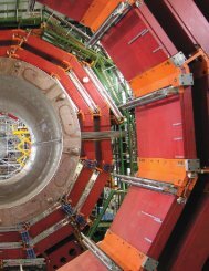
Media channels lit up February 17th with a stunning image (fig. 1) and story about a<br />
three year project by Rice <strong>University</strong> scientist Jane Tao and collaborators, who mapped<br />
out the coat of the PsV-F virus, one of very few viruses containing double-stranded<br />
RNA to be studied at the atomic level. Many diffraction images were needed to create<br />
this detailed picture, which appeared online Feb. 25 in the journal Proceedings of the<br />
National Academy of Sciences 3 . The packing of molecules in the PsV-F coat proved to<br />
be surprisingly different from that in related viruses, a finding that will ultimately help<br />
researchers to understand the structure and function of viruses and uncover ways<br />
to fight viral infections 4-6 . Rice <strong>University</strong> press said: “If a picture is worth a thousand<br />
words, then Rice <strong>University</strong>’s precise new image of a virus’ protective coat is seriously<br />
undervalued. More than three years in the making, the image... could help scientists<br />
find better ways to both fight viral infections and design new gene therapies. The<br />
stunning image…was painstakingly created from hundreds of high-energy X-ray<br />
diffraction images and paints the clearest picture yet of the viruses’ genome-encasing<br />
shell called a ‘capsid’.”<br />
Changing channels to metallurgy and mechanical engineering, Matt Miller (<strong>Cornell</strong>)<br />
has been selected to receive the ASM Henry Marion Howe Medal for 2009 for<br />
his publication 7 , “Measuring Stress Distributions in Ti-6 Al-4V Using<br />
<strong>Synchrotron</strong> X-ray Diffraction.” This award honors the author<br />
whose paper has been selected as the best of those<br />
published in the journal Metallurgical and Materials<br />
Transactions for the prior year. Miller, who reports on<br />
his group’s many efforts in the cover article of this<br />
newsmagazine, points out that the paper cited for<br />
the award covers some of the first titanium data<br />
taken at CHESS and was the basis of the third<br />
chapter of graduate student Joel Bernier’s Ph.D.<br />
thesis. Now that work is responsible for him<br />
having to rent a tuxedo!<br />
Fig. 1: <strong>High</strong>-energy x-ray diffraction was<br />
used to reveal the structure of the protective<br />
protein coat of PsV-F.<br />
Credit: J. Pan & Y.J. Tao/Rice <strong>University</strong> 1<br />
Page 8 CHESS News Magazine 2009
The end of August saw news channels<br />
saturated with stories about a discovery<br />
of a “hidden treasure” in the art world.<br />
Jennifer Mass, chemist and senior scientist<br />
at Delaware’s Winterthur Museum and<br />
Country Estate, gave a keynote presentation<br />
on x-ray fluorescence to study buried<br />
painting layers at the August 19th, 2009<br />
American Chemical Society (ACS) meeting<br />
symposium, “Practical Applications of<br />
Surface Chemistry: Art and Sensing<br />
Applications.” Her presentation recounted<br />
work enabled by a collaboration with CHESS<br />
scientists Arthur Woll, Don Bilderback and<br />
Sol Gruner to develop a confocal x-ray<br />
fluorescence (CXRF) microscope to examine<br />
the chemistry – and ultimately see the<br />
color palette – of layers of paint buried<br />
beneath a later portrait. X-radiography<br />
of an N. C. Wyeth family portrait (c.<br />
1922-1924) revealed the presence of a<br />
second painting buried underneath the<br />
surface. CXRF was able to identify the<br />
chemistry of the buried paint layers and,<br />
ultimately, help Mass reconstruct the color<br />
palette. Mass added: “to date, there have<br />
been no published studies on N.C. Wyeth’s<br />
painting materials and methods, and so this<br />
research will not only elucidate a buried<br />
painting but also contribute to the extant<br />
N.C. Wyeth art historical scholarship and<br />
attribution decisions. The <strong>Cornell</strong> <strong>University</strong><br />
synchrotron source is currently the only<br />
facility for the joint confocal XRFand XRF<br />
intensity mapping of buried paintings.” This<br />
story received streaming video coverage of<br />
the ACS press meeting and was the topic<br />
of the NPR Science Friday radio interview<br />
as well as print coverage by the <strong>Cornell</strong><br />
Chronicle, CHESS and lightsources.org 8-12 .<br />
This summer saw a particularly large (and<br />
welcomed!) group of undergraduate<br />
student research interns at Wilson<br />
Laboratory. CHESS and MacCHESS hosted 7<br />
students in research projects, who filled out<br />
an unusually large summer community of 41<br />
undergraduates including 11 participating<br />
in the CLASSE Research Experiences for<br />
Undergraduates (REU) program, 18 students<br />
in a CMS program in high-energy physics<br />
and 6 students providing technical support<br />
and upgrades for the CESR-TA program.<br />
One REU student, Elizabeth Brost, worked<br />
with scientists Peter Revesz and Don Hartill<br />
on “Vibration Studies at CHESS.” Liza, a<br />
Physics major at Grinnell College, configured<br />
a test station using a seismic accelerometer<br />
with fast-fourier-transform analysis to<br />
characterize mechanical vibrations and<br />
component stability at a number of critical locations – e.g. x-ray optics and<br />
beam position monitors - around the lab. Peter Melich and Adam Putzer<br />
formed a “dynamic duo” working with Arthur Woll to upgrade the confocal x-ray<br />
fluorescence scanning stage to perform “topographic” measurements. Peter and<br />
Adam, both <strong>Cornell</strong> juniors majoring in Applied and Engineering Physics, wrote<br />
Labview programs and machined and configured translation stages, encoders,<br />
and automated dial indicators to create topographic-like scans of 3-dimensional<br />
objects, similar to skimming across a surface as an atomic-force microscope does.<br />
Their hope is to dramatically speed up x-ray fluorescence scans of surfaces by<br />
following the interfacial surface directly, rather than having to scan an entire 3D<br />
volume (fig. 2).<br />
Fig. 2: Rapid, “topographic-like” x-ray fluorescence imaging involves following the<br />
surface (below) instead of having to scan the full 3D volume of the specimen (top).<br />
Michael Lyons, a <strong>Cornell</strong> junior majoring in Electrical and Computer Engineering,<br />
worked with Phil Sorensen, Bob Seeley and Ernie Fontes to help design and<br />
build a computer-automated apparatus that will be used to carefully control<br />
the heating and cooling process of vacuum equipment. The so-called “bakeout”<br />
process is used to heat vacuum equipment to high temperatures to accelerate<br />
the removal of adsorbed or trapped water from vacuum vessels and parts. Mike<br />
made progress using the EPICS control system to automate heating and reading<br />
temperatures and pressures. Paul Grigas, a junior studying Operations Research<br />
at <strong>Cornell</strong>, worked with Laura Houghton, Kathy Dedrick, Phil Sorensen and Ernie<br />
Fontes to examine ways to improve web-enabled databases to track the user<br />
community at CHESS. CHESS uses databases to keep track of the hundreds<br />
of student and scientist visitors each year who share dozens of scientific<br />
instruments. Paul explored modern software options and identified three<br />
candidate packages that are being considered for a next generation system.<br />
Gavrielle Untracht, a <strong>Cornell</strong> junior majoring in Applied and Engineering<br />
Physics, worked with Tom Szebenyi and Don Bilderback to improve the<br />
fabrication of tapered-glass capillary x-ray optics. She learned how to run the<br />
computerized glass puller that makes x-ray optics for CHESS use (the optics<br />
make micron diameter x-ray beams for our staff and our users). She has also<br />
spent a considerable amount of time writing Labview code to analyze the farfield<br />
x-ray intensity patterns formed by imperfect glass capillaries, hoping that<br />
CHESS News Magazine 2009 Page 9
those patterns can be used to pinpoint the sources of error in the figure and surface perfection of the glass. Rachel Pauplis, a<br />
<strong>Cornell</strong> junior in Physics and Asian studies, worked with Irina Kriksunov, Chae Un Kim and Marian Szebenyi to study the process of<br />
pressure freezing protein crystals using a new apparatus being commissioned for MacCHESS users. Pressure freezing crystals is a<br />
fairly new technique that often results in better protein crystallography data by avoiding the need to use cryoprotectant additives,<br />
among other benefits. Rachel, a neophyte at the start, helped pinpoint necessary improvements to the apparatus and procedures<br />
which should, ultimately, make it easier to apply pressure cooling to users’ crystals on a routine basis.<br />
As you can see, this year we had a sizable group of productive<br />
<strong>Cornell</strong> students working on research projects. For the coming<br />
years, CHESS has requested support for programs that would allow<br />
us to continue to recruit <strong>Cornell</strong> students as well as those from<br />
wider regional and national pools. We look forward to continuing<br />
our summer tradition of working with enthusiastic young<br />
scientists in training.<br />
References:<br />
1. Debashis Ghosh, Jennifer Griswold, Mary Erman, and Walter<br />
Pangborn; “Structural Basis for Androgen Specificity and<br />
Oestrogen Synthesis in Human Aromatase”, Nature 457 (7226),<br />
219-223 (2009)<br />
2. The original news release can be found at: http://www.hwi.<br />
buffalo.edu/newsroom/Press_Release_09/January/1_8_09.pdf<br />
3. Published online before print February 25, 2009, doi: 10.1073/<br />
Rachel Pauplis<br />
pnas.0812071106; PNAS 106 no. 11, 4225-4230 March 17, 2009<br />
4. Read the original Rice Report here: http://www.media.rice.edu/media/NewsBot.aspMODE=VIEW&ID=12128<br />
5. Visit the Tao research group for more information: http://www.bioc.rice.edu/~ytao/index.html<br />
6. See an interesting video explanation of virus structure and function<br />
that includes quotes from eminent CHESS user Michael Rossmann: http://www.livescience.com/health/090217-virus-coat.<br />
html<br />
7. J.V. Bernier, J.-S. Park, A.L. Pilchak, M.G. Glavicic, and M.P. Miller; “Measuring Stress Distributions in Ti-6Al-4V Using <strong>Synchrotron</strong><br />
X-Ray Diffraction”, Metallurgical And Materials Transactions A 39a, 3120 (2008)<br />
8. The ACS meeting archived video news conference is here: http://www.ustream.tv/recorded/2009896<br />
9. NPR Science Friday radio interview with Jennifer Mass: http://www.npr.org/templates/story/story.phpstoryId=112105590<br />
10. Coverage of the development of the technique is here: http://news.chess.cornell.edu/articles/2007/WollWyeth.html<br />
11. Science writer Anne Ju of the <strong>Cornell</strong> Chronicle wrote the following summary (PDF): http://www.news.cornell.edu/stories/<br />
Aug09/WyethColor.html<br />
12. Lightsources.org coverage (PDF): http://www.lightsources.org/cms/pid=1003645<br />
Page 10 CHESS News Magazine 2009
Staff in Focus - John Kopsa<br />
In March of 1988 John Kopsa, CHESS<br />
Machinist, began working at the <strong>Cornell</strong><br />
Plantations mowing the grass and<br />
planting trees. A year later, a call was<br />
placed to John, asking him if he would<br />
come and hang some lead/steel panels<br />
for x-ray shielding of the experimental<br />
hutches over at Wilson Lab, to help<br />
build a new “East” research area for the<br />
<strong>Cornell</strong> <strong>High</strong> <strong>Energy</strong> <strong>Synchrotron</strong> <strong>Source</strong><br />
(CHESS). He agreed.<br />
After the panels were done, Boris<br />
Batterman (Director Emeritus), offered<br />
John a permanent position at CHESS.<br />
By the time the East area was completed<br />
it was time to rebuild the West section;<br />
that was in 1993. John was involved<br />
with the plumbing and vacuum work.<br />
John Kopsa working in the CHESS Machine Shop.<br />
Laura Houghton<br />
When the construction was finally<br />
done, John moved into the machine<br />
shop with Basil Blank and Walt Protas<br />
(Equipment Machinist). It was there that<br />
he began to do machine work. On April<br />
20th, 2000 he became a Journeyman<br />
Toolmaker. Through a correspondence<br />
course and hands on training, John<br />
completed the New York State<br />
Department of Labor requirements for a<br />
Tool and Die Maker.<br />
Except for a period of time spent<br />
assisting with the build of G-line, the<br />
machine shop is where John can still be<br />
found. His time in the machine shop<br />
has been spent building the equipment<br />
to fill the East, West, and G-line stations.<br />
He has touched almost every aspect<br />
of the experimental equipment<br />
throughout the lab.<br />
According to John, “The best part of the<br />
job has been keeping the Staff Scientists<br />
humble, especially Ken Finkelstein”.<br />
He told me that he is also looking<br />
forward to seeing what the ERL (<strong>Energy</strong><br />
Recovery Linac) will bring and how the<br />
lab will change.<br />
“I met my wife at Wilson lab. We got<br />
married in 2000 and have a fantastic<br />
young daughter on the high honor roll<br />
who loves Math & Science”, John states<br />
proudly. “We live in a big farmhouse<br />
spending a lot of time taking care of the<br />
yard and over two acres of flower gardens.<br />
Shell, my wife, and I are looking forward<br />
to riding our bikes this summer”.<br />
John enjoys many different genres<br />
of music which can almost always be<br />
heard when entering the machine shop.<br />
He is a diehard fan of the Grateful Dead<br />
as well as Johnny Cash. How’s that for a<br />
combination<br />
He takes great pride in his work, is<br />
dedicated, and is a well respected<br />
member of the CHESS team.<br />
1999<br />
2007<br />
... a few words from John’s supervisor, Dana Richter ...<br />
John has been involved in most of the<br />
large projects in the lab over the past 20<br />
years. He started out putting together our<br />
experimental hutches when he first came<br />
here in 1989. The work involved putting<br />
up large shielding panels and forming<br />
and placing concrete shielding blocks.<br />
He has also installed cooling and exhaust<br />
systems. John is our expert at fabricating and<br />
assembling optical tables and translation stages.<br />
Many people do not realize that John and<br />
the hutch assembly crew often would put<br />
little notes inside the hutch walls as they<br />
put them up and we have found some of<br />
them as we have upgraded beam lines.<br />
He now spends most of his time in the<br />
machine shop where he has become<br />
proficient with the numerically controlled<br />
milling machine. John makes many of<br />
the parts used throughout Wilson Lab.<br />
CHESS News Magazine 2009 Page 11
Facility Upgrades, Networking and Computing<br />
Chris Conolly<br />
C-line Upgrades and New Capabilities<br />
Ernie Fontes and Ken Finkelstein<br />
D-line Upgrades and New Science Capabilities<br />
Ernie Fontes and Detlef Smilgies<br />
Education & Outreach<br />
Lora Hine<br />
MacCHESS Advances: Microcrystallography & More<br />
Station F3<br />
Marian Szebenyi<br />
Ulrich Englich<br />
XPaXS: Improved Data Acquisition & Real-Time Analysis at CHESS<br />
Darren Dale<br />
CHESS <strong>High</strong>-pressure B1/B2 Update<br />
Zhongwu Wang<br />
The <strong>Cornell</strong> <strong>Energy</strong> Recover Linac:<br />
update on a future source of coherent hard x-rays<br />
Don Bilderback, Bruce Dunham, Georg Hoffstaetter, Alexander Temnykh, and Sol Gruner<br />
Facility <strong>High</strong>lights<br />
Page 12 CHESS News Magazine 2009
Facility Upgrades, Networking and Computing<br />
Chris Conolly<br />
<strong>Cornell</strong> <strong>High</strong> <strong>Energy</strong> <strong>Synchrotron</strong> <strong>Source</strong>, <strong>Cornell</strong> <strong>University</strong><br />
Transparent upgrades<br />
“We have done so much with so little for so long<br />
we can do anything with nothing”<br />
-- author unknown<br />
While not completely true, here at CHESS,<br />
sometimes it feels that way. I like to think we<br />
could do almost anything with what we have, and<br />
sometimes we do. As I have looked over the list<br />
of projects over the past few years, a surprising<br />
number of upgrades have taken place, improving<br />
the capabilities of almost every experimental<br />
station. Some are quite obvious to the casual<br />
user of the lab, but many are not and deserve<br />
to be mentioned. Driven to innovate, the CHESS<br />
Operations staff, through a collaborative effort,<br />
make ideas into a reality. In the following article,<br />
I will describe some of the upgrades that you may<br />
or may not have heard about and who made them<br />
into a reality.<br />
Video, driving motors, racks that roll, and<br />
(hopefully) no more floods<br />
Upgrades can take on many forms and affect<br />
users in many different ways. One that improves<br />
the quality of x-rays directly is the installation of<br />
additional video beam position monitors (VBPMs)<br />
at F1 and C1 stations, which were designed and<br />
installed by operator and designer Tom Krawczyk.<br />
Viewing the F-line wiggler beam directly after it is<br />
reflected off the collimating mirror, the F1 VBPM<br />
speeds tuning by eliminating the laborious process<br />
of taking burns, which process involves opening<br />
the helium chamber, overriding the equipment<br />
protection system, and running back and forth<br />
from the cave to the control area numerous times.<br />
Diamonds have become our best friends at<br />
CHESS lately. The move towards more UHV<br />
monochromators has created a need for VBPM’s<br />
that do not rely on visible light fluorescence of<br />
helium. To the rescue are movable, thin diamond<br />
foils that can be moved into the beam as needed.<br />
They use the same video cameras and processing<br />
software, and they have proven very useful for<br />
beam alignment and even position monitoring, if<br />
the experiment can tolerate a slight loss of flux.<br />
Current systems have been installed on the D- and<br />
G-beam lines.<br />
Former CHESS Operator and current electronics<br />
designer, Eric Edwards,<br />
has made a revolutionary<br />
upgrade to how we move<br />
motors throughout the<br />
lab. In designing what he<br />
terms the MDCP -- which<br />
stands for motor drive,<br />
control, and power -- Eric has<br />
simultaneously reduced the<br />
size and cost to drive a motor<br />
while increasing the reliability<br />
and usability of the system.<br />
Now, many sets of long cables<br />
and separate components<br />
have been reduced to a<br />
single chassis, a set of motor<br />
cables, Ethernet, and power.<br />
Eric packaged a Galil motor<br />
controller and eight Gecko<br />
brand motor drives coupled<br />
to an in-house designed<br />
circuit board, all sandwiched<br />
into a 2U electronics chassis.<br />
Installations on optical tables<br />
and diffractometers have significantly<br />
decreased the time required to move<br />
experiments around the laboratory<br />
floor and get them running again.<br />
Through the efforts of Ernie Fontes,<br />
Ellen Kathan, Phil Sorenson and<br />
many others the beam line front<br />
end electronics have been slowly<br />
evolving over the past few years.<br />
Gone are the days of electronics<br />
scattered into any space<br />
available under the beam lines.<br />
Lead-shielded rolling electronics<br />
racks have been installed in the<br />
CESR tunnel near each front end.<br />
Each rack is the nerve center for its<br />
beam line -- containing ion pump<br />
controls, thermocouple monitors,<br />
motor drives, position monitor<br />
supplies, and computer networking.<br />
Tethered to the front end by a thick<br />
bundle of cables and wires, the<br />
wheels allow the rack to swing out<br />
of the way of activities and repairs<br />
taking place on CESR. Although staff<br />
must still crawl around under the<br />
The F3 XRF optical table setup can roll into<br />
place in minutes and be fully operational<br />
a short time later with its own on-board<br />
MDCP motor drives.<br />
A typical rolling rack which serves<br />
as the nerve center for each front<br />
end. This particular rack belongs<br />
to A-line and houses PE monitor<br />
electronics, ion pump controllers, a<br />
thermocouple local monitor, patch<br />
panels, a networking switch, a<br />
multiport serial to Ethernet adapter<br />
and power conditioning.<br />
CHESS News Magazine 2009 Page 13
eam lines we no longer have to troubleshoot electronics<br />
while we are there.<br />
A detector system recently installed by Ted Luddy, one<br />
of our long-time CHESS Operators, is one which users<br />
will, hopefully, never get to experience -- the flood<br />
detection system. In the past, whenever there was<br />
a breach in any of the five different water systems<br />
around the lab, the first indication of a problem<br />
was an alarm from a water sensor in the CLEO pit, the<br />
lowest point in the lab. As one can imagine, the probability<br />
that equipment damage would occur was high, leading<br />
to machine down time and experiments being delayed.<br />
The CHESS<br />
Flood Alarm.<br />
Green lights indicate<br />
that all CHESS areas are dry.<br />
Now a series of sensors have been installed in critical areas -- such as beam line front ends, optics caves, and station roofs<br />
-- to give advanced warning. The system pages the CHESS Operator directly and also sounds an alarm in the CESR control<br />
room whenever the slightest drip is detected. The system uses an off-the-shelf continuity sensor coupled with a relay box<br />
designed and built by Ted in our own electronics shop. We all sleep a little better knowing that thousands of gallons of<br />
water from one of our many water systems has less of a chance of flooding our experimental floor. Thank you for that, Ted.<br />
Another behind the scenes upgrade is a gas flow monitoring system installed by Operator Dave Jones. You may have<br />
wondered how a CHESS Operator knew you had set the gas flow to your flight tube or ion chamber a bit too high. Simply<br />
put, units have been installed for CHESS East, West, and G-line to log the pressure and flow of the helium and argon<br />
distributed gases. For example, a quick glance at the signal-monitoring web page tells the Operator whether the lab’s<br />
helium usage is normal or excessive, and then he or she can easily and efficiently make the proper adjustment. The system<br />
helps us to see trends develop and allows us to reduce usage, when necessary, saving thousands of dollars a year in costs.<br />
The compact F3 white beam mirror. Notice the<br />
external bender mechanism at the top indicating<br />
the mirror has a bounce down configuration.<br />
It’s all done with mirrors<br />
Operators Tom Krawczyk and Aaron Lyndaker traveled to the APS to use the<br />
long-trace profilometer to characterize three newly-fabricated glidcop white<br />
beam mirrors. C1 and F3 each now have an 800mm-long mirror installed in<br />
their front ends. Compact new benders for them have been designed, which<br />
locate the motor driven actuator on the exterior of the UHV mirror chamber<br />
to facilitate ease of installation and repair, if ever needed. The UHV chambers<br />
have been designed to<br />
take up the minimum<br />
of volume to be able<br />
to fit into the tight<br />
space available on the<br />
respective front ends. A<br />
spare for the aging A1<br />
collimating mirror has<br />
also been fabricated and<br />
is standing by.<br />
The F3 monochromator<br />
second optics cart as<br />
model and in reality.<br />
CHESS Engineer Alan Pauling has redesigned the F3 monochromator<br />
for better stability and increased capabilities to accept beam from<br />
the new F3 white beam mirror. The re-fit includes a new set of white<br />
beam slits located in their own upstream chamber and a longer second<br />
crystal travel stage. Ever creative, Alan used an existing port on the<br />
monochromator chamber to support the first crystal stages to allow<br />
overlap with the second crystal stage for low energy experiments. The<br />
new monochromator can use silicon or multilayer optics over an energy<br />
range of 1keV to 135keV and bandwidths up to 0.6%.<br />
Sharing space with the F3 monochromator in the large helium<br />
coffin, the F1 monochromator required some re-design to avoid an<br />
interference with the first crystal mount of the F3 monochromator. Alan<br />
designed a new compact cooled crystal bender which incorporates a<br />
more reliable bending mechanism coupled to a new copper block with<br />
Page 14 CHESS News Magazine 2009
e-routed cooling lines. During the project, the helium<br />
chamber and all its internal components were cleaned to<br />
near UHV standards and all radiation-damaged stepper<br />
motor wiring was replaced. The complete motor drive<br />
system for the 56 motors located in the F-cave was replaced<br />
with MDCPs and re-located from the cave roof to a leadshielded<br />
rack inside the F-cave. Overall, the re-fit has<br />
proven to be reliable and the additional capabilities have<br />
been put to good use.<br />
Alan Pauling and Aaron Lyndaker put the finishing<br />
touches on the C-line front end before the CESR<br />
dipole magnet is slid back into place.<br />
A phased reconstruction of C-line began during the 2009<br />
winter down period. Replacement of a section of CESR<br />
beam pipe required the removal of the CESR dipole magnet<br />
next to C-line and afforded CHESS the luxury of space for<br />
one short week to complete the installation of a new front<br />
end. A new copper-flared chamber and CESR X-ray Beam<br />
Size Monitor optics chamber were installed along with the<br />
previously mentioned white beam mirror. The C1 mono<br />
box was raised up a few inches to be able to accept the<br />
mirror reflected beam. This required the monochromator<br />
offset to change, which led to a complete overhaul of the<br />
existing monochromator, followed by motor rewiring and<br />
plumbing. Additional pink and white beam safety bricks<br />
were also installed in the coffin. Completion of phase one<br />
of this project reduces the number of beryllium windows in<br />
the beam line down to one, which will be removed in phase<br />
2 to allow the x-ray beam-size monitor (xBSM) project to<br />
gather data at low energy. The final phase will be new UHV<br />
optics, which will allow C1 to utilize low energy x-rays and<br />
continued xBSM data collection.<br />
Vacuum goes for a walk<br />
The CHESS Vacuum group, under the direction of group<br />
leader Bob Seeley, has endured many changes of venue<br />
over the past few years. Bumped from their long-time home<br />
just off the CHESS control area by the ERL project, the group<br />
has become mobile. A small fraction of the CESR vacuum<br />
lab has been turned over to CHESS for general vacuum<br />
processing needs, but larger fabrication projects have had<br />
to take place elsewhere. An additional space has been<br />
carved out of Room 128 -- a clean room built specifically for<br />
ERL development -- for clean UHV assembly work. Many of<br />
the stockpile of flanges, controls, and spare parts are now<br />
shared with the CESR group. CHESS specific components<br />
and tools now share space with the CHESS Glass Puller in<br />
RM 180. Although nomadic, productivity has increased<br />
significantly for this group with many difficult installations<br />
under their belt. The group should be commended for<br />
being flexible enough to work in this unusual situation.<br />
Multiple networks and processors<br />
On the computing front, a new private control network<br />
has been installed that is isolated from the general CHESS<br />
laboratory network. A need developed for a secure network<br />
for devices controlled over Ethernet. The implementation of<br />
Parker Compumotor motor drives and later the new MDCP<br />
drives forced the computer group to look seriously at a<br />
separate secure network. Each station has been connected<br />
to the private network to accommodate motor drive<br />
upgrades, present and future. MacCHESS has also joined<br />
the trend, installing its own local networks at A1, F1, F2 and<br />
F3. Keeping the flow of data local to each station will also<br />
have the benefit of keeping network issues localized and<br />
speeding data transfers.<br />
Out in the CESR tunnel, each beam line front end has<br />
been configured utilizing the private network to allow<br />
remote management of motor drives, ion pump controls,<br />
and, potentially, thermocouple and position monitors. By<br />
using multiport serial to Ethernet converters, devices can<br />
communicate bi-directionally with an EPICS display located<br />
at the CHESS<br />
control area, which<br />
allows operations<br />
staff to view status,<br />
trends, and even<br />
control the devices.<br />
One advantage of<br />
this system is to<br />
allow access to the<br />
hardware located<br />
in the CESR tunnel,<br />
without calling<br />
for a machine<br />
access; this reduces<br />
downtime for user<br />
experiments.<br />
Operator Ellen Kathan<br />
completed wiring one<br />
of the rolling racks in<br />
the CESR tunnel. This<br />
rack contains all of the<br />
pump controllers for<br />
the F hard bend and<br />
wiggler front ends.<br />
Consolidation of the computers that process the VBPM<br />
signal to a central location has been led by Operator Lee<br />
Shelp. Using USB converters to bring the many video signals<br />
back to the CHESS control area eliminates the need for<br />
individual computers taking up space throughout the lab,<br />
and also minimizes the potential for failure from multiple<br />
computer systems running multiple programs.<br />
CHESS News Magazine 2009 Page 15
The design group has seen many upgrades to the popular AutoCAD Inventor CAD suite over the past few years. CAD<br />
workstations have all been upgraded to dual-processor machines running 64-bit Windows to utilize all of the functionality<br />
of the program. This upgrade also benefits ANSYS users, who are now able to churn out simulations at an ever-increasing<br />
rate.<br />
Smaller is always better in the CHESS world. This is certainly the case when it comes to diagnosing and testing motor<br />
problems quickly. Operations staff now have a few netbooks available to allow one person to single-handedly move<br />
motors locally rather than requiring a second person to run them remotely. Using an ssh session over the wireless<br />
network, operators can quickly locate and repair motor problems in the caves and CESR tunnel. These basic machines are<br />
inexpensive, lightweight, and run a variety of operating systems. They have also found a use running RGAs and viewing<br />
signals using a specially developed fast-monitoring windows program.<br />
New Blood<br />
The changes around the lab aren’t simply with systems upgrades and<br />
modifications. We have added some new faces to our staff as well.<br />
Within the past year, we have hired two new CHESS Operators. Rich Jayne<br />
jumped right in with both feet to design, fabricate, and install a MAR345<br />
detector cradle in the B2 station. The overhead rail system gives ample<br />
clearance for experiments, while allowing effortless motion in the x, y,<br />
Operator Rich Jayne inspects<br />
the MAR 345 detector in the<br />
B2 station.<br />
and z directions as well as in rotation.<br />
Solenoid actuated brakes lock the<br />
detector firmly in place. A less involved<br />
mount for our other MAR345 detector<br />
was requested for the A2 station on short<br />
notice and Rich delivered -- cobbling<br />
together a motorized table from spare<br />
parts found around the lab. Alignment time of the detector for the Miller<br />
group has decreased by an order of magnitude and allowed the group to<br />
collect data sooner in their allotted beam time. A positive outcome for all.<br />
Our other new Operator, Aaron Lyndaker, has brought excellent design skills<br />
to the group. Beam line front-end design at CHESS requires that we be able<br />
to think and work in very tight spaces. In most cases, removing components<br />
from a beam line makes this easier, but when removing beryllium windows this<br />
isn’t the case. Once the beryllium windows are removed, a differential-pumping<br />
section must be installed to protect CESR from the higher pressure at the experiment.<br />
Differential pumping requires additional valves, pumps, and apertures to work. Aaron was able to incorporate all of these<br />
into a clean design for D-line. So far, our first foray into windowless beam lines has been a success, allowing the CESR xBSM<br />
experiment to happen in a very short time frame. As part of this project, the old D-line monochromator was scrapped<br />
and a new UHV set of optics, designed by Tom Krawczyk, was installed. The detector used by the xBSM experiment is not<br />
UHV compatible, so a single, very thin 5 micron diamond window was purchased to separate the detector chamber from<br />
accelerator vacuum. Using a complex pressure-balancing system, designed by Engineer Jim Savino, the pump-down and<br />
venting of the xBSM detector chamber has been automated using a PLC. A single button press allows the user to access<br />
the detector at any time while protecting the UHV vacuum system connected directly to the accelerator vacuum.<br />
There is also a new face in the computer group, Shijie Yang, who will help with hardware and software maintenance and<br />
system administration. He will also help train and supervise staff, students, and visitors in the many software packages<br />
used around the lab.<br />
These are but a few of the upgrades CHESS has seen over the past few years. Many thanks for the countless hours spent by<br />
the tireless CHESS staff that has resulted in less downtime and increased capabilities. Who knows what future upgrades are<br />
in store for CHESS but one thing is certain, the CHESS staff will be there with creativity and a drive to make them a reality.<br />
Page 16 CHESS News Magazine 2009
C-line Upgrades and New Capabilities<br />
Ernie Fontes and Ken Finkelstein<br />
<strong>Cornell</strong> <strong>High</strong> <strong>Energy</strong> <strong>Synchrotron</strong> <strong>Source</strong>, <strong>Cornell</strong> <strong>University</strong><br />
This article will highlight developments at C-line, including recent upgrades, new science capabilities and long-term plans.<br />
Recall that C-line is a bend-magnet-source beamline that features very flexible x-ray optics and has one of the smallest x-ray<br />
beam source sizes of any CHESS beamlines. Primary use of the beamline has been for energy dependent resonant (anomalous)<br />
scattering including 4-circle diffraction, anomalous SAXS, EXAFS and XANES. In addition the station is used for x-ray topographic<br />
studies, multiple beam diffraction, high pressure x-ray spectroscopy, and specialized x-ray optics development. See article on<br />
page 58 by Richard Jones – Topography of Diamonds at CHESS helps Nuclear Physics Program at JLAB.<br />
Several years ago, while writing a proposal for CHESS<br />
funding starting in 2008, the scientific staff identified<br />
research capabilities that were missing from CHESS and<br />
new scientific communities they would benefit. At the top<br />
of the list was the need to extend the x-ray beam energy<br />
range down to 2 keV to accommodate low energy x-ray<br />
applications. This will open new opportunities in biology,<br />
condensed matter and environmental sciences and give<br />
the CHESS staff invaluable experience in a new spectral<br />
region. A unifying theme of the new scientific capabilities<br />
was the need to perform resonant elastic x-ray scattering,<br />
anomalous SAXS, crystallographic phasing, solution x-ray<br />
absorption (XANES), and to study quantum correlations by<br />
gaining access to low-energy absorption edges. If C-line<br />
could reach down to 2 keV, figure 1 shows the elemental K,<br />
L, and M edges which would then become accessible.<br />
In the past, CHESS has not supported x-ray applications<br />
below 6 keV because our beamline designs traditionally<br />
Fig. 1: Periodic table showing low-energy absorption edges that will become<br />
newly accessible at the C1 station after technical upgrades. Blue, red, and green<br />
indicate K,L,M edges, respectively.<br />
included two beryllium vacuum windows, typically 0.01<br />
inch ultrapure foils. The engineering purpose of these windows was to separate the downstream x-ray optics box atmosphere,<br />
typically helium, from the sensitive upstream ultra-high-vacuum environment needed for the particle accelerator. While<br />
providing vacuum protection, these windows also dramatically attenuate photons with energies below 6 keV, making it<br />
impractical to collect data at light element absorption edges, for example. To overcome this limitation and improve the<br />
capabilities of C line, the engineering staff outlined a plan summarized in figure 2. It involves upgrading the beamline front-end,<br />
beam transport, x-ray optics, and experimental hutch components to be compatible with (clean) vacuum equipment and to<br />
include differential pumping segments, and fast-acting sensors and valves to protect against component failures. With upgraded<br />
pumping and protective valves in place, we can remove all windows during normal x-ray operations.<br />
Fig. 2: Schematic plan view of the major<br />
upgrades proposed for the C-line beamline<br />
and C1 station. At left, a new white beam<br />
vertical-focusing 800 millimeter glidcop mirror<br />
was installed and used. Placeholders for a<br />
low-energy mirror and new high-vacuum x-ray<br />
optics box are show. Long term we hope to<br />
extend the length of the hutch: shielding wall<br />
positions indicate “old” (dashed) and “new”<br />
positions. The new positions would extend the<br />
hutch approximately two meters so that the<br />
diffractometer could be located at a 1:1 focusing<br />
arrangement. Not shown off the left side is a<br />
small vacuum box to hold the CESR-TA pinhole<br />
camera optics.<br />
CHESS News Magazine 2009 Page 17
In addition to new capabilities for low-energy x-ray<br />
experimentation, removing windows from the beamline also<br />
makes it possible for a group of accelerator physicists to study<br />
the operation of the storage ring at lower beam energy, e.g.<br />
2.0 GeV. The CESR-TA group, as they are called, is using CESR<br />
as a test accelerator and model of the positron damping ring<br />
proposed for the International Linear Collider project 1 . In their<br />
studies, the C beamline and station will be used to create a pinhole<br />
camera to view the electron bunches stored in CESR. The<br />
pin-hole camera is formed by putting a small slit or pin-hole in<br />
the tunnel, upstream of the C-line shielding wall, and placing a<br />
diode array detector in the downstream-most station position.<br />
Since the work is done with a low-energy particle beam (2<br />
GeV) the windowless arrangement of the beamline is needed<br />
to maximize the photon flux for their measurements. These<br />
measurements will be done outside the x-ray run schedule, and<br />
so will not affect x-ray users at C1. A similar beam-size monitor<br />
was commissioned last year on D-line to study positron beams;<br />
see the discussion of the D-line upgrades in a separate article.<br />
The C-line upgrades included an extensive rearrangement and<br />
replacement of upstream vacuum components over the course<br />
of two CESR down periods. In the upstream-most position,<br />
a new copper-flared chamber was installed to contain and<br />
aperture the x-ray beam when it first exits the storage ring.<br />
Just downstream, a new small vacuum chamber was added to<br />
allow the CESR-TA group to install apertures and pinholes for<br />
source imaging experiments. During x-ray running periods,<br />
this pinhole optics is completely withdrawn and does not<br />
interfere with the x-ray user beam. Downstream of the main<br />
line beamstops, pieces were installed to accommodate a new<br />
white beam vertical focusing mirror. Fabricated by CHESS<br />
with help from LBNL, this new 800 millimeter-long glidcop<br />
mirror is internally-cooled and located for 1-to-1 focusing of<br />
the CESR source at the center of the C1 diffractometer in the<br />
experimental hutch. This mirror will improve C line in four<br />
ways: 1) focusing will increase flux density (photons/second/<br />
area) at the sample by about 3 times, without increasing<br />
angular divergence or reducing energy resolution. 2) The mirror<br />
can be used for (vertical) angle collimation to produce a more<br />
parallel x-ray beam. This reduces vertical beam size at the<br />
sample and increases spectral flux density (photons/second/<br />
unit bandwidth). 3) The mirror also reduces total power on the<br />
monochromotor first crystal, typically by a factor of 2. 4) It can<br />
be adjusted to remove high energy harmonics of the primary<br />
beam.<br />
To satisfy all the goals of the project we need to completely<br />
replace the x-ray optics box, but for the running periods in 2009<br />
we only had time to modify existing parts to accommodate<br />
variable height of mirror reflected beam. These modifications<br />
included redesigning the monochromator to permit height<br />
adjustment of the first crystal, and installation of a novel beam<br />
viewer system downstream of the crystals. The viewer uses<br />
a 40 micron thick, 100 mm diameter silicon wafer to convert<br />
x-rays to visible light. Light from the crystal is reflected by a<br />
mirror to a video camera. The thin crystal will be a very useful<br />
diagnostic and alignment tool because it can intercept filtered<br />
white beam, mirror reflected “pink beam” and/or image Laue<br />
diffraction from the first crystal. These capabilities allow us<br />
to use the x-ray beam for precise positioning of the mirror<br />
and mono first crystal. We have also added “phi-adjustment”<br />
(rotation about the surface normal) to the first crystal. Phiadjustment<br />
is critical when using asymmetrically cut crystals<br />
(diffraction planes NOT parallel to the surface), for example<br />
to expand the beam for topography studies (as was needed<br />
during the topography work by Richard Jones). The support<br />
structure for the second mono crystal has also been rebuilt for<br />
greater stability and for operation at fixed height above the<br />
white beam. To accommodate these improvements we have<br />
also rebuilt the white beam slit system for the wider range of<br />
vertical beam position, raised up the optics box to match the<br />
new range of beam positions, built new apertures to ensure<br />
safe handling of white and pink beams, and added a capability<br />
for white beam use in C-hutch by the accelerator physics group.<br />
Work is also ongoing to design new instruments for the<br />
experimental hutch to meet goals to expand science<br />
capabilities at C line. One project involves design of an x-ray<br />
emission spectrometer for collecting x-ray fluorescence<br />
with high energy resolution over a large solid angle 2 . This<br />
capability is being built in collaboration with Serena DeBeer<br />
George 3 , a new <strong>Cornell</strong> chemistry professor who is interested<br />
in development and application of x-ray based spectroscopies<br />
to probe electronic structure in biological and chemical<br />
catalysis. In particular, she studies transition metal active<br />
sites that are often centers of catalytic activity. Active sites<br />
provide inspiration for biomimetic model chemistry and for<br />
understanding homogeneous catalysis. Once the emission<br />
spectrometer is perfected it will become available to all CHESS<br />
users. The present design will collect about 10 times more solid<br />
angle than is possible with our large aperture single element<br />
solid state detectors (e.g Vortex), and it will provide energy<br />
resolution matched to the width of emission<br />
lines (see figure 3). This will allow collection of:<br />
weak emission, closely spaced lines, and lines<br />
that are very close in energy to the incident<br />
beam. We plan to couple this spectrometer<br />
to a fast readout, low noise position sensitive<br />
detector to permit simultaneous data collection,<br />
over a range of energy sufficient for line shape<br />
analysis.<br />
Continued on pg. 21<br />
Page 18 CHESS News Magazine 2009<br />
Fig. 3: Schematic design for the high-efficiency triple-crystal x-ray fluorescence<br />
detector. The incident x-ray beam (from left) excites fluorescence in the specimen, and<br />
that light is collected by three spherically-bent silicon crystals and focused to a highcount-rate<br />
photon counting detector. Shielding and helium flight paths are not shown.
D-line Upgrade and New Science Capabilities<br />
Ernie Fontes and Detlef Smilgies<br />
<strong>Cornell</strong> <strong>High</strong> <strong>Energy</strong> <strong>Synchrotron</strong> <strong>Source</strong>, <strong>Cornell</strong> <strong>University</strong><br />
CHESS’s popular D1 station, utilizing synchrotron radiation<br />
from a hard-bend dipole magnet and a multilayer<br />
monochromator, has both a versatile optical system and a<br />
5-meter long hutch (Figure 1). Sharing the smallest x-ray<br />
source size at CHESS with C-line, D1 has been extensively<br />
used for small and wide angle scattering as well as<br />
microbeam experiments with glass capillaries to create x-ray<br />
beams on the scale of 50 nanometers to 50 microns. Recent<br />
applications include grazing-incidence small- and wideangle<br />
x-ray scattering on thin films of soft materials such<br />
as block copolymers 1 , conjugated polymers 2 , nanocrystal<br />
assemblies 3 and nanoporous films 4 as well as high-energy<br />
small-angle scattering in conjunction with diamond anvil<br />
cells 5 , and microbeam SAXS and WAXS studies 6 . D1 has also<br />
supported a development program for new experimental<br />
techniques such as an evaluation of the potential of<br />
Laue diffraction for structure determination of protein<br />
microcrystals 7 or fluorescence imaging of large-scale<br />
paintings 8 and Roman tombstones 9 .<br />
At about the same time the accelerator physics<br />
group was proposing to use the CESR storage ring<br />
as a “test accelerator” (TA) for part of the R&D aimed<br />
at the international linear collider (ILC). Using the<br />
flexible lattice of CESR the TA group wanted to<br />
create a prototype ultralow emittance positron<br />
Fig. 1: Conceptual plan to improve the D1 experimental program by lengthening<br />
the user space by 2 meters (old wall position shown). The new high-vacuum x-ray<br />
optics box is already installed and commissioned, and D1 has delivered a total of<br />
12 weeks of user operation within the old experimental hutch (dashed).<br />
A few years ago, during an exercise to identify strategic<br />
long-term plans to improve CHESS stations and beamlines,<br />
it became clear that the size and scope of the soft-matter<br />
science program being supported at D1 was “bursting at<br />
the seams.” For example, new demand has been growing<br />
steadily to study thin-films either in static specimens or<br />
in-situ during solvent vapor conditioning. Technically,<br />
the beamline front-end and optics had not been<br />
upgraded in almost two decades. In particular, the helium<br />
monochromator box that housed the synthetic multilayer<br />
mirrors was in poor shape and the unclean environment<br />
led to carbon-like deposits on the multilayer surfaces that<br />
needed to be cleaned off periodically.<br />
This exercise resulted in replacing the old helium optics<br />
box with a high-vacuum enclosure and a conceptual design<br />
to lengthen the experimental hutch (see figure 1). The<br />
extra space became available with the demise of the high-<br />
energy physics program at the decommissioned<br />
CLEO detector. The longer hutch would allow<br />
access to SAXS studies with higher resolution<br />
and/or at higher beam energies. A new optics<br />
box was designed to provide rapid changeover<br />
between multiple multilayer optics with different<br />
wavelength ranges, thus cutting down on set-up<br />
and realignment time.<br />
and electron damping ring of the sort that might become part of<br />
the injector system for the ILC. In this study they needed to setup<br />
a pinhole camera to image the electron and positron bunches,<br />
using the CHESS x-ray beamlines C1 and D1 close to the former<br />
interaction region. Using a fast detector, the group hoped to<br />
be able to measure the size and shape of individual bunches of<br />
charged particles, with photons emanating from a single pass<br />
of the bunches through the bend magnet source. Because this<br />
work would be done with a machine energy of 2.0 GeV, where the<br />
x-ray flux is peaked at 1 keV, the accelerator physicists requested<br />
that the targeted beamlines have all beryllium vacuum windows<br />
removed, in order to avoid absorption of low-energy x-rays<br />
coming down the line.<br />
Marrying the needs for better x-ray science capabilities with the<br />
accelerator group requests, the CHESS design, technical and<br />
vacuum groups designed an upgrade plan to accomplish these<br />
goals. Pictured in figure 2, the upstream D beamline was almost<br />
completely replaced with ultra-high-vacuum compatible flight<br />
tubes, apertures, a differential pumping stage to separate storage<br />
CESR hard bend dipole magnet<br />
quadrupole<br />
CESR-TA<br />
optics box<br />
D1 optics box<br />
Fig. 2: The new windowless D1 front-end. The x-ray beam enters from the right, traveling<br />
downstream to the left through a series of beamstops, a beam viewer, and differential<br />
pumping chambers. The D1 optics box is described in more detail in the text and in Figure 3.<br />
CHESS News Magazine 2009 Page 19
ing ultra-high vacuum from the high vacuum typically achieved<br />
in optics boxes, as well as removable thin diamond foil x-ray<br />
beam viewers to assist line-up.<br />
For the CESR-TA project a small vacuum optics box as close to<br />
the storage ring as possible was added. This small box is used<br />
by the accelerator group to hold a small pinhole, Fresnel zone<br />
plate, or coded aperture that will create an image of the positron<br />
source. During these special “TA” runs, all D1 hutch equipment<br />
(two full CHESS optical tables) is removed and the CESR-TA<br />
group rolls into the x-ray station a large vacuum detector box<br />
that has an ultra-thin diamond window with a pressure balance<br />
system designed by CHESS. This box houses a high-speed pindiode<br />
linear array detector that measures the projected size of<br />
the x-ray source.<br />
The old D1 x-ray optics box was replaced by a high-vacuum<br />
chamber with all vacuum-compatible motors, a large<br />
turbomolecular pump, gate valves before and after the optics<br />
for isolation of vacuum cells, a set of adjustable white beam<br />
slits, and a second downstream thin diamond foil x-ray beam<br />
viewer (figures 2 and 3). When the x-ray beam passes through<br />
the diamond foil beam viewer it creates a visible light image that<br />
is recorded by a video camera. Coupled with custom software<br />
designed by CHESS scientist Peter Revesz, the in-situ video<br />
images of the x-ray beam are extremely helpful for diagnostics<br />
on beam shape, position, and stability.<br />
The new D1 multicrystal monochromator contains three pairs<br />
of multilayers of varying properties. The first set is the tried and<br />
true 30Å Mo:B 4<br />
C multilayer made by the APS optics group that<br />
has been D1’s workhorse monochromator over the past four<br />
years 10 . Although somewhat damaged by prolonged operation<br />
in the old helium box, there are still good parts left. In the last<br />
running period of Spring 2009, the x-ray beam remained at a<br />
beam<br />
limiting<br />
slit set<br />
optional<br />
mirror<br />
long translation<br />
x table<br />
multi<br />
layer 2<br />
multi<br />
layer 1<br />
single spot, and it showed no signs of degradation over an<br />
initial four week user-mode operations period. Typically this<br />
multilayer covers the 8 keV to 15 keV energy range, but can<br />
get as low as 6 keV at increased offset. The second multilayer<br />
set is again a matched set, 21Å W:B 4<br />
C by Osmic. This<br />
multilayer was chosen to cover the hard x-ray range from 15<br />
keV to 30 keV. Originally conceived for fluorescence imaging,<br />
it is now also being tested for high-pressure SAXS and GIWAXS<br />
for an extended scattering range.<br />
The third multilayer set is an experimental one for exploring<br />
new optics configurations. The d-spacings of the Mo:B 4<br />
C<br />
multilayers were purposely mismatched with 21 Å for the<br />
upstream multilayer and 25 Å for the downstream multilayer,<br />
resulting in a beam that is somewhat bent down from the<br />
horizontal. A third optical element, a rhodium-coated mirror,<br />
is used to bend the beam back up to the horizontal plane,<br />
working close to the Rh critical angle. Since multilayer<br />
scattering angles and the critical angle of the mirror both<br />
scale inversely proportional with energy, this configuration<br />
can be maintained throughout the energy range of 10-20 keV.<br />
The Pd mirror generates an appropriate energy cut-off for<br />
higher harmonics, so that the third and higher orders cannot<br />
pass. This will result in a D1 beam with much less higherenergy<br />
contamination.<br />
As an additional option, the mirror can be slightly detuned<br />
towards lower incident angles, resulting in a slightly bent<br />
down beam that could enable grazing incidence experiments<br />
from liquid surfaces. Again, as multilayer Bragg angles and<br />
relevant critical angles have the same energy dependence,<br />
this mode can be maintained throughout the energy range. A<br />
future upgrade could add a bender to this mirror to increase<br />
flux on the samples at the cost of a small extra angular<br />
divergence, while maintaining a well-defined incident angle<br />
on samples. The advanced mirror options still remain to be<br />
commissioned at the time of writing.<br />
The multilayer set-up rests on a solid internal x-translation<br />
table so that different multilayers can be brought into the<br />
beam via remote computer control. This avoids the problem<br />
of having to re-align the optical tables in the hutch after<br />
changing multilayers. All monochromator motions use<br />
vacuum-compatible motors and bearings. Vacuum of better<br />
than 10 nanoTorr was maintained under beam and motor<br />
moving after careful conditioning. The whole monochromator<br />
assembly can be leveled by an external 3-point actuator set.<br />
Additional optical elements are a set of white beam slits<br />
limiting the incident beam to the beam that is needed.<br />
These internally water-cooled slits are controlled by external<br />
actuators via bellows, and maintain a clean vacuum even<br />
under heat load. Finally, a set of fixed slits behind the<br />
multilayer optics will be used to clean up the beam exiting<br />
the monochromator; in particular, to remove small amounts<br />
of diffuse scattering from the multilayers. This slit set, to be<br />
installed before the upcoming run, is also controlled through<br />
an external actuator via bellows.<br />
3-point mount for leveling<br />
Page 20 CHESS News Magazine 2009<br />
Fig. 3: Inside detail of the new D1 vacuum multicrystal<br />
monochromator. Details given in text.
One aspect of the upgrade that has not yet been tackled is to lengthen the experimental hutch. This will require a significant<br />
restructuring of the thick and heavy shielding walls, as well as moving some quantity of wiring. Short of moving those walls,<br />
though, the downstream-most wall of the hutch had a 12-inch hole bored through it. This was done as an optional, alternate<br />
means to locate the “TA” beam size detector as far as possible from the storage ring source. This option has not yet been exploited.<br />
Another option under discussion is adding a full second D-line hutch at the far end of the CLEO enclosure, that would serve for<br />
USAXS, microbeam scattering, or coherent scattering applications as well as for CESR-TA at higher resolution.<br />
We thank the members of the CHESS Mechanical Design Group headed by Jim Savino, the Operations Group headed by Chris<br />
Conolly, and the Vacuum Group headed by Bob Seeley for all their great work. Particular thanks to Aaron Lyndaker who designed<br />
the bulk of the vacuum system including the new monochromator box, and Tom Krawczyk who designed, assembled, and<br />
commissioned the complex insides of the multi-crystal monochromator.<br />
References:<br />
1. Christine M. Papadakis, Zhenyu Di, Dorthe Posselt, and Detlef-M. Smilgies; “Structural Instabilities in Lamellar Diblock Copolymer<br />
Thin Films During Solvent Vapor Uptake”, Langmuir 24, 13815-13818 (2008)<br />
2. Mingqian He, Jianfeng Li, Michael L. Sorensen, Feixia Zhang, Robert R. Hancock, Hon Hang Fong, Vladimir A. Pozdin,<br />
Detlef-M. Smilgies, and George G. Malliaras; “Alkylsubstituted Thienothiophene Semiconducting Materials: Structure – Property<br />
Relationships”, J.Am. Chem. Soc. online (2009)<br />
3. Danielle K. Smith, Brian Goodfellow, Detlef M. Smilgies, and Brian A. Korgel; “Self-Assembled Simple Hexagonal AB2 Binary<br />
Nanocrystal Superlattices: SEM, GISAXS and Substitutional Defects”, J. Am. Chem. Soc. 131, 3281–3290 (2009)<br />
4. Sivakumar Nagarajan, Mingqi Li, Rajaram A. Pai, Joan K. Bosworth, Peter Busch, Detlef-M. Smilgies, Christopher K. Ober,<br />
Thomas P. Russell, and James J. Watkins; “An Efficient Route to Mesoporous Silica Films with Perpendicular Nanochannels”, Adv.<br />
Mater. 20, 246–251 (2008)<br />
5. Zhongwu Wang, Ken Finkelstein, and Detlef Smilgies; “Exploring New Physics of Nanoparticle Supercrystals by <strong>High</strong> Pressure<br />
Small Angle X-ray Diffraction”, CHESS News Magazine, pg 56 (2009)<br />
6. Jessica S. Lamb, Sterling Cornaby, Kurt Andresen, Lisa Kwok, Hye Yoon Park, Xiangyun Qiu, Detlef M. Smilges, Donald H.<br />
Bilderback, and Lois Pollack; “Focusing Capillary Optics for use in SAXS Solution Scattering”, J. Appl. Cryst. 40, 193–195 (2007)<br />
7. S. Cornaby, D.M.E. Szebenyi , D.-M. Smilgies , D.J. Schuller , R. Gillilan , Q. Hao, and D.H. Bilderback; “Feasibility of One-Shot-per-<br />
Crystal Structure Determination using Laue Diffraction”, (to be published)<br />
8. A.R. Woll, J. Mass, C. Bisulca, M. Cushman, C. Griggs, T. Wazny, and N. Ocon; “The Unique History of the Armorer`s Shop: an<br />
application of confocal x-ray fluorescence microscopy”, Studies in Conservation 53, 93-109 (2008)<br />
9. J. Powers, N. Dimitrova, R. Huang, D.-M. Smilgies, D.H. Bilderback, K. Clinton, and R.E. Thorne; “Recovering Ancient Inscriptions<br />
by X-ray Fluorescence Imaging”, Zeitschrift für Papyrologie und Epigraphik (Bonn, Germany) 152, 221-227 (2005)<br />
10. Alexander Kazimirov, Detlef-M. Smilgies, Qun Shen, Xianghui Xiao, Quan Hao, Ernest Fontes, Don H. Bilderback, Sol M. Gruner,<br />
(continued from pg 18)<br />
In conclusion, during this upcoming Fall 2009 x-ray running period the technical and scientific staff at CHESS will<br />
commission new beamline, optics and station equipment that promise to significantly update and enhance the scientific<br />
capabilities of the flexible C-line experimental station. Our ambitious plans to produce low-energy x-ray optics and expand<br />
the size of the experiment hutch are still being developed. Look for more innovations during the coming year and contact<br />
the station scientist, Ken Finkelstein, with any questions or suggestions.<br />
References:<br />
1. See for CESR-TA: http://www.news.cornell.edu/stories/Aug09/cesrTA.html<br />
2. U. Bergmann et.al., Chem.Phys.Lett. 302, 119 (1999)<br />
3. http://www.chem.cornell.edu/faculty/index.aspfac=70<br />
CHESS News Magazine 2009 Page 21
Education and Outreach<br />
Lora K. Hine<br />
<strong>Cornell</strong> Laboratory for Accelerator-based Sciences and Education,<br />
<strong>Cornell</strong> <strong>University</strong><br />
I have the best job in the entire laboratory. Hands down. I have never<br />
made that proclamation out loud or even dared to whisper it to anyone<br />
sitting next to me; I am afraid people will finally catch on and realize<br />
that the work I do is much more enjoyable than what they are doing.<br />
Here’s why: I do not have to follow any taxing laboratory protocol; my<br />
instrumentation does not require fine-tuning; my results seldom (okay,<br />
never) end up in any peer-reviewed publications. My office resembles a<br />
toy store, where visitors spend more time scanning the shelves crammed<br />
full of useful materials (i.e. equipment) than they do maintaining eyecontact.<br />
My trip record forms display regional travel destinations<br />
that end in the words “school district” versus distant, more expensive,<br />
locations ending with “national laboratory”. My calendar is peppered<br />
with a variety of exciting events; camps, tours, teacher workshops, lab<br />
activities/demonstrations, and even the much anticipated student field<br />
trips. My work day includes interactions with a range of people as young<br />
as third grade school children to as senior as emeritus faculty members.<br />
My job, directing outreach activities at CLASSE and helping fulfill the<br />
broader impact criterion established by the NSF, is a truly remarkable<br />
appointment.<br />
One of the most rewarding aspects of this position is the time I get to<br />
spend with young children. They are so anxious to learn something, just<br />
about anything, about science. Before reaching puberty, children are<br />
blessed with a sense of awe and wonder; their minds are wide open and<br />
waiting to be filled. To a ten year old, nothing is cooler than looking at<br />
clusters of dead skin cells underneath a microscope! Discovering that<br />
Middle school science teachers Mary Anne Ritinski (IS 234<br />
Brooklyn) and Crisan Berina (IS 126 Queens) work together<br />
during the Summer Institute to build their own light bulb to<br />
observe the effects of resistance in a wire.<br />
you can blow a bubble using a toilet-paper tube is<br />
sheer ecstasy. Donning safety goggles to witness<br />
the shattering of a flower after being submerged in<br />
liquid nitrogen is, to an elementary student, as good<br />
as life will ever get. After visiting with Wilson Lab as<br />
part of a class field trip, I have no doubt in my mind<br />
that these children run home and enthusiastically<br />
tell their family members about all of the fascinating<br />
science stuff they saw (and did!) that day. And, more<br />
importantly, they tell their parents and themselves<br />
that they want to learn more.<br />
During the last year, the laboratory has provided<br />
after-school enrichment programming for<br />
nearly 100 elementary school students. That’s<br />
a lot of kids receiving one-on-one, hands-on<br />
science programming outside of school hours!<br />
This programming is provided free of charge to<br />
any school within a sixty-mile radius of Ithaca.<br />
Many schools have children from disadvantaged<br />
backgrounds; their families live in remote, rural<br />
areas and they haven’t even heard of <strong>Cornell</strong><br />
<strong>University</strong>. Most programs run one hour a week<br />
after school for six weeks, which is just enough time<br />
for me to get to know the kids, figure out what they<br />
want to learn more about, and (hopefully!) inspire<br />
them to seek out science and be comfortable with<br />
it - not scared of it. The most popular program we<br />
deliver to schools on a regular basis is “Atoms for<br />
Kids!”, but “The Science of Bubbles” comes in a close<br />
second. During the Atoms program, students get<br />
to operate light microscopes, investigate crystal<br />
formation, study light spectra, and witness what<br />
happens to atoms inside of a bell jar. All of which is<br />
extremely cool stuff when you are a 3-5th grader….<br />
and still cool stuff when you are an adult.<br />
If only we could bottle the excitement of a fifth<br />
grade class and pass it along to class of high school<br />
students. By the time a typical high school physics<br />
class makes a trip to Wilson Lab, they are less<br />
enthralled by the wonders of science and are more<br />
concerned with grades, college, dating and a host<br />
of other distractions. This is not to say that these<br />
students are disinterested in science, but they are<br />
less enamored by its mysteries and more concerned<br />
with completing college applications! Some<br />
students have a genuine interest in conducting<br />
research, and it is the Lab’s good fortune to be able<br />
to provide some research experiences for high<br />
school students. During the past year, a number<br />
Page 22 CHESS News Magazine 2009
of high school students have worked alongside our laboratory’s<br />
scientists, involved in projects of value to their mentors. One<br />
CHESS researcher, Richard Gillilan, worked with Ithaca <strong>High</strong><br />
School student Sohyun (Sarah) Kim during the summer of 2007<br />
to help her write a Java program to analyze 100,000 digital<br />
images of crystal growth. This past summer, she gave a poster<br />
presentation on her work at the CHESS user meeting. Currently<br />
Sarah is volunteering in MacCHESS’s lab growing protein crystals<br />
for use in beam-line testing.<br />
In addition to structured internships, the laboratory hosts a large<br />
number of visiting high school students as part of class field trips<br />
to Wilson. Many science teachers, from as far away as Buffalo NY,<br />
visit the lab as part of their one (and usually only) field trip during<br />
the school year. On average, 250 high school students each year<br />
amble along the passageways of the laboratory, gawking at the<br />
massive collection of electronic gadgetry, dodging the occasional<br />
drip of tunnel-juice, and timidly asking questions about the<br />
scope of the research being done here. A tour of the facility just<br />
can’t but help some high school students feel a sense of awe<br />
and wonder about the opportunities that lie in store for them as<br />
budding young scientists.<br />
Having spent six years as a middle school science teacher, I have<br />
grown comfortable interacting with children at this age level<br />
and even more at ease with the teachers who choose to make a<br />
profession out of educating this age-group. Consequently, the<br />
bulk of the professional development opportunities available<br />
to teachers through the outreach program at the Laboratory<br />
are geared towards 6-8th grade science teachers. Contrary to<br />
popular belief, middle school students are wonderful to have in<br />
the science classroom. They are capable, curious and internally<br />
motivated to “do science”. They adore hands-on activities and<br />
investigations; they benefit tremendously from interactive<br />
experiences, and are not yet afraid to propose an explanation<br />
for observed phenomena. Much anecdotal evidence suggests<br />
that middle school is the time when students decide, somewhat<br />
subconsciously, that they enjoy or despise science. Knowing this,<br />
it is important that adults, especially teachers, fuel a student’s<br />
passion for science before they leave middle school. If not<br />
properly fueled, that passion may not ever be reignited.<br />
One can see how important it is that middle school science<br />
teachers have the capacity and training to confidently teach their<br />
students. The outreach program at Wilson lab has taken an active<br />
role in helping to provide science teachers with the professional<br />
Lincoln Street Elementary School<br />
(Waverly, NY)<br />
Students have a good time learning about<br />
surface tension and experimental<br />
design by blowing bubbles with various<br />
house-hold objects.<br />
African Road Elementary School<br />
(Vestal, NY)<br />
Students look through the spectroscopes they built<br />
to observe the different colors of light released by<br />
heated gas bulbs.<br />
development training they need by hosting the <strong>Cornell</strong> Physical Science Summer Institute for Middle School Science Teachers<br />
during the summer of 2008. The theme for the week-long institute was “Making Connections: What Science Research and Your<br />
Middle School Curriculum Have in Common”. The Institute was partially funded through grant money received from the New York<br />
State Education Department; the other funding came from money devoted to Outreach at CLASSE. The Institute, held at <strong>Cornell</strong><br />
for a week in July, provided eleven middle school science teachers from New York City with the opportunity to gain content<br />
knowledge aligned with NY State learning standards. It also provided teachers with the chance to interact with scientists who<br />
are conducting cutting-edge research and allowed participants to learn about state-of-the-art technology in the unique setting<br />
of a world-class research university. All participants earned one unit of graduate credit in Physics for the five days they spent on<br />
campus. A quote from one participant asked to reflect upon the week states; “My experience at the Physics Summer Institute was<br />
very exciting and informative. The hands-on explanations and the lectures from various experts in the field of physics can assist<br />
me in enhancing my knowledge in science as well as in delivering more research-based activities.”<br />
In addition to working with K-12 teachers and students, I am given the opportunity to interact with undergraduate students<br />
who spend time conducting research at our laboratory. These students, from diverse backgrounds and experience levels,<br />
are competent, motivated and frequently amaze me with their intellectual maturity. The science and engineering students<br />
participating in the Research Experience for Undergraduate (REU) program are selected from a large pool of applicants from<br />
CHESS News Magazine 2009 Page 23
throughout the country and come to Wilson Lab to work with faculty, research associates, and graduate students on a broad<br />
selection of research projects. These projects contain important elements of the overall research program at CLASSE; topics<br />
range from accelerator physics to microwave superconductivity to applications of synchrotron radiation in scientific research.<br />
During their final presentations delivered during the last week of the program, students showcase the complex research<br />
they have done and reveal the advanced level of thought and understanding required to work on projects alongside their<br />
<strong>Cornell</strong> mentors. Although these students work hard, they also play hard and take advantage of many social opportunities<br />
made available to them as part of the summer program. These college students live at the same dorm and hang out with REU<br />
students from other nationally sponsored programs at <strong>Cornell</strong>. REU’ers can be found playing soccer, bowling, dining, riding<br />
bikes, or sightseeing in downtown Ithaca with their colleagues throughout the summer months.<br />
During the summer of 2008, seven of the ten REU students worked for ten weeks on substantive ERL-related research projects,<br />
the efforts of which will be referenced and utilized by future staff and students. For instance, REU student Justin Hugon worked<br />
with research scientist Don Bilderback and technician Tom Szebenyi to reduce the vibration that occurs during current x-ray<br />
capillary optics fabrication. Improvements in capillary design will be necessary to take full advantage of the synchrotron<br />
radiation generated by the ERL. Upon completion of the program Justin, currently a physics major at Rhodes College, stated<br />
that his experience at CLASSE was beneficial and rewarding; it helped convince him to pursue a doctoral degree instead of a<br />
bachelors or masters degree. For many REU students, the time spent in the program and on campus has encouraged them to<br />
seriously consider applying for graduate school at <strong>Cornell</strong> <strong>University</strong>. Seven students from past REU programs at Wilson Lab<br />
have continued their graduate work at <strong>Cornell</strong> and have enrolled in PhD programs or have pursued STEM (Science, Technology,<br />
Engineering, and Mathematics) teaching careers.<br />
Having a particle accelerator facility in the neighborhood is not only a unique attribute of the Ithaca community (how many<br />
cities advertise tours of a particle accelerator in their Visitor’s Guide), but it also offers remarkable opportunities for people<br />
throughout central New York to learn more about physics and other fields of science. Through the outreach program at CLASSE<br />
and nearly a dozen other STEM Outreach programs on campus, <strong>Cornell</strong> provides informal science education opportunities<br />
through a number of different of venues. A glimpse into the outreach program at the lab reveals staff involved in the following<br />
events: hosting informative, hands-on activity booths at local and state-wide science fairs; funding and offering workshops<br />
for campus-wide events such as Expanding Your Horizons and Career Explorations; participating in regional events to<br />
promote science literacy such as NanoDay and CCC Math Day; providing professional development training to educators from<br />
underperforming schools in New York City through the Science Sampler Series and Science Leadership Academy; escorting<br />
groups of community members through the tunnel that houses one of the most powerful tools for studying the atomic world;<br />
and many other examples. Through these volunteer efforts, and through the hard work of the outreach staff at CLASSE,<br />
thousands of people throughout the state of New York have been exposed to the many wonders of science. And hopefully,<br />
these people and others will recognize the important role that science research plays in their own lives and the lives of their<br />
children’s children.<br />
So, if you happen to be walking by my office<br />
and quickly glance at the vast collection of<br />
materials stacked on the shelves, see me<br />
carting tubs full of science equipment to and<br />
from the parking lot, or you see me escorting<br />
a young group of visitors throughout the<br />
Lab, ask me what I am doing and how you<br />
can help. The secret is out: I have the best<br />
job in the entire lab. And I will be more than<br />
delighted to share it with you!<br />
At the New York State Fair, Lora Hine explains to a visitor how<br />
potatoes create an electrochemical reaction between two probes<br />
in a Two Potato Clock which powers the digital clock. Visitors are<br />
invited to test various fruits and vegetables for themselves.<br />
Page 24 CHESS News Magazine 2009
MacCHESS Advances:<br />
Microcrystallography and More<br />
Marian Szebenyi<br />
Macromolecular Diffraction Division of<br />
<strong>Cornell</strong> <strong>High</strong> <strong>Energy</strong> <strong>Synchrotron</strong> <strong>Source</strong>, <strong>Cornell</strong> <strong>University</strong><br />
Microcrystallography<br />
Crystals of proteins and other biological macromolecules<br />
never grow very big, due to the “soft” nature of the<br />
molecules and the weakness of the forces holding them<br />
together. At CHESS and other synchrotron sources, it is<br />
routine to deal with crystals that are ~100 μm across, but<br />
how often do we need to work with even smaller crystals<br />
Ithaca <strong>High</strong> School student Sarah Kim, under the direction<br />
of MacCHESS staffer Richard Gillilan, surveyed thousands of<br />
crystallization attempts (Fig. 1), and concluded that about<br />
50% of initial crystals were in the “micro” category,<br />
and that many larger crystals have “good”<br />
and “bad” regions and would benefit<br />
from use of a microbeam to isolate<br />
the better regions.<br />
• Mike Cook, Scott Smith, and Bill Miller have installed<br />
rear-mounted, piezo-based motors for crystal centering<br />
at F2. Using these, the runout error of spindle rotation<br />
can be reduced below 1 μm, as verified using a LabView<br />
program developed by <strong>Cornell</strong> student Ivan Temnykh<br />
(Fig. 3).<br />
Fig. 1: Sarah Kim and<br />
the crystal-scoring<br />
Java interface that<br />
she designed almost<br />
completely by herself,<br />
with some help from<br />
R. Gillilan.<br />
MacCHESS provides users with an x-ray beam as small<br />
as 5 μm, using a focusing capillary (see p. 63), excellent<br />
crystal-viewing optics to center a microcrystal in the beam,<br />
and a very precise rotation stage to keep it there. Users<br />
have determined important<br />
structures from “difficult”<br />
crystals using this equipment,<br />
e. g. the SAM riboswitch<br />
reported by Ailong Ke’s group 1<br />
(Fig. 2). Seeking to enhance the<br />
microcrystallography facility,<br />
• Don Bilderback’s group is<br />
working to reduce slope errors,<br />
and hence improve focusing, of<br />
X-ray capillaries.<br />
Fig. 2: The SAM riboswitch<br />
structure, rendered using Jmol 2 .<br />
Fig. 3: Piezomotor-equipped rotation stage<br />
installed in F2, Ivan Temnykh, plot of runout<br />
error using the modified stage.<br />
• Dave Schuller has upgraded the crystal-centering<br />
software to be more robust, and to include computer<br />
control of crystal illumination, as well as auto-centering<br />
using the XREC software 3 (Fig. 4).<br />
• Marian Szebenyi has added to the ADX data collection<br />
software an option for automated scanning of a crystal to<br />
identify the best-diffracting regions.<br />
A new experiment using an old technique<br />
With the very intense beam that would be produced by<br />
future sources such as an ERL, very tiny samples could<br />
produce diffraction patterns, but radiation damage would<br />
severely limit the amount of useful data that could be<br />
obtained from each sample. An experiment at D1, led by<br />
graduate student Sterling Cornaby, investigated the use of<br />
Laue diffraction to record a few images from each of several<br />
crystals mounted together (Fig. 5). With the Laue technique,<br />
many diffraction data are recorded simultaneously, with no<br />
need to rotate the sample; hence it is ideal for obtaining as<br />
much data as possible in a very short time. The experiment<br />
demonstrated the feasibility of collecting Laue data from<br />
a group of crystals and obtaining a structure from them<br />
CHESS News Magazine 2009 Page 25
Fig. 4: Java-based crystal-centering user interface, incorporating<br />
excellent video quality, automated centering, computer control<br />
of camera and light settings, easy recording of images of crystal,<br />
singly, as a rotation series or as a video stream.<br />
shown that modifications to the standard technique may<br />
be useful, and have also furthered understanding of what<br />
is going on inside cryocooled crystals. Matt Warkentin,<br />
from Rob Thorne’s lab, demonstrated that a faster cooling<br />
rate, obtained by blowing away the cold gas layer above<br />
the surface of liquid nitrogen before plunging a crystal<br />
into the liquid, is often advantageous 5 (Fig. 6). A pressure<br />
cryocooling technique developed primarily by Chae Un<br />
Kim (first a graduate student of Gruner’s, now a MacCHESS<br />
scientist) can also improve the quality of cryocooled<br />
crystals; see pages 43 and 71 for recent interesting<br />
results using pressure-cooling. Warkentin and Kim have<br />
also considered cooling crystals in capillaries, and have<br />
looked at the behavior of cryocooled crystals when the<br />
temperature is varied; this is an active area of research that<br />
will enhance our understanding of what is going on inside<br />
cold crystals, and may lead to better data from crystals<br />
which do not take kindly to routine cryopreservation.<br />
(see p. 63 for more details); further studies are planned to<br />
ascertain the limits of the technique.<br />
Detectors<br />
As in the past, MacCHESS has served as a test bed for<br />
new x-ray detectors. The first of the latest generation<br />
of CCD-based detectors from Area Detector Systems<br />
Corp. (ADSC), the Q-270, was installed at CHESS in 2006<br />
for testing; a few problems (mostly in software) were<br />
discovered and corrected, and the detector was made<br />
available to users later that year. Generally similar to the<br />
earlier Q-210 and Q-315, the new detector differs in having<br />
increased sensitivity, for accurate measurement of weak<br />
reflections. ADSC is also collaborating with the Gruner<br />
group in developing a tiled pixel array detector (PAD) for<br />
crystallographic use. A prototype PAD was tested at CHESS<br />
in 2007, with promising results 4 . Modifications to ADX<br />
allowed easy switching between CCD and PAD devices,<br />
as well as collection of a series of PAD images at different<br />
detector locations, which could subsequently be<br />
assembled into a large image. The sensitivity of<br />
the PAD proved to be similar to that of the Q-210<br />
CCD, but the dynamic range is much higher<br />
and the readout time much less. No geometric<br />
distortion corrections are necessary for the<br />
PAD, and background subtraction is easily done<br />
with existing software; yet to be developed are<br />
corrections for edge effects, and procedures to<br />
scale and combine multiple small PAD images<br />
into one in real time. See p. 54 for the latest on<br />
PAD’s.<br />
Temperature and pressure<br />
Typically, macromolecular crystals are<br />
cryocooled by plunging into a container of liquid<br />
nitrogen, and then maintained at about 100 K<br />
for data collection. Recent experiments have<br />
Page 26 CHESS News Magazine 2009<br />
Fig. 5: Collection of microcrystals on a MicroMesh mount, for<br />
use in Laue experiment at D1.<br />
SAXS and SAD<br />
Over the last few years there has been increasing interest<br />
by structural biologists in conducting small angle x-ray<br />
scattering (SAXS) studies, and CHESS now offers facilities<br />
for SAXS including a new temperature-controlled sample<br />
cell, helium-filled flight paths, and expert<br />
advice. See the article on p. 50 for a full<br />
report on bioSAXS. The SAD (singlewavelength<br />
anomalous diffraction)<br />
technique, using the signal from heavy<br />
atoms such as Se or Hg, is the most<br />
common way to phase structures when<br />
no appropriate model is available for<br />
molecular replacement. At CHESS, A1 is<br />
suitable for Se-SAD and F1 for Br-SAD,<br />
and F2 can be tuned to accommodate<br />
a number of elements with absorption<br />
edges between 7 and 14 keV. For<br />
elements with edges at lower energies,<br />
Fig. 6: Simple “hyperquenching” device for<br />
blowing away cold gas above the surface of<br />
a liquid nitrogen bath.
down to slightly below 6 keV, the F3<br />
station, with multilayer optics, presents<br />
another option; see sidebar.<br />
Station upgrades<br />
A number of changes have been made to<br />
improve users’ productivity and comfort:<br />
Station F3<br />
Ulrich Englich<br />
Macromolecular Diffraction Division of<br />
<strong>Cornell</strong> <strong>High</strong> <strong>Energy</strong> <strong>Synchrotron</strong> <strong>Source</strong>, <strong>Cornell</strong> <strong>University</strong><br />
• Robust safety shields which open and<br />
close automatically.<br />
• Motorized detectors which roll back<br />
automatically when a hutch is opened,<br />
and which can be moved using ADX.<br />
• Up-to-date computing hardware<br />
and software, including an extensive<br />
collection of standard crystallographic<br />
software.<br />
References:<br />
1. C. Lu, A.M. Smith, R.T. Fuchs, F.<br />
Ding, K. Rajashankar, T.M. Henkin,<br />
and A. Ke; “Crystal Structures of the<br />
SAM-III/S(MK) Riboswitch Reveal the<br />
SAM-dependent Translation Inhibition<br />
Mechanism”, Nat. Struct. Mol. Biol. 15,<br />
1076-1083 (2008)<br />
2. “Jmol: an open-source Java viewer<br />
for chemical structures in 3D”, http://<br />
www.jmol.org<br />
3. “Crystal Recognition” , http://www.<br />
embl-hamburg.de/XREC<br />
4. W. Vernon, M. Allin, R. Hamlin, T.<br />
Hontz, D. Nguyen, F. Augustine, S.M.<br />
Gruner, Ng.H. Xuong, D.R. Schuette,<br />
M.W. Tate, and L.J. Koerner; “First<br />
Results from the 128x128 Pixel Mixedmode<br />
Si X-ray Detector Chip”, SPIE<br />
Optics & Photonics Conference, San<br />
Diego, CA (August 26-30, 2007)<br />
5. M. Warkentin, V. Berejnov,<br />
N.S. Husseini, and R.E. Thorne;<br />
”Hyperquenching for Protein<br />
Crystallography”, J. Appl. Cryst. 39,<br />
805-811 (2006)<br />
The F3 station is shared between CHESS (e.g. x-ray topography studies,<br />
x-ray imaging, x-ray fluorescence) and MacCHESS (macromolecular<br />
crystallography). Darren Dale, the responsible scientist for CHESS,<br />
maintains all beamline components up to the hutch and is currently<br />
working on further enhancements. The station supports a variety of<br />
monochromators: Si or Ge crystals as well as multilayers of various<br />
bandwidths. For macromolecular experiments the new 0.22% multilayers<br />
are used. Recent improvements in the monochromator box now allow<br />
users to tune the energy between 5.9 and 15.4 keV (2.1Å – 0.81 Å). This<br />
range spans the K and L edges of most commonly used elements for<br />
anomalous dispersion experiments.<br />
In the hutch CHESS and MacCHESS have rolling setups on separate<br />
optical tables for quick and easy switch-over. A new 1.5m optical<br />
table has been designed for crystallographic purposes; it supports all<br />
experimental components on one platform. This greatly facilitates<br />
alignment procedures and overall stability. It also gave CHESS the<br />
opportunity to install a new “integrated motion controller and drivers<br />
unit” for the table motors, which is much more compact than the old<br />
controller. In addition, the 32 bit workstation for data collection and<br />
processing has been replaced with a modern 64 bit Linux based system<br />
similar to those at other MacCHESS beamlines.<br />
The station has been used mainly by MacCHESS personnel, the Crane<br />
group from <strong>Cornell</strong> and the Cingolani group from Upstate Medical<br />
<strong>University</strong>. Recent experiments at the station examined samples that<br />
contain anomalous scatterers, e. g. Xe, Fe and S. The results show that<br />
we can obtain an anomalous signal from an element as weak as sulfur,<br />
with data collected at 7.1 keV. Due to the increase in flux with the 0.22<br />
% multilayer monochromator, data collection times were significantly<br />
shorter (~ 5 times) compared to a data set taken from a similar sample at<br />
the F2 beamline. As an example of the quality of anomalous data from<br />
F3, the figure shows an anomalous difference Fourier map from horse<br />
hemoglobin, after refinement, contoured at 4 σ. The region depicted<br />
includes both heme groups and their protein surroundings. Large<br />
positive peaks (blue) appear at the positions of the iron atoms in the<br />
center of the hemes, and smaller peaks are visible for sulfurs, e. g. in the<br />
disulfide bond located slightly above and to the right of the left-hand Fe.<br />
CHESS News Magazine 2009 Page 27
XPaXS: Improved Data Acquisition<br />
and Real-Time Analysis at CHESS<br />
The Scanning X-ray Fluorescence Microscopy (SFXM) capability at CHESS draws users from diverse fields, including Environmental<br />
Science, Soil Science, Anthropology and Native American Studies, Dendrochronology and Classics. When I inherited responsibility<br />
for the F3 beamline, two of the elements essential for the success of this research program were already available: wide-bandpass<br />
multilayers to provide the intense monochromatic flux required for detection of elements in trace quantities; and singlebounce<br />
capillary x-ray optics capable of yielding microbeams at the sample position. In the past three years we have completely<br />
refurbished the F3 station and upgraded all of the sample manipulation hardware, which is now capable of scanning areas 30 cm<br />
wide by 30 cm tall and 5 cm deep, with step sizes below 1 micrometer if necessary.<br />
Scanning large areas with high resolution presents some new experimental challenges. To give a sense of scale, scanning an area 3<br />
mm by 3 mm with a 15 µm step size requires 40,000 independent measurements, and if integrated for 1 second per point the scan<br />
will take more than 11 hours to finish (development of new multi-element<br />
detectors will improve the throughput in the near future). We use the “spec”<br />
command-line program for data acquisition, which is familiar to seasoned<br />
synchrotron researchers but frustrating to many newcomers, see figure 1.<br />
When I first took over F3, we would use “spec” to start a scan, and then watch<br />
raw data scroll across the screen for 11 hours. The experience was similar to<br />
watching the screens of encrypted data in the movie “The Matrix”, where a<br />
willful suspension of disbelief is required to accept that the data are somehow<br />
meaningful.<br />
Many experiments required recording the full fluorescence spectrum at each<br />
point. The datasets were growing in size and becoming difficult to work with.<br />
Some peak-fitting routines were available to process the data after collection<br />
was complete, but on several occasions we discovered problems with a<br />
Fig. 1: Everybody’s first experience with the command line.<br />
dataset weeks after the experiment had ended. Clearly what we needed was<br />
an improved analysis capability, one that could fit fluorescence spectra with many overlapping peaks, determine the elemental<br />
concentrations from the peak areas, and update an element map in a graphical user interface in real time while the experiment<br />
is ongoing. We also wanted the ability to interact with the data in real time without disrupting the acquisition, for example by<br />
selecting a single pixel or region of interest in the image map and inspecting the raw fluorescence spectra and fit results or<br />
performing some kind of statistical analysis such as Principle Components Analysis or cluster analysis.<br />
In order to foster development of the multidisciplinary research program at F3, we have begun augmenting the flexible<br />
command-line interface with just such an intuitive graphical user interface for experimental controls and data processing (see<br />
figure 2). Working with <strong>Cornell</strong> undergraduate students, we have begun to develop XPaXS, an extensible set of packages for x-ray<br />
science. These packages are written in Python, which is an established, powerful cross-platform scripting language that allows<br />
scientists to focus more on science than<br />
the minutiae of computer programming.<br />
Python is emerging as the standard language<br />
for systems integration, in part due to its<br />
permissive open-source license (it can be<br />
used for both free and commercial projects),<br />
simple and elegant syntax and wide variety<br />
of scientific libraries, all of which enable<br />
rapid development of powerful, large and<br />
yet maintainable projects. Our software<br />
development work is done in cooperation<br />
with other successful free software projects.<br />
Page 28 CHESS News Magazine 2009<br />
Darren Dale<br />
<strong>Cornell</strong> <strong>High</strong> <strong>Energy</strong> <strong>Synchrotron</strong> <strong>Source</strong>, <strong>Cornell</strong> <strong>University</strong><br />
Fig. 2: Graphical user interface for HDF5 files<br />
and spec scan controls.
For example, SpecClient provides a<br />
python interface to the “spec” data<br />
acquisition program, and PyMca is<br />
used for advanced spectral fitting and<br />
composition analysis, both of which were<br />
developed at the European <strong>Synchrotron</strong><br />
Radiation Facility.<br />
The graphical user interface and<br />
improved data handling allow us to<br />
develop flexible and powerful tools for<br />
data inspection and analysis. Experiments<br />
that once provided only lines of text on<br />
the command line as feedback during the<br />
measurement now provide capabilities<br />
for real-time analysis and interactive<br />
inspection of data in a form that is most<br />
meaningful to the experimenter. The<br />
program is multithreaded, so it is possible<br />
to interact with the data even while both<br />
data acquisition and analysis are ongoing.<br />
It is possible to select a single point in<br />
a map, or drag out a region of interest,<br />
and inspect the fluorescence spectra to<br />
identify anomalies or bad data points, or<br />
to average over a heterogeneous sample<br />
in order to calibrate the measurement<br />
to a NIST standard. In the example<br />
illustrated in figure 3, all the spectra<br />
in a region of interest specified in the<br />
calcium mass fraction map are passed<br />
to PyMca for peak fitting<br />
and concentration<br />
determination, and<br />
the averaged results<br />
are compared with the<br />
accepted values.<br />
This acquisition and<br />
analysis package is<br />
developed with the hope<br />
that many will find it<br />
useful, and that many<br />
will contribute to — and<br />
take credit for — its<br />
development. Working<br />
with colleagues at the<br />
European <strong>Synchrotron</strong><br />
Radiation Facility, we have<br />
settled upon a simple<br />
common file format based<br />
upon the freely available<br />
HDF5 technology suite,<br />
which supports the<br />
compressed, binary<br />
HDF5 format developed<br />
specifically for scientific<br />
applications. HDF5 allows<br />
us to efficiently work<br />
with arbitrarily large and<br />
complicated datasets,<br />
loading only small subsets of the data<br />
into memory at any given time. We take<br />
advantage of computers with multiple<br />
processors and even computing clusters<br />
to process data in parallel, as quickly as<br />
possible. Many synchrotron techniques<br />
can be significantly enhanced by the<br />
ability to analyze and inspect relatively<br />
large datasets in various ways, both in<br />
real time during the acquisition and<br />
off-line after acquisition is complete.<br />
The software is designed to be easily<br />
extended and applied to other kinds of<br />
experiments and analyses, has already<br />
been used for analysis of EXAFS data,<br />
and is currently being extended to other<br />
kinds of experiments at CHESS as well.<br />
Users can revisit or reprocess their data<br />
after leaving the lab using the Python<br />
packages which are freely available on<br />
the internet. XPaXS and its dependencies<br />
are free, open-source projects that can be<br />
used on Linux, Windows and Macintosh<br />
OS-X. The source code is also available for<br />
download, so anyone can add whatever<br />
additional features they need, regardless<br />
of platform. Everyone is encouraged<br />
to contribute and take credit for their<br />
contributions.<br />
Documentation is a major focus of our<br />
project. A Users’ Guide is currently being<br />
developed, along with a Developers’<br />
Guide and Application Programming<br />
Interface reference to help those<br />
interested in adding new features.<br />
The documentation is created using<br />
modern documentation generation<br />
tools. The library documentation, online<br />
html and printable pdf documents<br />
are all generated from a common<br />
origin, so the entire documentation<br />
suite can easily be kept up to date.<br />
The documents are searchable, crossreferenced,<br />
and automatically indexed.<br />
The documentation in its current form<br />
is available at http://www.chess.cornell.<br />
edu/software/xpaxs.<br />
The documentation is a central and<br />
ongoing effort. The users guide for<br />
the SXFM program will be the primary<br />
focus in the near future, in order to<br />
provide users who wish to work more<br />
independently with the means of<br />
doing so. A comprehensive set of unit<br />
tests will be assembled to aid in future<br />
development and ensure trouble-free<br />
operation. We are developing several new<br />
features, such as a network-based video<br />
monitoring capability which is currently<br />
being developed to allow<br />
remote observation of the<br />
experiment and its progress.<br />
We are also planning to<br />
incorporate existing code<br />
with features similar to<br />
those available at the CXRO<br />
website for calculations<br />
of x-ray transmission,<br />
anomalous form factors,<br />
index of refraction, etc.<br />
The long range goal is to<br />
provide a framework such<br />
that additional packages<br />
can be added over time to<br />
provide all the components<br />
necessary for imaging,<br />
spectroscopy and scattering<br />
experiments, optics design<br />
and characterization,<br />
characterization of x-ray<br />
sources, and most likely<br />
other areas we have not yet<br />
considered.<br />
Fig. 3: (Top) Calcium mass fracton<br />
distribution in NIST citrus leaves<br />
standard reference. (Bottom) Spectrum<br />
averaged over a region of interest<br />
selected from the Calcium map and the<br />
fit produced by PyMca.<br />
CHESS News Magazine 2009 Page 29
CHESS <strong>High</strong>-pressure Stations (B1/B2) Update<br />
Zhongwu Wang<br />
<strong>Cornell</strong> <strong>High</strong> <strong>Energy</strong> <strong>Synchrotron</strong> <strong>Source</strong>, <strong>Cornell</strong> <strong>University</strong><br />
<strong>High</strong> pressure coupled with synchrotron x-ray diffraction is one powerful technique for discovering novel<br />
physics and chemistry with a wide spectrum of applications. CHESS has long been playing a significant role<br />
in the development of high pressure synchrotron facilities. To expand our research abilities, particularly in<br />
nanoscience and nanotechnology, we have made an effort to improve and update our high pressure facilities,<br />
to be capable of a series of new in-situ measurements of materials, including wide and small angle x-ray<br />
diffraction and Raman measurements at extreme conditions of pressure and temperature. Here, we highlight<br />
several modifications and developments at CHESS:<br />
1.<br />
2.<br />
3.<br />
4.<br />
Two beam lines for energy-dispersive and angle-dispersive x-ray diffraction are combined and<br />
merged into one versatile station. This modification not only keeps all experimental capabilities<br />
- energy-dispersive or angle-dispersive x-ray diffraction can be selected by repositioning two<br />
monochromator crystals - but also expands the hutch space, enabling introduction of a series of<br />
fixed and portable instruments for development of new techniques. The improved capabilities<br />
include a three-dimensional rotating stage for side x-ray diffraction, laser-excited Raman<br />
spectroscopy, a detector control system, a high temperature tuning system etc.<br />
Four-dimensional control for movement of the Mar345 detector is implemented. Slightly tilting and<br />
rotating the Mar345 detector enables an accurate calibration of the sample-to-detector distance<br />
and associated parameters. Most importantly, a new in-situ technique has been developed allowing<br />
measurement of both small and wide angle x-ray diffraction at various pressures and temperatures<br />
without multiple calibrations. Easy optimization of x-ray energy and sample-to-detector distance<br />
makes the two types of measurements possible during one single pressure run.<br />
Switching the x-ray source to white beam and using a large area image plate detector enable single<br />
crystal Laue diffraction under pressure.<br />
A series of side instruments become operational for users. These include two portable<br />
spectrometers for Raman, reflectivity and transmission spectra, mechanical and Electrical Discharge<br />
Machining (EDM) drillings, a high pressure gas loading system, optical microscopes, etc.<br />
Page 30 CHESS News Magazine 2009
The <strong>Cornell</strong> <strong>Energy</strong> Recovery Linac:<br />
update on a future source of coherent hard x-rays *<br />
Don Bilderback 1,2 , Bruce Dunham 3 , Georg Hoffstaetter 3 ,<br />
Alexander Temnykh 3 , and Sol Gruner 1,4<br />
1<br />
<strong>Cornell</strong> <strong>High</strong> <strong>Energy</strong> <strong>Synchrotron</strong> <strong>Source</strong>, <strong>Cornell</strong> <strong>University</strong><br />
2<br />
School of Applied Physics, <strong>Cornell</strong> <strong>University</strong><br />
3<br />
Laboratory of Elementary-Particle Physics, <strong>Cornell</strong> <strong>University</strong><br />
4<br />
Physics Department, <strong>Cornell</strong> <strong>University</strong><br />
*<br />
For the <strong>Cornell</strong> ERL Team, <strong>Cornell</strong> <strong>University</strong><br />
<strong>Synchrotron</strong> radiation research is still growing, with newer and more capable x-ray sources being constructed. Petra III<br />
in Hamburg, Germany and the NSLS II in Upton, NY are examples of storage rings under construction that are nearing<br />
the expected limits of storage ring performance. In contrast, linac-based sources such as energy recovery linacs (ERLs)<br />
and x-ray free electron lasers (XFELs) are still at an early stage of development, and have great potential for steady<br />
improvements in performance for many years to come.<br />
The ERL upgrade to the CESR ring described below<br />
promises to generate ultra-bright electron beams, and<br />
thus ultra-bright x-ray beams with dramatically smaller<br />
emittances and shorter pulse durations than those available<br />
from storage rings 1 . The high coherence and temporal<br />
properties of the ERL will have transformative, broad<br />
impact across the sciences and engineering by enabling<br />
numerous experiments that are now not feasible at even<br />
the most modern 3 rd generation storage ring sources;<br />
nor would many of these experiments be suitable for<br />
x-ray free electron lasers. Enabled science includes many<br />
types of imaging of materials and biological structures,<br />
macromolecular structure determination without<br />
crystals, effective nanoprobes for matter at higher static<br />
pressures than are presently feasible, and detailed studies<br />
of the structure of glasses, disordered materials, and<br />
polycrystalline materials. The ERL would be especially<br />
useful in cases where structure needs to be determined on<br />
objects for which structural details vary from one specimen<br />
to another, which is the case for most nanoparticles and<br />
biological cells and organelles. It would also allow the<br />
recording of extremely rapid events, so researchers<br />
can “visualize” rapid physical, catalytic and<br />
biological processes taking place on times scales<br />
down to 50 femtoseconds. Societal impacts<br />
will come in numerous areas such as life-saving<br />
medicines and drugs, new materials for better<br />
batteries, more efficient catalysts for fuel cells,<br />
better composite materials, smarter electronics, etc.<br />
The transverse emittance of the electron bunches<br />
used to generate x-rays determines the spectral<br />
brilliance and transverse coherence of the x-ray<br />
beams. Ideally, the emittance should be small<br />
enough to produce full transverse coherence of the<br />
x-rays, i.e., to produce a diffraction-limited x-ray<br />
beam. The underlying basis of an ERL is that, in<br />
principle, very low emittance electron beams can<br />
be generated from a laser-driven photocathode,<br />
and accelerated to high (GeV) energies without<br />
substantial emittance growth in linear accelerators.<br />
<strong>High</strong> brightness, highly coherent x-ray beams can then<br />
be generated from these electrons as they pass through<br />
undulators. Since the electron beam carries several<br />
hundred megawatts of beam power, this is feasible only<br />
if the electron beam energy is recovered after the x-rays<br />
are generated. Using a superconducting (SC) RF linac,<br />
essentially all the electron energy may be recovered by<br />
passing the beam through the linac a second time, 180 o<br />
out of phase with the accelerated beam, hence, the name<br />
<strong>Energy</strong> Recovery Linac. Although the basis of the ERL idea<br />
was suggested many years ago by Maury Tigner 2 , it only<br />
became practical for x-ray generation in the mid-1990’s,<br />
due to advances in superconducting linac technology and<br />
photoemission electron sources 3 .<br />
Phase 1a & 1b: Testing the first stages of the ERL accelerator<br />
The ERL group at CLASSE is in the midst of prototyping<br />
the technology that will be needed for a 5 GeV ERL facility.<br />
The most difficult and critical component in need of R&D<br />
is the injector; a full-scale prototype injector has now been<br />
assembled in the L0 area of Wilson Laboratory (Figure 1).<br />
The injector generates a beam of high average current, lowemittance<br />
electrons using a laser-driven photo-cathode and<br />
then accelerates them to relativistic energies up to 15 MeV.<br />
Fig. 1: Floor layout of the ERL test area in L0 of Wilson Laboratory, just south<br />
of CHESS East. From right to left: DC photocathode, superconducting linac,<br />
branch lines for diagnostics, and finally, a high power beam dump.<br />
CHESS News Magazine 2009 Page 31
A consequence of special relativity is that the mutual charge repulsion that tends to blow apart a bunch of electrons at low<br />
energy is counteracted at relativistic speeds. Thus, the difficult task of the injector is not only to generate a low emittance<br />
electron beam, but to preserve the emittance until relativistic energies are achieved. Figure 1 shows the layout of the test<br />
accelerator designed to generate ultra-low emittance bunches of electrons at a 1.3 GHz rate with up to 100 mA average<br />
current. This injector is now in the commissioning stage.<br />
The electrons are produced in a special cathode material using the photoelectric effect. A precisely shaped laser pulse is<br />
directed at the cathode, giving the electrons enough energy to escape. The ejected electrons are then accelerated across<br />
a small gap using a high voltage power supply. The cathode material is gallium arsenide (GaAs), which is commonly used<br />
for high speed electronics, in photomultiplier tubes, and in night vision goggles. To obtain efficient electron emission, the<br />
surface of the GaAs wafer must be as clean as possible and maintained at a vacuum level below 10 -11 torr. After cleaning,<br />
Fig. 2: Photocathode gun area. A vacuum of better than 10 -11 Torr<br />
has to be maintained around the photocathode to avoid ion back<br />
bombardment of the photocathode, which would spoil the lifetime of<br />
the photocathode by ruining the monolayer of Cs on the surface. A<br />
load-lock chamber facilitates quick change of the cathodes for testing<br />
and for renewing the Cs monolayer needed for the cathode to work well.<br />
Fig. 3: The superconducting (SC) linac consists of 5 SC cells<br />
in series. Each cell uses a waveguide to conduct 1.3 GHz<br />
microwave power from associated klystron transmitters on the<br />
mezzanine floor above. The cavities are cooled by liquid helium<br />
at 1.8 K from a closed-cycle refrigeration system. The linac is<br />
now functional.<br />
it is coated with very thin layers of cesium and fluorine, which act to reduce the work function, making it easier for the<br />
electrons to escape (Figure 2 shows the cathode preparation system). The properties of GaAs have been extensively<br />
measured 4,5 , demonstrating that it is currently the best cathode choice for obtaining low beam emittance and high average<br />
current.<br />
A very sophisticated laser system is required to produce bunches of electrons with the correct shape, power and time structure. It<br />
turns out that the shape of the outgoing electron pulse closely matches the shape of the incoming laser pulse, and the electron<br />
beam emittance can be reduced by choosing the correct shape. The spacing (frequency) of the pulses must also match the<br />
frequency of the RF accelerating cavities, which operate at 1.3 GHz. There are no commercial laser systems available to meet all of<br />
the needs for an ERL injector, thus we have built a custom laser using ytterbium (Yb) doped optical fibers.<br />
After the electron bunches are produced<br />
at the cathode and given an initial<br />
acceleration by the electron gun, they are<br />
boosted to high energy using a series of<br />
5 superconducting RF cavities (Figure 3).<br />
Each cavity can transfer up to 100 kW of<br />
microwave energy to the electron beam, for<br />
a total of 500 kW (1/2 of a million watts!).<br />
Superconducting cavities are used to<br />
overcome the heating problems that would<br />
occur with such large power. Figure 4<br />
shows the five high-power microwave tubes<br />
that provide the energy to the accelerating<br />
cavities.<br />
Fig. 4: Microwave generators<br />
produce the power needed to<br />
drive the superconducting linac.<br />
Page 32 CHESS News Magazine 2009
The final parts of the test set-up are diagnostic tools to measure the emittance of the electron bunches and its pulse duration<br />
before the beam is sent to a 0.5 MW beam dump.<br />
We are now starting the second phase of the ERL R&D program. The proposed research program addresses five critically important<br />
technology areas:<br />
1. Superconducting linac development. The ERL requires linacs capable of continuous duty (CW) operation at high current with<br />
short bunch lengths while preserving emittance and dealing effectively with higher order modes. A full linac cryomodule<br />
(somewhat similar to the injector linac, but with longer cavities and with much weaker power couplers because in the<br />
ERL it is the decelerated beam that fills the cavity with energy, not the power coupler) will be designed and fabricated at<br />
<strong>Cornell</strong>. Cryomodule component testing will be done collaboratively with several other institutions. The program includes<br />
development of requisite cavities, higher-order-mode absorbers, beam position monitors, in-vacuum cryomagnets, RF<br />
amplifiers and power couplers, and cool-down procedures.<br />
2. <strong>High</strong> brightness photoinjector development. Continued development will be performed on laser driven photoinjectors capable<br />
of delivering requisite current at high brightness and long photocathode lifetime. This includes R&D on new photocathodes,<br />
high voltage electron sources, drive lasers, and advanced beam simulation tools. Further R&D on the HV insulator is needed<br />
to reach the required 500 to 750 kV energy level from the electron gun.<br />
3. <strong>High</strong>-brightness electron beam physics and diagnostics. The program will address challenges of emittance preservation from<br />
the electron source, through the injector, merger, and transport loop sections via experiments and simulations on the <strong>Cornell</strong><br />
injector. Beam diagnostics to monitor bunch timing and position will be advanced, both for beam stability at the x-ray source<br />
points, and for simultaneously accelerating and decelerating bunches in the linacs.<br />
4. Beam dynamic effects will be investigated, such as ion trapping, short bunch behavior and other possible sources of instability.<br />
Beam loss mechanisms, impedance issues, failure modes and beam abort strategies will all be studied through overall system<br />
modeling. In each case, methods of mitigation and control will be studied.<br />
5. X-ray beamline components necessary to exploit ERL capabilities will be developed. These include novel undulators to exploit<br />
the identical horizontal and vertical emittances of an ERL, x-ray optics for high specific heat loads, coherence monitors, and<br />
detectors to effectively utilize the temporal possibilities of a coherent ERL source.<br />
Fig 5: Low-energy electrons are produced and accelerated to 5-10 MeV at the injector. They are raised to 2.5 GeV in the North Linac by traveling “on-crest”<br />
through the RF fields produced by the SRF cavities, turned around and raised to 5 GeV after passing through the South Linac. X-rays will be produced in<br />
undulators in the position of the blue arrows, mostly in a new building to be added to the east of Wilson laboratory. Electrons returning to the North Linac<br />
are shifted 180 degrees out of accelerating phase (by adjusting the path length) so that the electrons are now “off-crest” and their energy is recovered in<br />
both linacs before the spent electron beam is sent to the dump. There is room in the layout for a non-energy-recovered, fast-pulse beamline as shown by<br />
the red arrow.<br />
Phase II: the full-energy, 5 GeV machine<br />
The work of the Phase I development (described above) is designed to provide confidence and costing for a 5 GeV ERL that we<br />
would hope to build at Wilson Laboratory.<br />
The CESR tunnel and Wilson laboratory infrastructure will be reused for the ERL facility. Much of the ERL would consist of new<br />
construction to the East (above, in Figure 5) of the present CESR and Wilson Lab complex. A new partially-underground laboratory<br />
will be added to increase the number of x-ray beamlines and new tunnels will be bored to house the new linacs required. We<br />
already have a first round of plans and costing from ARUP, an internationally-based architectural and engineering company<br />
that has been contracted to develop plans for the civil engineering (buildings and tunnels) of the project. The present plans are<br />
CHESS News Magazine 2009 Page 33
for conceptual design purposes. We are presently optimizing the layout of tunnels, buildings and the machine to fit campus,<br />
performance, and cost constraints. For example, we are evaluating layouts with twin linacs in the same tunnel as well as versions<br />
in separate tunnels. When this work is completed, we plan to submit a conceptual design proposal to the NSF for a full-scale<br />
5 GeV ERL facility, including x-ray beamlines.<br />
The ERL design group is working on a<br />
Conceptual Design Report containing the<br />
following parameters table which shows<br />
various ERL operating modes. An ERL is<br />
more flexible than a storage ring, which<br />
opens new opportunities and a plethora<br />
of operating modes.<br />
There is a long list of items that are being<br />
worked on in parallel with work on the<br />
injector and the 5 GeV facility layout,<br />
including electron beam machine design,<br />
shielding wall design, collimators ahead<br />
of undulators, exit crotch design, etc.<br />
The x-ray group has begun planning for<br />
5 to 25 m long undulators and beamlines<br />
that extend outward to 70 m from the<br />
source. We have established preliminary<br />
working groups to conceive of beamlines<br />
in the following areas:<br />
1. Diffraction-limited x-ray scattering<br />
beamline suitable for soft-matter<br />
using SAXS, USAXS, WAXS and<br />
GISAXS techniques;<br />
2. Short-pulse repetitive pump-probe timing beamline for 100 femtosecond pulse work at a repetition rate of 100 kHz and a 2<br />
picosecond pulse length at a 1.3 GHz repetition rate. This will be useful for ultrafast time-resolved experiments;<br />
3. A beamline for coherent diffractive imaging and dynamic studies of bulk materials, interfaces and biological samples<br />
including techniques of intensity fluctuation spectroscopy, ptychography. Examples of application areas are dynamics of<br />
magnetic materials and the glass transition;<br />
4. Inelastic x-ray scattering (IXS) with meV resolution will be used to study the dynamical properties of materials at atomic to<br />
mesoscopic length scales. An ERL IXS facility has the potential to outperform all existing facilities, their proposed upgrades,<br />
and sources under construction by one order of magnitude more flux;<br />
rd<br />
5. A nanoprobe for making a 1 nm diameter x-ray beam at 10 keV with as much flux per square nm as most 3 generation light<br />
sources put into a square micron. This will make possible x-ray experiments on even a single atom, which might be useful<br />
for studying the in-situ doping properties (atom clusters that are electrically inactive) of the smallest line-width transistors or<br />
performing x-ray experiments in the smallest possible volumes.<br />
New undulator designs are underway:<br />
ERLs offer opportunities to use insertion devices<br />
that take advantage of long, small, round bores (5<br />
mm). This is very different than in a storage ring,<br />
where a much wider horizontal bore is needed to<br />
provide orbital room for electron injection. The small<br />
sized bore feasible with an ERL allows design of very<br />
compact magnetic structures that can generate<br />
larger magnetic fields than the planar undulators<br />
used in 3 rd generation storage rings.<br />
Figure 6 shows a novel “Delta” undulator that was<br />
designed to utilize the unique properties of ERL<br />
electron beams 6 . As opposed to conventional<br />
undulators, it provides full control of x-ray<br />
polarization and a stronger magnetic field that<br />
Page 34 CHESS News Magazine 2009<br />
Fig. 6: Prototype of<br />
the Delta undulator<br />
made from small<br />
triangular blocks of<br />
NdFeB material with<br />
a remnant field of<br />
1.26 Tesla. The central<br />
hole for the electron<br />
beam is only 5 mm in<br />
diameter.
translates to high x-ray flux. In addition, it is<br />
much more compact and cost-efficient. To<br />
demonstrate the new design principles, a 30<br />
cm long model has been built and recently<br />
tested with a Hall probe, Figure 7.<br />
Testing of the very first Delta-type undulator<br />
prototype revealed a 1.25T peak field in planar<br />
mode and 0.85T in helical (Figure 8) that is<br />
approximately 90% of the design value.<br />
The field profile analysis indicates that the field<br />
errors cause less than a 3% loss of the x-ray<br />
photon flux in the helical mode and 20% loss<br />
in the planar mode. These very favorable test<br />
results have confirmed the basic principles of<br />
the Delta-style design.<br />
Fig. 7: Delta undulator model<br />
on magnetic field measurement<br />
bench, complete with coils for<br />
compensating for background<br />
magnetic fields. The center<br />
ceramic tube guides the Hall<br />
probe down the bore of the<br />
undulator during the magnetic<br />
profile measurement.<br />
Fig. 8: The measured<br />
magnetic field components<br />
in planar and in helical mode<br />
of operation corresponding<br />
to linear and circular x-ray<br />
polarization. Plots are from<br />
reference [7].<br />
Presently we are working on the next, fully-functioning model. It will have an improved mechanical design which should increase<br />
peak field up to the full design value and reduce magnetic field errors still further. The next model will be UHV compatible and will<br />
be tested with a small diameter electron beam at a linac test facility.<br />
Conclusion:<br />
A 5 GeV ERL facility would be a great advance to synchrotron radiation science and would have numerous benefits to society. R&D<br />
on necessary ERL components is well underway. Plans for a full-scale, 5 GeV hard x-ray ERL are in an advanced stage of planning.<br />
We intend to deliver a conceptual design for the full-energy ERL within the next year.<br />
References:<br />
1. C. Sinclair, and S. Gruner; “ERL Developments”, CHESS News Magazine, pg 9 (2005)<br />
2. M. Tigner; Nuovo Cimento 37, 1228 (1965)<br />
3. B. Aune et al.; Phys. Rev. ST-AB 3, 092001 (2000); G. R. Neil et al., Phys. Rev. Lett. 84, 662 (2000); C. K. Sinclair,<br />
Proceedings of the 2003 Particle Accelerator Conference, p. 76<br />
4. I. Bazarov et al.; “Thermal Emittance and Response Time Measurements of NEA Photocathodes”, J. Appl. Phys. 103, 05490<br />
(2008)<br />
5. I. Bazarov, B. Dunham, and C. Sinclair; “Maximum Achievable Brightness from Photoinjectors:, Phys. Rev. Lett. 102,<br />
104801 (2009)<br />
6. A. Temnykh; “Delta Undulator for <strong>Cornell</strong> <strong>Energy</strong> Recovery Linac”, Phys. Rev. ST Accel. Beams 11, 120702 (2008)<br />
URL: http://link.aps.org/doi/10.1103/PhysRevSTAB.11.120702<br />
7. A. Temnykh; “Evaluation of Magnetic and Mechanical Properties of Delta Undulator Model”, Reprint CBN 09-1,<strong>Cornell</strong><br />
(2009) URL: http://www.lns.cornell.edu/public/CBN/2009/<br />
CHESS News Magazine 2009 Page 35
New Mechanical Testing Methods for Structural Materials at Small Size Scales<br />
Matthew Miller<br />
Alteration of Citrine Structure by Hydrostatic Pressure<br />
Sol Gruner, Buz Barstow, Nozomi Ando, and Chae Un Kim<br />
Putting Color into Surface Diffraction<br />
Detlef Smilgies<br />
Self-Assembled Nano-Checkered Thin Films Studied by Reciprocal Space Mapping at<br />
CHESS<br />
Sean O'Malley, Peter Bonanno, Keun hyuk Ahn, Andrei Sirenko, Alex Kazimirov, Soon-Yong Park, Yoichi Horibe,<br />
and Sang-Wook Cheong<br />
Structures from Solutions: Biomolecular Small-Angle Solution Scattering at MacCHESS<br />
Richard Gillilan<br />
Development of X-ray Pixel Array Detectors<br />
Sol Gruner<br />
Exploring New Physics of Nanoparticle Supercrystals by <strong>High</strong> Pressure Small Angle<br />
X-ray Diffraction<br />
Zhongwu Wang, Ken Finkelstein, and Detlef Smilgies<br />
Topography of Diamonds at CHESS Helps Nuclear Physics Program at JLAB<br />
Richard Jones, Franz Klein, and Ken Finkelstein<br />
Nanoparticle-block Copolymer<br />
Ulrich Wiesner, Laura Houghton, and Sol Gruner<br />
Heat-bump Measurements at CHESS A2 Wiggler Beam<br />
Peter Revesz, Alex Kazimirov, Ivan Bazarov, Jim Savino, Emmett Windisch, and Christopher MacGahan<br />
Advances in X-ray Microfocusing with Monocapillary Optics at CHESS<br />
Sterling Cornaby, Thomas Szebenyi, Heung-Soo Lee, and Don Bilderback<br />
Carbon Nanotube and Crystalline Silicon Structures<br />
Eric Meshot, Mostafa Bedewy, Sameh Tawfick, K. Anne Juggernauth, Eric Verploegen, Yongyi Zhang, Michael De Volder,<br />
and John Hart<br />
Phase Behavior of Water inside Protein Crystals<br />
Chae Un Kim, Buz Barstow, Mark Tate, and Sol Gruner<br />
Research <strong>High</strong>lights<br />
Page 36 CHESS News Magazine 2009
New Mechanical Testing Methods for Structural<br />
Materials at Small Size Scales<br />
Matthew P. Miller<br />
Sibley School of Mechanical and Aerospace Engineering, <strong>Cornell</strong> <strong>University</strong><br />
Abstract<br />
This paper describes new experiments<br />
designed to characterize the<br />
micromechanical response of structural<br />
materials. As a way to calibrate<br />
microscale constitutive models and to<br />
understand grain scale elastic-plastic<br />
deformation, our group worked closely<br />
with CHESS personnel to develop a high<br />
energy x-ray method for measuring<br />
lattice Strain Pole Figures (SPFs) in<br />
situ in the A2 experimental station at<br />
CHESS. Results from experiments and<br />
crystal-based finite element simulations<br />
on copper are presented in the paper.<br />
The distribution of stresses predicted<br />
by the model closely compares to<br />
the experimental result. Motivated<br />
by our success at CHESS, we have<br />
begun conducting experiments at<br />
the Advanced Photon <strong>Source</strong> (APS) to<br />
characterize individual grains within a<br />
deforming polycrystal. We show results<br />
for crystals in two processed states<br />
of a titanium alloy,Ti-7Al. The stress<br />
states change with deformation-likely<br />
due to translation of the stress state<br />
along the single crystal yield surface. A<br />
complicated residual stress state was<br />
present in each grain upon unloading.<br />
By highly resolving individual diffraction<br />
spots within each crystal, we were<br />
able to understand the character of<br />
dislocation structure formation in<br />
each alloy state. These experiments<br />
show huge potential as a means of<br />
characterizing engineering materials in<br />
general. We also believe the experiments<br />
– coupled with a crystal-based stress<br />
state representation methodology –<br />
bring a new measurement capability to<br />
the important problem of residual stress.<br />
Introduction<br />
Structural materials play a key role in<br />
the products we use every day. From the<br />
titanium of a bicycle frame to the nickelbased<br />
super alloy that makes up a jet<br />
engine component, structural materials<br />
are selected for their strength, stiffness,<br />
density, corrosion resistance and a<br />
myriad of other properties. Mechanical<br />
properties are always related to some<br />
idealization of material behavior referred<br />
to as a constitutive model. From Young’s<br />
modulus to yield strength and fracture<br />
toughness, mechanical properties<br />
arise naturally when the response of<br />
a structural material to thermal and<br />
mechanical loading is viewed from the<br />
perspective of a constitutive model.<br />
Mechanical properties are measured<br />
by applying thermo-mechanical loads<br />
to a test specimen then monitoring<br />
its response. By knowing both the<br />
stimulus and response functions, the<br />
properties can be determined. With<br />
the mechanical properties known,<br />
these experiments – which are referred<br />
to as mechanical tests – can also be<br />
used to monitor the performance<br />
characteristics of a structural material.<br />
The fidelity of the constitutive model<br />
can be verified by subjecting the<br />
material to more complicated loading<br />
scenarios. The simplest test is uniaxial<br />
monotonic loading – pull or compress<br />
the specimen past the yield strength to<br />
failure. Multiaxial loading experiments,<br />
such as tension-torsion tests, can be<br />
used to understand material behavior<br />
and the validity of the model under<br />
complicated stress states, which more<br />
closely mimic service conditions. <strong>High</strong><br />
temperature, corrosive conditions,<br />
cyclic loading and loading rate variation<br />
can be employed to create a veritable<br />
“gauntlet” of service conditions for the<br />
material and the model. Success in<br />
correlating experimental behavior builds<br />
confidence that a constitutive model<br />
can be trusted in the actual conditions<br />
an engineering component will be<br />
subjected to – conditions that cannot be<br />
replicated in the laboratory.<br />
Constitutive model development for<br />
structural applications has moved<br />
down scale for several reasons. Microelectromechanical<br />
systems, MEMS, are<br />
the same size as the microstructure.<br />
MEMS design requires an understanding<br />
of material response on the scale of the<br />
microstructure. More importantly, there<br />
is a growing need to model deformation<br />
– induced microstructure evolution<br />
within large scale components. The hope<br />
for these microscale formulations– from<br />
models of atomic behavior to dislocation<br />
models to crystal plasticity – is that some<br />
of the behaviors that are mysterious and<br />
practically random on the macroscale<br />
will become tractable and predictable<br />
when the microstructural response<br />
is being modeled. These processes<br />
include fatigue microcrack initiation,<br />
plasticity, recrystallization and phase<br />
transformations. Enormous growth<br />
has taken place in the general field of<br />
multiscale material modeling over the<br />
past 10-15 years. The ever-increasing<br />
capacity of computing facilities has<br />
encouraged theoreticians to model<br />
behaviors on increasingly smaller size<br />
scales with the hope of creating truly<br />
predictive links between material<br />
structure, thermo-mechanical properties<br />
and measures of performance. These<br />
links will eventually enable designers<br />
to base allowable (operating loads<br />
and temperatures, for instance) on<br />
micromechanical properties and<br />
analyses. From an experimental<br />
perspective, the question becomes<br />
whether or not we can reproduce<br />
mechanical tests on the microscale.<br />
One approach is to conduct traditional<br />
mechanical tests on subsized specimens<br />
constructed from the microstructure or<br />
from components of a micromechanical<br />
machine. Another approach is to<br />
employ microscopic mechanical<br />
instruments such as nanoindentation<br />
devices to probe microscale stress-strain<br />
behavior. <strong>High</strong> energy synchrotron<br />
x-ray diffraction methods represent<br />
a formidable alternative to subscale<br />
experiments. Modern area detectors and<br />
impressive depths of penetration have<br />
CHESS News Magazine 2009 Page 37
made it possible to probe a metallic<br />
crystal that lies far beneath the surface<br />
of a test specimen and make diffraction<br />
measurements quickly. By conducting<br />
carefully designed mechanical tests<br />
in situ during an x-ray diffraction<br />
experiment, the crystal lattice plays<br />
the role of the engineering strain gage<br />
on the macroscale, with the added<br />
bonus that the strains indicated by the<br />
lattice are elastic. The challenge is the<br />
deconvolution of the diffraction data -<br />
pulling it apart in order to understand<br />
its origin and significance – then<br />
recombining it to draw conclusions<br />
regarding the deformation of the<br />
polycrystalline aggregate.<br />
Our group at <strong>Cornell</strong> began using high<br />
energy x-rays at the A2 experimental<br />
station at CHESS to understand<br />
the behavior of polycrystalline<br />
structural materials and to validate<br />
micromechanical constitutive models.<br />
Working closely with beamline<br />
personnel, we designed and fabricated<br />
our own mechanical loading stage<br />
and have had significant success<br />
interrogating polycrystalline aggregates<br />
for distributions of lattice strain and<br />
stress 1,2 . Since that time, we have<br />
moved farther downscale to probe<br />
individual crystals within an aggregate<br />
at the Advanced Photon <strong>Source</strong> (APS).<br />
This paper describes our experiment<br />
developed at A2 designed to measure<br />
lattice strain distributions within a<br />
loaded polycrystalline aggregate. By<br />
determining the lattice strain tensor<br />
at each orientation, we are able to use<br />
Hooke’s law to calculate the orientationaveraged<br />
stress tensor distribution.<br />
Coupled with crystal-based simulations,<br />
these data have proven invaluable<br />
for improving our understanding<br />
of deformation partitioning in<br />
polycrystalline alloys. The second type<br />
of experiment, in which the deformation<br />
of individual crystals within the<br />
aggregate is tracked, is part of the <strong>High</strong><br />
<strong>Energy</strong> Diffraction Microscopy (HEDM)<br />
suite of experiments at beamline 1-IDC<br />
at the APS. When full spatial resolution<br />
is attained, the HEDM experiment will<br />
likely become the “gold standard” for<br />
microscale stress measurements.<br />
Stress State Distributions in<br />
Loaded Polycrystals<br />
In this "powder" experiment , we<br />
interrogate an entire polycrystalline<br />
aggregate simultaneously. As with<br />
traditional mechanical tests, each<br />
continuum point within the sample<br />
is identical. Each diffraction volume<br />
that defines a continuum point must<br />
contain a statistically relevant number of<br />
grains - usually several thousand. In this<br />
way, we are not restricted to tracking<br />
a particular set of crystals during the<br />
in situ deformation. This condition is<br />
crucial for this experiment and dictates<br />
the grain size / beam size relationship.<br />
We acquire bands of diffraction data for<br />
each family of lattice planes, {hkl}, by<br />
rotating the loadframe using its builtin<br />
goniometer 3 . At A2 we typically use<br />
a beam of 50 KeV x-rays with 0.5mm x<br />
0.5mm slits. A set of lattice Strain Pole<br />
Figures (SPFs) are measured at discrete<br />
loads; then the lattice strain distribution<br />
tensor, є(R), at each lattice orientation,<br />
R, is determined 4 . Lattice strains are<br />
elastic so the stress distribution is<br />
calculated using Hooke’s law, σ(R) =<br />
C(R)є(R), where C are the single crystal<br />
moduli. We know that orientation as<br />
well as crystallographic neighborhood<br />
contribute to the mechanical response of<br />
an individual crystal within an aggregate.<br />
Therefore σ(R) has the interpretation of<br />
being the most likely state of stress at a<br />
particular orientation. The σ(R) data are<br />
ideal for use with a crystal-based modeling<br />
framework, such as an elastic-plastic finite<br />
element formulation, for understanding<br />
the distribution of deformation within<br />
the aggregate. One way to evaluate the<br />
distribution of each stress component over<br />
orientation space - both measured and<br />
computed - is by an expansion of spherical<br />
∞<br />
harmonic functions, σij(R) = Ʃ H l T l (R).<br />
l=0<br />
Here the T l (R) are generalized spherical<br />
harmonics functions (modes) that satisfy<br />
relevant symmetry conditions and form<br />
an orthonormal basis over orientation<br />
space. The coefficients, H l , prescribe the<br />
contribution of each mode to the stress.<br />
Fig. 1 depicts two spherical harmonic<br />
modes plotted over orientation space.<br />
Fig. 1 also depicts the spherical harmonics<br />
coefficients for the shear stress, σ xy , over<br />
orientation space from a polycrystalline<br />
copper sample loaded in tension to a<br />
macroscopic stress of S zz = 180 MPa. Based<br />
upon the coefficients, we see that both the<br />
experiment and simulation have “chosen”<br />
mode 7 as the dominant mode. Even<br />
though this component of stress must<br />
necessarily integrate to zero over the cross<br />
section to match the boundary conditions<br />
of the experiment, shear stress values as<br />
large as 75-80 MPa are present. The close<br />
comparison between the simulation and<br />
experiment creates confidence in both,<br />
and builds additional trust in the model<br />
as it is applied beyond the reach of the<br />
experiments. Similar comparison was made<br />
(a) mode 3 (b) mode7 (c) σ xy<br />
Fig. 1: (Left and Center)Two spherical harmonic modes shown distributed over the cubic fundament region of orientation space parameterized using the<br />
Rodrigues representation of orientation. The surface of the region along with orthogonal slices through the origin are depicted. (Right) Spherical Harmonics<br />
(SH) coefficients vs. mode number for the shear stress component, σ xy as determined from the experimental data (EXP) and computed from the crystalbased<br />
finite element simulations (SIM) at a uniaxial stress of S zz = 180 MPa. Three finite element mesh sizes for the virtual test specimen were employed,<br />
1,098, 2,916 and 10,976 crystals. Each crystal contained 48 finite elements.<br />
Page 38 CHESS News Magazine 2009
for other components of stress 5 . From<br />
these experiments and simulations,<br />
we learned that the microscale stress<br />
state can be very different than the<br />
macroscopically applied stress. There<br />
are many situations (such as fatigue)<br />
when an assumption of uniaxial stress<br />
is nonconservative. These data enable<br />
us to implement the finite element<br />
modeling formulation with greater<br />
confidence.<br />
Individual Crystal Experiments<br />
The stress distribution data from the<br />
in situ SPF experiments described<br />
in the previous section provide an<br />
orientation dependent, statistically<br />
relevant approximation of the<br />
micromechanical partitioning of the<br />
elastic-plastic deformation over a<br />
polycrystalline aggregate. As described<br />
above, the stress distribution data<br />
are an excellent match for the current<br />
generation of crystal based simulation<br />
formulations. In reality, the response<br />
of each crystal within the aggregate<br />
is a function of both its orientation<br />
and the surrounding crystals that<br />
supply the boundary conditions for<br />
its deformation. Measurement of the<br />
stress state within individual crystals<br />
will enable us to eventually quantify the<br />
neighborhood effect. The 3DXRD suite<br />
of interrogation experiments were first<br />
developed by Risoe researchers at the<br />
European <strong>Synchrotron</strong> Radiation Facility<br />
(ESRF) 6 . One of the 3DXRD capabilities<br />
made it possible to measure lattice<br />
strains within an individual crystal<br />
within a loaded aggregate 7 . Our group<br />
has collaborated with APS sector 1<br />
personnel to further develop this in situ<br />
lattice strain measurement capability<br />
as a part of the beamline 1-IDC suite<br />
of experiments called <strong>High</strong> <strong>Energy</strong><br />
Diffraction Microscopy (HEDM). Fig. 2<br />
depicts a configuration for conducting<br />
two HEDM experiments: individual<br />
crystal lattice strain measurements<br />
for understanding crystal stress states<br />
and high resolution interrogation of<br />
individual reflections within the crystal<br />
to understand deformation-induced<br />
dislocation substructure formation 8 .<br />
Titanium Alloys<br />
With their high strength to density<br />
ratio and excellent corrosion resistance<br />
and temperature range, titanium<br />
alloys have enabled some of the most<br />
important aircraft design innovations<br />
over the past several decades 9 . Single crystal property anisotropies make processing of<br />
titanium alloys difficult and create challenging design conditions, however. Our group<br />
has conducted a number of studies on titanium. Fig. 2 also depicts the macroscopic<br />
stress strain curves for experiments on an α phase (hcp) Ti-7Al alloy in two states. The<br />
slow cooling rate that the AC (Air Cooled) material experiences from α / ß transus<br />
temperature produces an ordering of the titanium and aluminum atoms over short<br />
length scales. Dislocation glide within this Short Range Order (SRO) material results in<br />
planar slip and increased strain hardening and greatly affects the room temperature<br />
creep behavior of Ti-7Al 10 . When the Ti-7 was quenched quickly in the IWQ (Ice Water<br />
Quenched) state, the SRO does not form and the slip is more isotropic. We conducted<br />
HEDM experiments - lattice strain measurements and high resolution reflection<br />
decomposition - on samples from both material states. The stress strain curves shown<br />
in Fig. 2 also depict the macroscopic stress levels where diffraction experiments were<br />
conducted. We tracked the deformation of several grains in each specimen but only<br />
collected high resolution data on one each. While identical orientations would have<br />
been preferred, we chose the subject grains based mostly on the number of clear<br />
reflections we were able to capture. The angles between the c axis and the loading<br />
axis in the IWQ and AC grains was 28.7°and 81.0°, respectively. Monochromatic 52 KeV<br />
x-rays were employed with a beam size of 300 μm x 150 μm (horizontal x vertical) for<br />
detector A and 100 μm x 100 μm for detector B. Additional experimental details can be<br />
found in 11 .<br />
Fig. 2: (Left) HEDM setup at APS beamline 1-IDC. Different detectors were used for the lattice strain<br />
measurements and for the high resolution experiments. Each experiment requires a rotation of Φ about<br />
the y axis to interrogate relevant scattering vectors. Detector A (approximately 1m from the sample)<br />
captures many discrete diffraction spots from multiple {hkl}s and the lattice strains are used to determine<br />
the full lattice strain tensor for the grain. A single reflection is captured on detector B - very high resolution<br />
is possible. The B detector is approximately 8m from the sample. The x', y', z' laboratory and q x', q y', q z'<br />
reciprocal space coordinate systems are indicated. The y' axis coincides with the sample y direction,<br />
the sample x and z directions rotate with Φ. The insert indicates diffraction from a selected bulk grain.<br />
(Right) Macroscopic stress-strain response for the AC and IWQ Ti-7Al samples during the in situ loading<br />
experiment. The symbols indicate stress levels where diffraction experiments were conducted.<br />
Stress State Evolution<br />
Fig. 3 depicts the evolution of the three dimensional stress state within the AC and<br />
IWQ grains. Each grain begins with a stress state that very nearly matches the applied<br />
uniaxial state. As the load increases and the grains yield, the stress states change.<br />
The largest change in each grain’s stress state occurs between points 2 and 3, when<br />
fully developed plasticity occurs. The stress states become multiaxial - which is very<br />
interesting from an elastic-plastic deformation perspective and validates, at least<br />
in a qualitative manner, the trends that we observed in the aggregate experiments<br />
described above. The direction associated with the largest principal stress is near<br />
the macroscopic loading direction, but the other two principal components are not<br />
zero, which they would be for a uniaxial stress state. Each specimen was unloaded to<br />
400 MPa, which corresponds to the first stress level. The residual stress state in each<br />
grain can be understood by comparing 400el values to 400un values. Even “simple”<br />
macroscopic loading conditions like uniaxial tension can produce complex, threedimensional<br />
residual stress states on the crystal scale that evolve with straining. Since<br />
most residual stress measurement capabilities require an assumption of stress state 12 ,<br />
this indicates a real need for a more sophisticated measurement capability. Processinginduced<br />
residual stresses are a huge issue in titanium parts used in aerospace<br />
CHESS News Magazine 2009 Page 39
applications. For instance, it is nearly impossible to predict the fatigue life of a titanium part that contains significant residual<br />
stresses.<br />
Resolved Shear Stress<br />
Dislocation glide (yielding on the crystal scale) occurs when the shear stress on one or more of the slip systems (slip plane + slip<br />
direction) reaches a critical value. One of the primary hcp slip systems is the basal, {0001} 〈1120〉.<br />
−<br />
Calculation of the resolved shear<br />
stress, τ , involves projecting the stress state onto the slip plane in the slip direction. The typical approach is to assume uniaxial<br />
tension as the macroscopic stress state. We have measured the full stress tensor so we do not need to assume a uniaxial stress<br />
state. To understand the possible error that might arise with a uniaxial assumption, we calculated τ in the AC grain two ways. First<br />
we employ the usual approach: project the macroscopic stress, S yy , onto the slip system. Then we calculate τ using the entire stress<br />
tensor. The results are depicted in Fig. 3. The biggest difference is seen between 595 MPa and 630 MPa where fully developed<br />
plasticity ensues and the stress state jacks in Fig. 3 are seen to rotate. We actually see a drop in τ between 595 MPa and 630 MPa for<br />
two of the three slip systems, even though the macroscopic stress increases by 35 MPa. This seemingly inconsistent result arises<br />
due to the topology of the single crystal yield surface. Metallic crystals are restricted to plastic straining only on the prescribed slip<br />
systems. To accommodate a general plastic strain rate, therefore, it has been hypothesized that the crystal stress state will actually<br />
rotate to activate more slip systems 13,14 . Certainly this evolution can involve a decrease in the value of stress projected onto a slip<br />
system. The decrease seen in Fig. 3 is entirely consistent with this rotation of the stress state. To our knowledge, this is the first<br />
measurement of the yield surface-induced stress rotation for a crystal embedded within a polycrystalline aggregate. The rotation<br />
of the stress state should not be confused with the crystal rotation, which is discussed in the next section.<br />
Fig. 3: (Left)Principal axis triads or<br />
”jacks” depicting the orientation<br />
of the principal stress state at the<br />
four indicated macroscopic stress<br />
levels (in MPa) for the IWQ (top)<br />
and AC (bottom) specimen. The<br />
legs of the jacks correspond to<br />
the principal directions relative to<br />
the specimen Loading Direction<br />
(LD), Transverse Direction (TD)<br />
and Normal Direction (ND). The<br />
colors of each leg and accompanying color scale indicate the principal value. (Right) Resolved shear stress, τ for the 3 basal slip systems of the AC grain as a<br />
function of the applied load. The box symbols were calculated assuming a uniaxial stress and the macroscopic stress value. The X symbols were calculated<br />
using the full stress tensors shown in the figure on the left.<br />
<strong>High</strong> Resolution Reflection Decomposition<br />
We hypothesized that the SRO-induced differences between AC and IWQ would be visible in the high resolution data. Using<br />
detector B, we analyzed individual reflections (spots) associated with the AC and IWQ grains. Basically this study is an extension of<br />
traditional peak broadening analysis. The detailed geometric information that can be obtained with high brilliance synchrotron<br />
radiation and large sample to detector distances however, enable increased understanding of the deformation-induced<br />
dislocation substructure formation that occurs within metallic crystals.<br />
Fig. 4 depicts reciprocal space representations of intensity and lattice strain distribution for individual reflections in the AC<br />
and IWQ grains. Fig. 4(a) are intensity maps. An interesting feature of the AC map is the extended “tail” which is consistent with<br />
inhomogeneous grain rotation. The intensities integrated over the peak and tail region are roughly the same; hence, the volumes<br />
are similar 15 . This would indicate significant dislocation structure formation, which is consistent with TEM micrographs of the<br />
material 11 . The intensity distribution for the IWQ reflection is consistent with relatively small grain rotation and homogeneous<br />
deformation and distribution of dislocations. Fig. 4(b) depicts the “centroid” of the axial distributions, q y' . The centroid values<br />
represent the lattice strain in the direction of q y' averaged over the orientation fiber specified by the q x' and q z' coordinates. There<br />
is a broader spread in centroid over the AC grain than the IWQ grain. Fig. 4(c) depicts intensity vs. q y' for the maximal values in the<br />
centroid maps and the peak intensity point from the azimuthal map. The multiple peaks (black, red and blue) in the AC data are<br />
consistent with heterogeneous straining within the grain. From the profiles, the IWQ grain appears to be deforming uniformly.<br />
Additional data from multiple diffraction peaks would be necessary to quantify the exact distribution of orientations within the<br />
grain - an intragrain Orientation Distribution Function, but the information from the reflections shown here is consistent with<br />
the hypothesis regarding short range order and planar slip. From the TEM analysis, we determined that the dislocation density<br />
in the AC grain was comparable to that in the IWQ 11 . We used the IWQ integrated profile (green curve) and the restricted random<br />
dislocation model developed by Wilkins 16 to confirm the dislocation density. However, an estimate of the AC grain dislocation<br />
density from its integrated peak information would grossly overestimate the dislocation density in the AC grain. The broadening<br />
in this case comes primarily from the larger structures associated with heterogeneous straining within the grain.<br />
Page 40 CHESS News Magazine 2009
Fig. 4: Reciprocal space maps<br />
and intensity profiles for<br />
individual reflections from the<br />
AC and IWQ crystal. (a) Azimuthal<br />
map of diffracted intensity in<br />
reciprocal space. The reciprocal<br />
space coordinates are depicted in<br />
Fig. 2. The dashed lines and Miller<br />
indices indicate the directions of<br />
the smallest and largest widths<br />
at half maximum. (b) Azimuthal<br />
map of the centroid of the q y'<br />
(d −1 ) distribution. (c) Normalized<br />
intensity vs. q y' for points 1 and 2<br />
in (b) and for the peak intensity<br />
value in (a).<br />
A: AC (1212)<br />
− − B: IWQ (0220)<br />
−<br />
Summary and Future Directions<br />
Motivated by traditional mechanical<br />
tests, we have conducted experiments<br />
that combine mechanical loading<br />
with synchrotron x-ray diffraction<br />
to understand the micromechanical<br />
response of metallic alloys.<br />
• The aggregate-based experiments<br />
that we developed at CHESS A2 have<br />
become our standard mechanical<br />
test. We have characterized copper,<br />
titanium, aluminum and nickel<br />
alloys. In addition to building a more<br />
complete understanding of our error<br />
bars and resolution, we are continuing<br />
to develop data reduction schemes<br />
that have greatly streamlined the SPF<br />
experiments and made them more<br />
user friendly. In general, any success we<br />
have enjoyed with these experiments<br />
is due in large part to the environment<br />
of encouragement that exists at CHESS<br />
and the excellent working relationship<br />
we have with CHESS personnel. Our<br />
graduation to other techniques and<br />
facilities has come about by the<br />
confidence we have gained from our<br />
CHESS experience.<br />
• In addition to understanding elasticplastic<br />
deformation behavior within a<br />
polycrystalline aggregate, we foresee the<br />
combined suite of distribution-based<br />
SPF diffraction experiments and crystalbased<br />
micromechanical representations<br />
as a way to understand residual stresses in<br />
a way that has never been done. Residual<br />
stress plays a major role in the processing<br />
and performance of wrought metallic<br />
alloys. As demonstrated in this paper,<br />
the state of stress within an aggregate is<br />
a function of macroscopic loading and<br />
microscopic mechanical properties. In<br />
order to accurately quantify and predict<br />
a residual stress state, one must have<br />
a way for accounting for both. Our<br />
experiments and simulations represent a<br />
potential framework capable of such an<br />
accounting.<br />
• In addition to monotonic loading,<br />
we conduct cyclic experiments -<br />
determining SPFs after a certain number<br />
of cycles. In collaboration with Peter<br />
Revesz at CHESS, we have also developed<br />
an experiment for measuring lattice<br />
strains in real time using a custom built<br />
x-ray shutter system 17 .<br />
• The potential of the HEDM experiments<br />
is enormous. We are currently working<br />
with other 1-IDC users to transform the<br />
experimental suite from “heroic efforts”,<br />
capable of measuring the response of<br />
a handful of grains, to methodologies,<br />
capable of characterizing large<br />
polycrystalline aggregates of grains.<br />
Creating robust data acquisition and<br />
reduction software is at the heart of<br />
this effort. Plans include combining the<br />
lattice strain measurements described<br />
above with grain reconstruction<br />
experiments 18 to characterize spatially<br />
resolved stress fields over a statistically<br />
relevant number of grains. Again, the<br />
exciting part of this plan is combining<br />
such datasets with micromechanical<br />
modeling formulations.<br />
Acknowledgments<br />
The results presented here form parts<br />
of the Ph.D. dissertation research of Dr.<br />
Joel V. Bernier and Dr. Jun-Sang Park.<br />
Other members of the group include<br />
Ph.D. students Jay C. Schuren and Kevin<br />
P. McNelis and post-doctoral associate Dr.<br />
Christos Efstathiou. The simulations were<br />
conducted by Professors Paul Dawson of<br />
CHESS News Magazine 2009 Page 41
<strong>Cornell</strong> and Tong Han of Yonsei, Korea. The collaborations with beamline scientists Dr. Alexander Kazimirov (CHESS) and Dr. Ulrich<br />
Lienert (APS) were crucial to this research. Our external collaborators on the Ti-7Al experiments were Professor Michael Mills of<br />
The Ohio State <strong>University</strong> and Dr. Matthew Brandes of the Naval Research Laboratory. The research has been supported financially<br />
by the Air Force Office of Scientific Research, #F49620-02-1-0047, the National Science Foundation, grant #CMS0301615 and the<br />
Office of Naval Research, grant # N00014-05-1-0505.<br />
References<br />
1. M.P. Miller, J.V. Bernier, J.-S. Park, and A. Kazimirov; "Lattice Strain Pole Figure Measurements using <strong>Synchrotron</strong> X-rays", CHESS<br />
News Magazine, pages 44–47 (2005)<br />
2. M.P. Miller, J.V. Bernier, J.-S. Park, and A. Kazimirov; "Experimental Measurement of Lattice Strain Pole Figures using <strong>Synchrotron</strong><br />
X-rays", Review of Scientific Instruments 76:113903 (2005)<br />
3. J.C. Schuren, S. Watts, J.-S. Park, and M.P. Miller; "A System for Measuring Crystal Level Stresses in Deforming Polycrystals", In<br />
Proceedings of the 2007 SEM Annual Conference and Exposition on Experimental and Applied Mechanics, sec. 82 p4, Bethel,<br />
Connecticut, Society for Experimental Mechanics, Inc. (2007)<br />
4. J.V. Bernier and M.P. Miller; "A Direct Method for the Determination of the Mean Orientation Dependent Elastic Strains and Stresses<br />
in Polycrystalline Alloys from Strain Pole Figures", Journal of Applied Crystallography, 39:358–368 (2006)<br />
5. M.P. Miller, J.-S. Park, P.R. Dawson, and T.-S. Han; "Measuring and Modeling Distributions of Stress State in Deforming Polycrystals",<br />
Acta Materialia, 56:3827–3939 (2008)<br />
6. H. Poulsen; "Three-Dimensional X-Ray Diffraction Microscopy", Springer, Heidelberg, U.K. (2004)<br />
7. L. Margulies, H.F. Poulsen T. Lorentzen, and T. Leffers; "Strain Tensor Development in a Single Grain in the Bulk of a Polycrystal<br />
Under Loading", Acta Materialia, 50(7):1771–1779 (2002)<br />
8. B. Jacobsen, H.F. Poulsen, U. Lienert, J. Almer, S.D. Shastri., H.O. Sorensen, C Gundlach, and W. Pantleon; "Formation and<br />
Subdivision of Deformation Structures During Plastic Deformation", Science, 312:889–912 (2006)<br />
9. G. Lutjering and J. Williams; "Titanium (Engineering Materials and Processes)", Springer Verlag, Berlin (2003)<br />
10. T. Neeraj and M.J. Mills; "Short-Range Order (sro) and Its Effect on the Primary Creep Behavior of a ti – 6wt", Materials Science and<br />
Engineering A, A319-321:415–419 (2001)<br />
11. U. Lienert, M. Brandes, J.V. Bernier, J. Weiss, S. Shastri, M.J. Mills, and M.P. Miller; "In-situ Single Grain Peak Profile Measurements<br />
on ti-7al During Tensile Deformation", Materials Science A, In press (2009)<br />
12. Society of Experimental Mechanics. Handbook of Measurement of Residual Stresses. Fairmont Press, Lilburn, Georgia, USA<br />
(1996)<br />
13. U.F. Kocks; "The Relation Between Polycrystal Deformation and Single Crystal Deformation", Metallurgical Transactions,<br />
1:1121–1143 (1970)<br />
14. H.R. Ritz, P.R. Dawson, and T. Marin; "Analyzing the Orientation Dependence of Stresses in Polycrystals using Vertices of the Single<br />
Crystal Yield Surface", Journal of the Mechanics and Physics of Solids, page In Review (2009)<br />
15. B.D. Cullity; "Elements of X-Ray Diffraction", Addison-Wesley, Reading, MA, 2nd edition (1978)<br />
16. M. Wilkins; "The Determination of Density and Distribution of Dislocations in Deformed Single Crystals from Broadened X-ray<br />
Diffraction", Physical Status Solidi (A), 2:359–370 (1970)<br />
17. J.-S. Park, P. Revesz, A. Kazimirov, and M.P. Miller; "A Methodology for Measuring in situ Lattice Strain of Bulk Polycrystalline<br />
Material under Cyclic Load", Review of Scientific Instruments, 78:023910 (2007)<br />
18. R.M. Suter, C.M. Heffernan, S.F. Li, D. Hennessy, and C. Xiao; "Probing Microstructure Dynamics with X-ray Diffraction<br />
Microscopy", Journal of Engineering Materials and Technology, 130:021007 (2008)<br />
Page 42 CHESS News Magazine 2009
Alteration of Citrine Structure by Hydrostatic Pressure<br />
Sol M. Gruner 1,2,3 , Buz Barstow 1 , Nozomi Ando 2 , and Chae Un Kim 2,3<br />
1<br />
School of Applied Physics, <strong>Cornell</strong> <strong>University</strong><br />
2<br />
Department of Physics, <strong>Cornell</strong> <strong>University</strong><br />
3<br />
<strong>Cornell</strong> <strong>High</strong> <strong>Energy</strong> <strong>Synchrotron</strong> <strong>Source</strong>, <strong>Cornell</strong> <strong>University</strong><br />
In 1914 Percy Bridgman, the Nobel<br />
prize winning father of high pressure<br />
physics, squeezed hen egg white at high<br />
pressure and found that it coagulated,<br />
as though it had been hard-boiled 1 . He<br />
had discovered that proteins denature<br />
under pressure, resulting in a coagulated<br />
state reminiscent of what happens when<br />
proteins are thermally denatured. Since<br />
Bridgman’s pioneering observation<br />
many hundreds of papers have reported<br />
on the effects of high pressures on<br />
biomolecular systems: Proteins unfold,<br />
enzymatic rates change, multimeric<br />
assemblies have greatly altered<br />
stabilities, viral infectivities are greatly<br />
different, etc. Frequently, the changes<br />
are of very large magnitude and occur at<br />
pressures encountered in the biosphere.<br />
Yet proteins are very incompressible,<br />
typically 10 times stiffer than water,<br />
so the actual change in volume is<br />
very small, even at a few thousand<br />
atmospheres pressure. What are the<br />
mechanisms of the pressure effects<br />
What do these mechanisms teach us<br />
about protein function<br />
Little is known about structural changes<br />
in proteins in response to pressure and<br />
the way the resultant changes affect<br />
function. The main reason for this<br />
lack of understanding is that very few<br />
protein structures have been solved as<br />
a function of pressure. Another reason<br />
is a cultural bias that pressure effects<br />
are esoteric and have little relevance to<br />
understanding proteins. This thinking is<br />
misguided for two reasons: First, there<br />
are significant pressure effects observed<br />
in the biosphere. For example, certain<br />
essential enzymatic processes adapted<br />
for deep sea life fail at atmospheric<br />
pressure, and vice versa. Second,<br />
pressure is another thermodynamic<br />
“knob” that can be turned by the<br />
experimenter to gain insight about<br />
protein function. Put another way, the<br />
free energy that governs molecular<br />
reactions is related to d(PV – TS), where P<br />
is pressure, V is volume, T is temperature<br />
and S is the entropy. In many protein systems, a change in pressure of a thousand<br />
atmospheres is comparable in magnitude to a change of many tens of degrees in<br />
temperature.<br />
In recent years we have developed methods of data acquisition and analysis<br />
to perform protein crystallography at pressures ranging to several thousand<br />
atmospheres in order to study pressure-induced structural changes 2,3,4 . The studies<br />
have provided a wealth of information on phenomena, including pressure-induced<br />
protein unfolding 5 , water penetration into proteins 4,6 , and conformational changes<br />
that affect function 2,7 . A general theme that emerges is that pressure induces a host<br />
of structural displacements at the level of a few tenths of an angstrom. Although<br />
these displacements are well below typical resolution limits for observation of single<br />
atoms in proteins, they are readily observed for collections of protein residues and<br />
secondary structures by observing changes in the center of mass of the protein parts.<br />
This should not be surprising – recall that changes in displacements of atomic force<br />
microscope cantilevers are routinely observed at the fraction of an angstrom level,<br />
even though the resolution of the visible light optical systems involved is only a few<br />
tenths of a micron.<br />
Why are these small changes significant Most enzymatic reactions involve<br />
conformational changes of only a few tenths of an angstrom at active sites. Therefore,<br />
changes of this magnitude can distort active sites resulting in big effects on reaction<br />
rates. Observation of the structural changes and consequent effects on reaction<br />
rates provides important insight on the detailed structural requirements of enzyme<br />
reactive sites.<br />
A recent study at CHESS used high pressure crystallography to understand the<br />
pressure sensitivity of fluorescence in the protein Citrine 7 . Citrine is a modified<br />
green fluorescent protein (GFP) whose peak fluorescent wavelength is known to<br />
shift with pressure. All proteins in the GFP family have a β-barrel structure with a<br />
fluorescent chromophore at the center, formed by the autocatalytic fusion of three<br />
amino acid residues (Fig. 1). In Citrine, an additional tyrosine ring is stacked upon<br />
the chromophore. The fluorescence peak of Enhanced GFP (MEGFP) is not pressure<br />
dependent to at least a few thousand atmospheres (Fig. 2) (wild type GFP does<br />
Fig. 1: Ribbon diagram of<br />
Citrine showing the residues<br />
that make up the chromophore<br />
in the core of the protein 7 .<br />
Fig. 2: Change of the peak fluorescent<br />
wavelength with pressure for Citrine (red<br />
squares) and a modified GFP (blue diamonds) 7 .<br />
CHESS News Magazine 2009 Page 43
display pressure sensitive behavior, for<br />
reasons that are related to the reduction<br />
in fluorescence intensity of Citrine rather<br />
than the shift in fluorescence peak).<br />
Basic quantum chemistry suggests that<br />
the peak fluorescent wavelength of a<br />
stacked aromatic system would be very<br />
sensitive to the detailed coupling, e.g.,<br />
the relative positions of the π-bonds<br />
of the aromatic rings. Since GFP has a<br />
single aromatic chromophore, it would<br />
be relatively insensitive to movements<br />
of the chromophore with pressure. On<br />
the other hand, Citrine, with a stacked<br />
aromatic chromophore, would be very<br />
sensitive to small displacements of one<br />
aromatic ring relative to the other. Our<br />
study sought to observe if there is a<br />
relative displacement of the expected<br />
magnitude with pressure. If so, this may<br />
be taken as generally analogous for<br />
what happens in active sites in enzymes.<br />
That is to say, comparable distortions<br />
of active sites can be expected to alter<br />
reaction rates, thereby explaining in a<br />
general way why enzymes are pressure<br />
sensitive.<br />
The relative motions versus pressure<br />
of the two aromatic rings are shown<br />
in Fig. 3. What gives rise to these<br />
displacements The two aromatic rings<br />
that make up Citrine’s chromophore<br />
are connected to very different parts<br />
of the single polypeptide chain from<br />
which Citrine is folded. One of the rings<br />
hangs off the inside of the β-barrel<br />
while the other is in another part of the<br />
polypeptide chain that threads through<br />
the axis of the barrel. Thus, distortions<br />
of the overall structure are sensitively<br />
coupled to relative displacements<br />
between the stacked rings. Specifically,<br />
the residues that make up Citrine can<br />
be grouped into two clusters. Cluster<br />
1 makes up one side of the barrel<br />
and Cluster 2 includes the threading<br />
polypeptide chain. A careful analysis of<br />
the changes in overall Citrine structure<br />
with pressure shows that Cluster 1<br />
contracts, resulting in a bending motion<br />
relative to residues of Cluster 2. The<br />
relative motions of the two clusters<br />
result in relative motions of the two<br />
rings.<br />
This study illustrates how collective<br />
distortions of the overall structure of a<br />
protein are conveyed to critical parts of<br />
the structure necessary for “function”,<br />
“function” in this case being peak<br />
fluorescent wavelength. Citrine was<br />
chosen for this study because there<br />
is good fundamental understanding<br />
of how distortions of the stacked<br />
aromatic rings should affect the peak<br />
fluorescence. In enzymes, however,<br />
the detailed structural requirements<br />
of active sites are frequently less<br />
well understood. The Citrine study<br />
also suggests how pressure studies<br />
on proteins may guide mutagenic<br />
engineering to optimize enzymatic<br />
function. Given the observed distortions<br />
of the chromophore required to achieve<br />
a given peak fluorescence shift, can<br />
these be used to guide programmed<br />
mutations to generate the shift at<br />
room pressure The study suggests<br />
that insertion of smaller residues in<br />
the barrel side of Cluster 1 might<br />
result in the same kind of contraction<br />
needed to mimic the shift seen at<br />
high pressure. This experiment has yet<br />
to be performed, but it suggests an<br />
overall strategy to optimize enzymes 7 :<br />
As noted earlier, many enzymes have<br />
pressure-dependent catalytic rates. The<br />
strategy would involve observation of<br />
the structural changes that result in<br />
increased activity with pressure. Once<br />
these are identified, one would attempt<br />
Fig. 3: Movement of one part of the chromophore relative to the other with pressure 7 .<br />
to perform targeted mutagenesis to<br />
mimic the structural deformations.<br />
The Citrine study has shown that<br />
the pressure-dependence of protein<br />
function can be understood in<br />
terms of straightforward collective<br />
displacements of protein structure.<br />
Prediction of the exact conformational<br />
changes that occur is beyond<br />
the present state-of-the-art, but<br />
experimental observation of the<br />
changes has been demonstrated.<br />
In the future these may be used to<br />
engineer protein activity.<br />
References:<br />
1. P.W. Bridgman; “The Coagulation<br />
of Albumen by Pressure”, Journal<br />
of Biological Chemistry, 19(4): p.<br />
511-512 (1914)<br />
2. P. Urayama, G.N. Phillips Jr, and S.M.<br />
Gruner; “Probing Substates in Sperm<br />
Whale Myoglobin Using <strong>High</strong>-pressure<br />
Crystallography”, Structure 10: p.<br />
51-60 (2002)<br />
3. C.U. Kim, and S.M. Gruner; “<strong>High</strong><br />
Pressure Cooling of Protein Crystals<br />
without Cryoprotectants”, Acta Cryst.<br />
D61: 881-890 (2005)<br />
4. M.D. Collins, M.L. Quillin, G. Hummer,<br />
B.W. Matthews, and S.M. Gruner;<br />
“Structural Rigidity of a Large Cavitycontaining<br />
Protein Revealed by <strong>High</strong>pressure<br />
Crystallography”, J. Mol. Biol.<br />
367: p. 752-763 (2007)<br />
5. N. Ando, B. Barstow, W.A. Baase,<br />
A. Fields, B.W. Matthews, and<br />
S.M. Gruner; “Structural and<br />
Thermodynamic Characterization<br />
of T4 lysozyme Mutants and The<br />
Contribution of Internal Cavities to<br />
Pressure Denaturation”, Biochemistry<br />
47(42): p. 11097-11109 (2008)<br />
6. M.D. Collins, G. Hummer, M.L.<br />
Quillin, B.W. Matthews, and S.M.<br />
Gruner; “Cooperative Water Filling of<br />
a Nonpolar Protein Cavity Observed<br />
by <strong>High</strong>-pressure Crystallography<br />
and Simulation”, PNAS 102(45): p.<br />
16668-16671 (2005)<br />
7. B. Barstow, N. Ando, C.U. Kim, and<br />
S.M. Gruner; “Alteration of Citrine<br />
Structure by Hydrostatic Pressure<br />
Explains the Accompanying Spectral<br />
Shift”, Proc. Natl. Acad. Sci. USA 105:<br />
p. 13362-13366 (2008)<br />
Page 44 CHESS News Magazine 2009
Putting Color into Surface Diffraction<br />
Detlef-M. Smilgies<br />
<strong>Cornell</strong> <strong>High</strong> <strong>Energy</strong> <strong>Synchrotron</strong> <strong>Source</strong>, <strong>Cornell</strong> <strong>University</strong><br />
Surface X-Ray Diffraction (SXRD), also called Grazing-Incidence Diffraction (GID) is a well-established powerful tool for structure<br />
determination of surfaces 1,2 , monolayers 3 , and thin films 4,5 . Moreover, surface phase transitions 1,2 and time-dependent effects, such<br />
as growth kinetics 6 , have been studied in depth with this method. However, SXRD/GID also acquired a reputation of being highly<br />
esoteric with very refined representations of scattering data in unusual units.<br />
Since molecular thin films have come into focus, be it for organic electronics device-grade films, self-organized functional<br />
coatings, or biophysical membranes, this spartan picture has begun to change. While in close-to-perfect inorganic structures all<br />
information is contained along the diffuse scattering rods perpendicular to the substrate surface, soft materials inherently have<br />
a larger amount of disorder. Hence, rather than just scanning the rods, now full reciprocal space maps (RSM) have become of<br />
interest, in order to determine structure and distinguish different types of disorder at the same time. Along with the reciprocal<br />
space maps has come the color.<br />
While we originally started out working in the conventional<br />
way of characterizing molecular films by hunting for molecular<br />
Bragg reflections along the symmetry directions of the<br />
substrate 4 , it soon became apparent that this was not the most<br />
efficient route to find all sufficiently strong film reflections, in<br />
order to collect as much structural information as obtainable.<br />
Moreover molecular films are often characterized by lowsymmetry<br />
lattices such as monoclinic and triclinic, which<br />
complicates this search even more.<br />
Hence we started combining the linear detection scheme<br />
from liquid surface diffraction 3 with the oscillation method<br />
from protein crystallography. The oscillation range could<br />
be set either narrow for proper integration of all reflections<br />
along a single scattering rod 7 or wide enough to cover the full<br />
irreducible range of rotation as given by substrate symmetry 8 .<br />
The latter “survey scans” provided the desired efficient method<br />
to identify all strong film reflections. In combination with<br />
azimuth scans around the surface normal at specific q-values<br />
to measure the scattering rods, all available information can be<br />
efficiently collected. We called our method GI-RSM 7 .<br />
GI-RSM proved to be also an effective method for uniaxial<br />
powders. These are organic thin films that are grown on<br />
amorphous substrates such as native or thermal oxides of<br />
silicon wafers, glass, or indium-tin oxide (ITO) coatings. In such<br />
cases there often is a well-defined orientation of the molecular<br />
layers with respect to the surface, however, crystallites are<br />
oriented at random in the surface<br />
plane. The Bragg condition is met<br />
easily, where the ring-like Bragg<br />
reflections oriented parallel to<br />
the surface intercept the Ewald<br />
sphere. Hence 2D powders in<br />
grazing incidence geometry<br />
produce discrete spots in the<br />
scattering images, and the<br />
overlap problem of conventional<br />
powder diffraction is much<br />
reduced. The resulting diffraction<br />
patterns closely resemble fiber<br />
diffraction patterns.<br />
Fig. 1: Radial scan with<br />
oscillation along the [110]<br />
high-symmetry plane of<br />
the KCl substrate (top) and<br />
azimuth scan revealing the<br />
fine structure of the (11L) rod<br />
(bottom). The boomerangshaped<br />
BP1T molecule<br />
containing both phenyl and<br />
thiophene rings and related<br />
molecules can be used<br />
in organic light-emitting<br />
devices covering the color<br />
range from red to blue 7 .<br />
Fig. 2: First incarnation of<br />
the GI-RSM set-up at G2, still<br />
using the horizontal four-circle<br />
diffractometer 7 . After upgrading<br />
the instrument to a six-axis<br />
psi-circle diffractometer 9 the<br />
detector arm can now also<br />
scan in the vertical direction<br />
extending the access to<br />
higher exit angles β, which<br />
was previously limited by the<br />
aperture of the linear detector.<br />
CHESS News Magazine 2009 Page 45
A first success for the Resel group was collecting<br />
enough information from a pentacene film to<br />
compare the structure of the thin film phase<br />
predicted by first principles methods with<br />
these low-resolution diffraction data 10 . By<br />
now we have refined data collection further<br />
with the new kappa diffractometer 9 so that<br />
angular ranges of up to 60° in Ψ and 50 ° in β<br />
can be collected by merging several 6-8° strips,<br />
collected with the linear detector 11 , at a time.<br />
An even more subtle kind of organization was<br />
found for Ru-bpy molecules deposited onto<br />
ITO in device-like samples. Ru bpy, a Ru ++ -<br />
bipyridine 3<br />
complex with two PF - counterions,<br />
is known as an ionic conductor which produces<br />
efficient red light emission in organic lightemitting<br />
devices (OLED). In previous work it had<br />
been concluded that such Ru-bpy films were<br />
amorphous, as no discernable scattering was<br />
obtained with lab-based x-ray generators.<br />
Using GI-RSM we found subtle broad ring-like<br />
scattering features, after we optimized the<br />
scattering geometry to suppress scattering<br />
from the substrate. We could correlate the<br />
weak powder rings with a known crystalline<br />
structure and concluded that Ru-bpy forms<br />
nanoscale domains of only a couple of lattice<br />
constants in diameter. In addition we traced<br />
back our observation, that occasionally films<br />
featured higher order, to water contamination<br />
in the glove box. This first proof of GI-RSM<br />
being able to reveal the medium range order<br />
in a nominally amorphous organic film was<br />
recognized in an inside cover of Journal of<br />
Materials Chemistry 12 and Daniel Blasini was<br />
awarded the CHESS Thesis Prize for this work<br />
and his other results at G2 station 13 .<br />
Page 46 CHESS News Magazine 2009<br />
Fig. 3: GI-RSM of<br />
thermally grown<br />
pentacene on<br />
a silicon wafer.<br />
This data set was<br />
used in Nabok et<br />
al. 10 to identify<br />
the structure of<br />
the pentacene<br />
thin film phase<br />
in comparison<br />
to first principles<br />
calculations.<br />
Fig. 4: Ru-bpy<br />
based-light<br />
emitting device<br />
and Ru bpy<br />
molecule depicted<br />
on top of the<br />
scattering map<br />
obtained at G2 12 .<br />
Molecular monolayers are the ultimate<br />
challenge in surface diffraction. The Allara<br />
group at Penn State has developed a wetchemistry<br />
procedure of preparing thiol<br />
monolayers on GaAs surfaces. In Fouriertransform<br />
infrared (FTIR) spectra the thiols<br />
appeared well aligned, so the question was,<br />
whether these thiols would form well-ordered<br />
monolayers, as known for thiols on gold 14 .<br />
Christine McGuinness’ and coworkers’ paper<br />
in ACS Nano 15 ended a ten year quest of optimizing and characterizing the order in thiol layers on GaAs(100). It turned out that<br />
thiols on GaAs(100) only form nanoscale domains, even under the best preparation conditions. These nanoscale domains show<br />
some preferential alignment along the [100] substrate azimuth, which we ascribed to alignment of thiol crystallites parallel to step<br />
edges. Moreover, the lattice spacing in the thiol domains shows a subtle variation as a function of the substrate azimuth. This indepth<br />
study with about 30 samples became the most-cited paper in ACS-Nano in the first year of its introduction.<br />
As the flux and stability of the beam at G-line has continuously improved, we have been increasingly facing the problem that the<br />
limited dynamic range of the ORDELA linear gas detector has become the bottleneck that limits the speed of data acquisition,<br />
since intense peaks need to be rescanned with attenuation. A couple of years ago, we started talking to Peter Siddons at NSLS<br />
about the possibility of obtaining one of his prototype diode array detectors. In such an advanced detector, each diode element<br />
samples a comparable solid angle like the corresponding MCA channel of the gas detector. However, as each element has its<br />
own electronics, it can handle a dynamic range from single photon counting to a couple of 10 5 counts/sec, while the gas detector<br />
shows signs of saturation already at 10 3 counts/sec/channel.
At the time of writing we have just obtained such a high<br />
performance diode array and it is currently being set up at<br />
G2 by Abruña student Michael Lowe and G2 scientist Arthur<br />
Woll. State-of-the-art extended GI-RSMs, such as the one<br />
shown in Fig. 5, can thus be scanned in future without beam<br />
attenuation or fear of saturation of the brightest peaks.<br />
The new detector should help us to overcome many of the<br />
restrictions imposed by the limited dynamic range of the<br />
linear gas detector, promising a bright future for the GI-RSM<br />
system at G2.<br />
Acknowledgements<br />
I am indebted to many colleagues and coworkers, first of all<br />
Daniel Blasini, <strong>Cornell</strong> Chemistry, who built the reciprocal<br />
space mapping system at G2 with me. The list continues with<br />
Hector Abruña, <strong>Cornell</strong> Chemistry, Christine McGuinness and<br />
Fig. 5: Extended<br />
GI-RSM map of a<br />
pentacene film<br />
in the thin film<br />
phase. Several 8°<br />
strips, obtained<br />
by offsetting<br />
the delta arm of<br />
the G2 kappa<br />
diffractometer,<br />
were merged to a<br />
map spanning 40°<br />
in each direction of<br />
the detector arm 11 .<br />
David Allara, Penn State Chemistry, George Malliaras and<br />
Aram Amassian, <strong>Cornell</strong> Materials Science, Roland Resel and his merry men from the Technical <strong>University</strong> in Graz, Austria, Hisao<br />
Yanagi at Kobe <strong>University</strong>, Japan, Ed Kintzel, Jr., now at Western Kentucky <strong>University</strong>, as well as the other G2 students Dave Nowak,<br />
Yi Liu, and Aaron Vodnick. In the name of the G2 user community, we are most grateful to Pete Siddons, NSLS, for supplying us<br />
with a new diode array detector. Finally we thank the CHESS and G-line staff, in particular Arthur Woll and Ernie Fontes, for the<br />
good working conditions at G2 and all the technical help provided.<br />
References<br />
1. R. Feidenhans’l; “Surface Structure Determination by X-ray Diffraction”, Surf. Sci. Rep. 10, 105-188 (1988)<br />
2. I.K. Robinson, and D.J. Tweet; “Surface X-ray Diffraction”, Rep. Prog. Phys. 55, 599-651 (1992)<br />
3. J. Als-Nielsen, D. Jacquemain, D. Kjaer, F. Leveiller, and L. Leiserowitz; Phys. Rep. 246, 252 (1994); V. Kaganer, H. Mohwald, and<br />
P. Dutta; "Structure and Phase Transition in Langmuir Monolayers", Rev. Mod. Phys. 71, 779 (1999)<br />
4. D.-M. Smilgies, N. Boudet, B. Struth, Y. Yamada, and H. Yanagi; “<strong>High</strong>ly Oriented POPOP Film Grown on the KCl(001) Surface”, J.<br />
Cryst. Growth 220, 88-95 (2000); D.-M. Smilgies, N. Boudet, and H. Yanagi; “In-plane Alignment of Para-sexiphenyl Films Grown<br />
on KCl(001)”, Appl. Surf. Sci. 189, 24-30 (2002)<br />
5. S. Schiefer, M. Huth, A. Dobinevski, and B. Nickel; “Determination of the Crystal Structure of Substrate-induced Pentacene<br />
Polymorphs in Fiber Structured Thin Films”, J. Am. Chem. Soc. 129, 10316 (2007)<br />
6. A.C. Mayer, R. Ruiz, H. Zhou, R.L. Headrick, A. Kazimirov, and G.G. Malliaras; “Growth Dynamics of Pentacene Thin Films: Real-time<br />
synchrotron x-ray scattering study”, Phys. Rev. B. 73, 205307 (2006)<br />
7. D.-M. Smilgies, D.R. Blasini, S. Hotta, and H. Yanagi; “Reciprocal Space Mapping and Single-Crystal Scattering Rods”, J.<br />
<strong>Synchrotron</strong> Rad. 12, 807–811 (2005)<br />
8. D.-M. Smilgies, and D.R. Blasini; “Indexation Scheme for Oriented Molecular Thin Films Studied with Grazing-incidence Reciprocalspace<br />
Mapping”, J. Appl. Cryst. 40, 716-718 (2007)<br />
9. D.E. Nowak, D.R. Blasini, A.M. Vodnick, B. Blank, M.W. Tate, A. Deyhim, D.-M. Smilgies, H. Abruña, S.M. Gruner, and S.P. Baker;<br />
“Six-circle Diffractometer with Atmosphere- and Temperature-controlled Sample Stage and Area and Line Detectors for use in the<br />
G2 Experimental Station at CHESS”, Rev. Sci. Instrum. 77, 113301 (2006)<br />
10. D. Nabok, P. Puschnig, C. Ambrosch-Draxl, O. Werzer, R. Resel, and D.-M. Smilgies; “Crystal and Electronic Structures of Pentacene<br />
Thin Film from Grazing-incidence X-ray Diffraction and First-principles Calculations”, Phys. Rev. B. 76, 235322 (2007)<br />
11. D.-M. Smilgies, A. Amassian, S. Hong, S. Bhargava, J.R. Engstrom, and G.G. Malliaras; unpublished.<br />
12. D.R. Blasini, J. Rivnay, D.-M. Smilgies, J.D. Slinker, S. Flores-Torres, H.D. Abruña, and G.G. Malliaras; “Observation of Intermediaterange<br />
Order in a Nominally Amorphous Molecular Semiconductor Film”, J. Mater. Chem. (Hot Commun.) 17, 1458–1461 (2007)<br />
13. D. Blasini; “Dan’s Big Adventure”, CHESS News Magazine, p. 39 (2005)<br />
14. P. Fenter, P. Eisenberger, and K.S. Liang; “Chain-length Dependence of the Structures and Phases of Ch3(Ch2)N-1sh Self-assembled<br />
on Au(111)”, Phys. Rev. Lett. 70, 2447-2450 (1993)<br />
15. C.L. McGuiness, D. Blasini, J.P. Masejewski, S. Uppili, O.M. Cabarcos, D.-M. Smilgies, and D.L. Allara; “Molecular Self-Assembly at<br />
Bare Semiconductor Surfaces: Characterization of a Homologous Series of n-Alkanethiolate Monolayers on GaAs(001)”, ACS-Nano<br />
1, 30–49 (2007)<br />
CHESS News Magazine 2009 Page 47
Self-Assembled Nano-Checkerboard Thin Films<br />
Studied by Reciprocal Space Mapping at CHESS<br />
Sean M. O'Malley 1 , Peter Bonanno 1 , Keun hyuk Ahn 1 , Andrei A. Sirenko 1 ,<br />
Alex Kazimirov 2 , Soon-Yong Park 3 , Yoichi Horibe 3 , and Sang-Wook Cheong 3<br />
1<br />
Dept. of Physics, New Jersey Institute of Technology<br />
2<br />
<strong>Cornell</strong> <strong>High</strong> <strong>Energy</strong> <strong>Synchrotron</strong> <strong>Source</strong>, <strong>Cornell</strong> <strong>University</strong><br />
3<br />
Rutgers Center for Emergent Materials and Dept. of Physics and Astronomy, Rutgers <strong>University</strong><br />
Material systems that can self-assemble into nano-structures are of great interest because of their ability to form<br />
compositionally and spatially distinct regions otherwise unattainable through traditional materials processing techniques<br />
such as optical or electron beam lithography. The spinel oxide ZnMnGaO 4<br />
(ZMGO) was recently discovered to undergo a selfassembly<br />
process during slow annealing of bulk samples 1 . Nano-structure formation in ZMGO occurs during the annealing<br />
process and is driven by a combination of spinoidal decomposition between Jahn-Teller-active and -inactive ions and spatial<br />
separation through diffusion processes 1-4 . The bulk ZMGO crystals end up comprising Mn-rich and Mn-poor nanorods<br />
forming a checkerboard (CB) pattern within the a-b plane that is accompanied by a herringbone (HB) arrangement along the<br />
c-direction.<br />
For the purpose of future device fabrication, nano-scale structures should be available in thin-film form, whereby the material<br />
properties can be enhanced through the overall reduction in volume and by the strain associated with heteroepitaxial<br />
growth. Our ZMGO thin films were grown using pulsed laser deposition by the research team at Rutgers <strong>University</strong> Center for<br />
Emergent Materials 5 . The target material was a homogenous high-temperature quenched form of ZMGO, with a tetragonal<br />
lattice (a = 0.82 nm, c = 0.87 nm); the substrate was single crystal cubic MgO (0 0 1) with lattice constant a = 0.4212 nm.<br />
Transmission electron microscopy (TEM) revealed that the films indeed contain an in-plane CB pattern with suppression of<br />
the out-of-plane HB formation. The typical nanorod dimensions in the epitaxial films increased to 4×4×700 nm 3 compared<br />
with 4×4×70 nm 3 for the bulk material. Portions of this work have been published in References 5,6 .<br />
Experiment<br />
To determine structural parameters and strain-accommodating distortions for the CB<br />
films we utilized reciprocal space mapping at the A2 x-ray diffraction (XRD) beamline<br />
of <strong>Cornell</strong> <strong>High</strong> <strong>Energy</strong> <strong>Synchrotron</strong> <strong>Source</strong> (CHESS). The incident x-ray beam was<br />
conditioned using a double-bounce Si (1 1 1) monochromator passing photons with<br />
an energy of 10.531 keV (λ=1.1775 Å). <strong>High</strong> angular resolution was achieved by using<br />
a single-bounce Si (1 1 1) analyzer crystal. Reciprocal space mapping of the ZMGO<br />
checkerboard structures were measured for several symmetric and asymmetric<br />
reflections: (0 0 2), (−2 0 2), (−2 −2 2), (0 0 4), (0 4 4), (−2 2 6). The Miller index L<br />
corresponds to the film growth direction, while H and K represent the in-plane<br />
parameters of the structure. The integer values of H, K, and L correspond to reciprocal<br />
lattice points (RLP) of a cubic spinel structure with lattice parameter a S<br />
= 0.8424 nm<br />
(i.e., twice the corresponding value for the cubic MgO substrate).<br />
Results<br />
Figure 1 depicts a 3-dimensional construct of<br />
H−K, H−L, and K−L cross sectional maps measured<br />
around the asymmetric (0 4 4) RLP. The map is<br />
dominated by several peaks, associated with<br />
different phases within the CB film. The four broad<br />
peaks labeled α, ß, γ, and δ correspond to two<br />
conversely rotated tetragonal (ß and γ) and two<br />
perpendicularly-oriented orthorhombic (α and<br />
δ) phases, respectively. The four diagonal peaks<br />
(ρ, σ, τ, υ) correspond to the structural distortions<br />
originating from domain boundaries between<br />
checkerboard phases. The average in-plane<br />
lattice parameter of the two rotated tetragonal<br />
phases are lattice-matched to the substrate, i.e.<br />
the tetragonal phase is elastically strained with<br />
in-plane lattice constant of a tet<br />
= 0.841<br />
nm. These tetragonal phases of the<br />
ß and γ peaks are rotated by ±2.55°<br />
around the (0 0 L) reciprocal lattice<br />
vector. The orthorhombic phases α and<br />
δ have short and long in-plane lattice<br />
parameters a otho<br />
= 0.814 nm and b otho<br />
=<br />
0.898 nm, respectively, and are therefore<br />
inelastically strained. The diffraction<br />
peak intensities of the structural phases<br />
were integrated over their volume in<br />
reciprocal space in order to determine<br />
the prevalence of each phase within<br />
the film. The total intensity of the four<br />
α, ß, γ, and δ peaks is ~6 times that of<br />
the central tetragonal phase (A). This<br />
Fig. 1: (a) The H−K, H−L, and K−L cross-sectional<br />
RSM measured around the asymmetric (0 4<br />
4) reflection, with L = 4.08. The α and δ peaks<br />
are orthorhombic phases, while the ß and γ<br />
peaks are rotated tetragonal phases associated<br />
with the CB structure. The elastically strained<br />
tetragonal phase is labeled A. Signal originating<br />
from domain boundaries, highlighted by the<br />
radial lines emanating from the central (0 4<br />
4) RLP, are labeled ρ, σ, τ and υ. The central<br />
figure is a 3D reconstruction of experimentally<br />
determined FWHMs of the corresponding peaks.<br />
Reprinted figure with permission from Reference<br />
[6]. Copyright (2008) by the American Physical<br />
Society. (b) TEM image of the CB film on MgO<br />
substrate.<br />
Page 48 CHESS News Magazine 2009
atio is consistent with results from TEM<br />
images, and supports the assumption<br />
that this central peak A originates from<br />
the elastically strained transition layer<br />
between the CB layer and MgO substrate.<br />
Discussion<br />
The CB epilayer therefore contains four<br />
structurally different spinel phases: two<br />
conversely rotated tetragonal (Mnpoor,<br />
JT inactive) and two orthogonally<br />
oriented orthorhombic (Mn-rich, JTactive)<br />
phases. Each of the 4×4×750<br />
nm 3 nano-rod domains is formed<br />
by one of these four distorted<br />
unit cell phases as depicted in<br />
Fig. 2(a). The dashed lines in<br />
Fig. 2(b) define the CB supercell,<br />
which through translational<br />
operations can produce the entire<br />
CB film. The orthorhombic and<br />
rotated tetragonal phases are separated<br />
by domain boundaries (DB) closely<br />
aligned along the and <br />
directions. These domain walls should<br />
accommodate structural distortions<br />
between the α, ß, γ, and δ phases and<br />
provide a means for their coherent growth<br />
along both the film growth direction and<br />
in the a−b plane. Comparing the in-plane<br />
domain size (4×4 nm 2 ) and the in-plane<br />
footprint of the spinel lattice (~ 0.8×0.8<br />
nm 2 ), we determined that the fraction of<br />
distorted unit cells at the DB is significant<br />
(~30%) in comparison to the number of<br />
undistorted cells within each phase, see<br />
Fig. 2(b). Hence, these DBs should also<br />
produce a significant contribution to the<br />
total diffraction picture as illustrated by<br />
the prominent diagonal streak in the (0 4<br />
4) RSM.<br />
The symmetry of the lattice distortions at<br />
the domain boundaries of the CB pattern<br />
Fig. 2: (a) Illustration of the four structural<br />
unit cell phases present within the CB layer<br />
with arrows pointing to the appearance with<br />
the asymmetric (0 4 4) RSM. (b) Illustration<br />
of the CB arrangement of tetragonal and<br />
orthorhombic domains with DB along the<br />
and directions. The dashed<br />
lines define the CB super-cell (SC) by which<br />
translational operations can repeat the<br />
entire CB film.<br />
can be described in terms of distortions<br />
with respect to a 2D square lattice with<br />
monoatomic basis 7 . These distortions can<br />
be represented as a linear combination of<br />
e 3<br />
, r, and two other modes, either t +<br />
and<br />
s +<br />
or t –<br />
and s –<br />
. For example, distortions<br />
at the interface between the γ and δ<br />
domains, as illustrated in Fig. 3, can be<br />
characterized by a combination of the<br />
–e 3<br />
+ r + t +<br />
+ s +<br />
distortion modes with<br />
amplitudes of e 3<br />
= –ε/2, r = ε/2, t +<br />
= ε/2,<br />
and s +<br />
= ε/2.<br />
Fig. 3: Representation of the linear combination<br />
of distortion modes at the domain boundary τ.<br />
Squares γ and rectangles δ correspond to the rotated<br />
tetragonal and orthorhombic lattices, respectively.<br />
The role that the substrate plays in<br />
establishing and stabilizing the CB<br />
structure should not be overlooked as<br />
its influence can be seen in a number<br />
of aspects, e.g., the suppression of the<br />
out-of-plane herringbone formation.<br />
In the case of ZMGO thin films grown<br />
on MgAl 2<br />
O 3<br />
substrates (a S<br />
= 0.8083 nm)<br />
the film is under a compressive strain<br />
in contrast to the previously described<br />
case of growth on MgO, where the<br />
film is under stabilizing tensile strain.<br />
Results from TEM and RSM reveal that<br />
ZMGO samples grown on MgAl 2<br />
O 3<br />
have<br />
regressed back to forming the out-plane<br />
herringbone structure. Evidence of the HB<br />
structure can be seen in Fig. 4(a), where<br />
the signal originates from a pair of tilted<br />
inelastic tetragonal phases and two tilted<br />
elastically strained tetragonal phases,<br />
which appears around the symmetric<br />
(0 0 4) reflection. The elastic tetragonal<br />
phases are accompanied by rotations<br />
around K and H axes by about ±0.9°<br />
and the inelastic tetragonal phases<br />
are tilted by about ±1.4°. The long<br />
diagonal strikes originate from the<br />
canted nanorod interfaces, similarly to<br />
the data shown in Fig. 1 for the CB<br />
films.<br />
Conclusion<br />
The use of synchrotron radiation-based<br />
reciprocal space mapping (RSM) was<br />
paramount in investigating the complex<br />
structural properties of epitaxially grown<br />
ZnMnGaO 4<br />
thin films on single crystal<br />
MgO (0 0 1) substrates. The ZnMnGaO 4<br />
films consist of a self-assembled<br />
CB structure of highly aligned and<br />
regularly spaced vertical nano-rods.<br />
Reciprocal space mapping revealed<br />
the strain-accommodating interaction<br />
between the phases of the CB structure<br />
through lowering of the volume strain<br />
energy, while maintaining long-range<br />
commensurability of the structure with<br />
the MgO substrate. Such a planar CB<br />
surface could be utilized as a template<br />
for the subsequent growth of<br />
ferromagnetic material and the<br />
possible construction of highdensity<br />
magnetic recording<br />
devices. Work at NJIT and Rutgers<br />
was supported by the DE-<br />
FG02-07ER46382 and the NSF-<br />
DMR-0546985.<br />
Fig. 4: (a) crosssectional<br />
H-L<br />
RSM taken of the<br />
symmetric (004)<br />
reflection from ZMGO<br />
thin film grown on<br />
MgAl 2<br />
O 3<br />
. (b) TEM<br />
image showing HB<br />
structure.<br />
References<br />
1. S. Yeo, Y. Horibe, S. Mori, C.M. Tseng, C.H.<br />
Chen, A.G. Khachaturyan, C.L. Zhang, and<br />
S-W. Cheong; App. Phys. Lett. 89, 233120<br />
(2006)<br />
2. C.L. Zhang, S. Yeo, Y. Horibe, Y.J. Choi, S.<br />
Guha, M. Croft, S-W. Cheong, and S. Mori;<br />
Appl. Phys. Lett. 90, 133123 (2007)<br />
3. Y. Ni, Y. M. Jin, and A. G. Khachaturyan;<br />
Acta Mat. 55, 4903 (2007)<br />
4. M.A. Ivanov, N. K. Tkachev, and A. Ya.<br />
Fishman; Low Temp. Phys. 25, 459 (1999)<br />
5. S. Park, Y. Horibe, T. Asada, L.S. Wielunski,<br />
N. Lee, P. L. Bonanno, S.M. O’Malley, A.A.<br />
Sirenko, A. Kazimirov, M. Tanimura, T.<br />
Gustafsson, and S-W. Cheong; Nano Lett.<br />
8, 720 (2008)<br />
6. S.M. O’Malley, P.L. Bonanno, K.H. Ahn,<br />
A.A. Sirenko, A. Kazimirov, M. Tanimura, T.<br />
Asada, S. Park, Y. Horibe, and S-W. Cheong;<br />
Phys. Rev. B 78, 165425 (2008), http://link.<br />
aps.org/abstract/PRB/v78/p165424<br />
7. K.H. Ahn, T. Lookman, A. Saxena, and A. R.<br />
Bishop; Phys. Rev. B 68, 092101 (2003)<br />
CHESS News Magazine 2009 Page 49
Structures from Solutions: Biomolecular<br />
Small-Angle Solution Scattering at MacCHESS<br />
Richard E. Gillilan<br />
Macromolecular Diffraction Division of<br />
<strong>Cornell</strong> <strong>High</strong> <strong>Energy</strong> <strong>Synchrotron</strong> <strong>Source</strong>, <strong>Cornell</strong> <strong>University</strong><br />
Fig. 1: Scattering profiles of<br />
a lysozyme standard taken<br />
on both G1 and F2 stations.<br />
For approximately the<br />
same sample-to-detector<br />
distances and energies,<br />
G1 performs better in the<br />
low-angle range, while F2<br />
yields wider-angle data. The<br />
inset shows a typical protein<br />
solution scattering pattern<br />
and the triangular region<br />
used to produce the profile.<br />
Protein crystallography continues to<br />
be the prime source of high-resolution<br />
molecular structural information in<br />
biology. Its success depends totally<br />
upon the ability of proteins and other<br />
biomolecules to form well-ordered<br />
crystalline lattices under the right<br />
conditions. Many important biological<br />
molecules, however, are not well<br />
behaved in this regard, a fact that is<br />
becoming more apparent as biologists<br />
focus their investigations on new and<br />
more challenging systems. Molecular<br />
order is handy, but it isn't everything. As<br />
it turns out, there is valuable structural<br />
information to be found even in dilute<br />
solutions where proteins are randomly<br />
oriented.<br />
The two-dimensional scattering pattern<br />
of a solution is perfectly symmetrical<br />
but the intensity falls off in a Gaussian<br />
fashion from the beamstop outward.<br />
In practice, 2D images thus collected<br />
are integrated into one-dimensional<br />
scattering intensity profiles, I(q),<br />
parameterized by q = 4π sin(θ)/λ, with<br />
2θ being the scattering angle (see Figure<br />
1). The inset in Figure 1 shows a typical<br />
biological small-angle x-ray scattering<br />
(BioSAXS) image collected at CHESS's<br />
G1 line. Several important particlespecific<br />
parameters are derived from<br />
these scattering curves. The famous<br />
Guinier relation connects the width of<br />
the Gaussian falloff observed at small<br />
q to the radius of gyration Rg of the<br />
particle, a useful geometric parameter 1 .<br />
The absolute scattered intensity at<br />
the beamstop, I(0), is related directly<br />
to molecular mass. Particle volume<br />
and maximum diameter can also be<br />
obtained.<br />
Historically, much x-ray<br />
solution scattering work has<br />
involved comparison to models.<br />
Experimental scattering curves<br />
can be used very effectively to<br />
select from among different<br />
competing structural hypotheses<br />
by comparison with computed<br />
curves. Because solutions<br />
can be examined under near<br />
physiological conditions, it<br />
becomes possible to study such<br />
phenomena as concentrationdependent<br />
changes in<br />
oligomeric state as well as<br />
large conformational changes. Even<br />
structurally-disordered systems give<br />
characteristic scattering profiles;<br />
consequently much use of x-ray solution<br />
scattering has been made in the study<br />
of protein unfolding 2 .<br />
Just how much information solution<br />
scattering yields is still open to debate,<br />
but modern advances in synchrotron<br />
technology and computer algorithms have<br />
produced some very surprising results<br />
and the popularity of BioSAXS has grown<br />
dramatically in recent years as a result. Due<br />
largely to the software tools developed by<br />
Sohyun (Sarah) Kim, is now a senior<br />
at Ithaca <strong>High</strong> School, Ithaca NY. She<br />
started working for Richard Gillilan<br />
during the Summer of 2007 writing<br />
a Java program to analyze 100,000<br />
digital images of crystal growth. This<br />
past summer, she gave a poster on her<br />
work at the CHESS user meeting<br />
(pictured above). Currently, she is<br />
volunteering in MacCHESS's lab<br />
over in the Biotech building located<br />
on the <strong>Cornell</strong> <strong>University</strong> campus,<br />
growing protein crystals for use by<br />
MacCHESS staff in beamline testing.<br />
One set of crystals she grew were used<br />
in a recent x-ray microbeam study by<br />
MacCHESS that is currently under<br />
review for publication. Sarah is also<br />
now working on a project to isolate<br />
purple membranes from a species of<br />
salt loving bacteria as a standard for<br />
several MacCHESS experiments.<br />
Page 50 CHESS News Magazine 2009
Svergun and coworkers (www.emblhamburg.de/ExternalInfo/Research/<br />
Sax/software.html), reconstruction of<br />
actual low-resolution biomolecular<br />
shapes from simple scattering profiles<br />
has become routine. But how is<br />
it possible to derive a meaningful<br />
three-dimensional structure from an<br />
orientationally-averaged scattering<br />
pattern that is inherently onedimensional<br />
The answer lies in how additional<br />
constraints are applied to help limit the<br />
number of potential solutions. Consider,<br />
for example, the widely-used GASBOR<br />
method of reconstruction 3 . Intensity is<br />
modeled by applying the Debye formula<br />
to a set of N "dummy residues" and firstlayer<br />
solvent atoms:<br />
Each g i<br />
(q) can be either a form factor<br />
for an average amino acid residue (a<br />
"dummy residue"), or the form factor<br />
for a solvent atom. The r ij<br />
are distances<br />
between dummy residues. Good<br />
configurations of dummy residues<br />
should minimize the mean square<br />
difference χ 2 between calculated and<br />
measured intensities:<br />
The sum runs over the number of<br />
sample points m in the scattering profile<br />
and σ 2 is the standard deviation of the<br />
measurements at each point. † But the<br />
problem is that there are too many<br />
nonphysical arrangements of<br />
dummy residues that<br />
minimize χ 2 . Additional constraints must<br />
be considered to limit the solution space.<br />
GASBOR defines a penalty function P(r)<br />
that rejects unphysical configurations<br />
of residues by insisting that models<br />
have a realistic distribution of nearest<br />
neighbors, that they be connected<br />
regions, and that the center of mass be<br />
close to the origin. GASBOR seeks to<br />
minimize the goal function E = χ 2 +αP, for<br />
some fixed positive weight α. Random<br />
movements of residues are accepted<br />
or rejected based on their E values<br />
according to a simulated annealing<br />
protocol.<br />
Typically 10 or more independent<br />
simulated annealing calculations<br />
are performed so that results can be<br />
compared. The degree of consensus<br />
between different solutions is an<br />
indicator of confidence. GASBOR<br />
attempts to incorporate wide<br />
angle data and is more effective<br />
at modeling structural detail.<br />
For very large complexes,<br />
the programs DAMMIN and<br />
DAMMIF, which use a related<br />
"dummy atom" approach, are<br />
more appropriate 4 .<br />
Volkov and Svergun have<br />
reconstructed a variety of<br />
ideal model shapes such as<br />
rods, disks, hollow spheres,<br />
and cylinders as a means of<br />
validation for these methods,<br />
but this classic paper on the<br />
subject also serves as a useful guide<br />
to the kinds of intensity profiles to<br />
expect and what kind of fidelity can be<br />
achieved in reconstructions 5 . A typical<br />
low-resolution shape reconstruction is<br />
shown in Figure 2 as a transparent<br />
surface superimposed<br />
on a crystal structure of a zinc transport<br />
protein solved by Cherezov et al. 6 .<br />
BioSAXS at CHESS<br />
While SAXS measurements are done at<br />
a number of CHESS beamlines, several<br />
time slots on G1 station are regularly<br />
dedicated to BioSAXS during each run.<br />
Typically running at 9-10 keV for SAXS,<br />
the multilayer optics feeding G1 deliver<br />
a very high flux with approximately 1%<br />
bandwidth. Disposable sample cells,<br />
custom manufactured by ALine Inc.<br />
(Redondo Beach, CA) require only 10 µl<br />
of sample and are produced with a layer<br />
of pressure-sensitive adhesive on the<br />
outside to accommodate a wide variety<br />
of (adhesive-free) window materials such<br />
as mica or ultra-thin polyimide (Fig. 3). A<br />
temperature-regulated housing for the<br />
sample cells has been fabricated which<br />
allows easy access for refilling.<br />
Fig. 3: Disposable sample cell for biological<br />
small-angle scattering (right). On-cell<br />
adhesive allows a wide variety of choices<br />
for thin-window material. The copper<br />
sample cell mount (left) can be easily<br />
removed from the temperature-controlled<br />
housing for refill.<br />
Fig. 2: Low resolution molecular shape<br />
reconstruction (transparent blue surface)<br />
compared with one of the known<br />
structures of the zinc transport protein<br />
CzrB from Thermus thermophilus.<br />
†<br />
For simplicity, scaling and correction factors have been omitted.<br />
Interested readers should consult Ref [3] for details.<br />
CHESS News Magazine 2009 Page 51
The beamstop in a SAXS<br />
experiment is placed as far<br />
from the sample as possible<br />
in order to capture scattering<br />
at the smallest angles. This<br />
necessitates using a vacuum<br />
or helium flight path to<br />
eliminate air scatter from<br />
the direct beam that would<br />
otherwise drown out the faint<br />
SAXS signals. The beamline<br />
configuration for BioSAXS is<br />
shown in Figure 4. G1 utilizes<br />
interchangeable vacuum pipes<br />
of various lengths containing<br />
an internally-mounted<br />
beamstop with integral PIN<br />
diode for monitoring direct<br />
beam counts. Sample-to-detector distances<br />
on the order of 850 mm are commonly used<br />
for proteins, yielding a practical q range from<br />
about 0.02 to 0.4 (300 Å - 15 Å), though G1 can<br />
accommodate significantly longer distances if<br />
necessary for large complexes.<br />
The Shannon sampling theorem holds that<br />
SAXS scattering profiles are fully determined<br />
by a relatively small number of parameters † ;<br />
consequently detector resolution needs are<br />
modest (i.e. the curves are gradual and have<br />
no real sharp features) 1 . Because additional<br />
physical constraints are always imposed when<br />
solving for molecular shapes (as illustrated<br />
above in the case of GASBOR), there is actually<br />
more information to be extracted from the<br />
data than one might expect on the basis of<br />
the sampling theorem. Nonetheless, 1k x 1k<br />
CCD detectors are usually more than adequate<br />
for BioSAXS needs. CHESS's unique FLICAM<br />
detector is routinely used for this purpose.<br />
While the number of pixels on state-of-theart<br />
crystallography detectors far exceeds the<br />
requirements for SAXS, they have been used<br />
quite effectively for BioSAXS on other stations<br />
and offer a potentially wider angle range for a<br />
single experiment.<br />
CHESS F2 station is now available for<br />
BioSAXS. F2's gentler flux, easy tunability,<br />
and high energy resolution are actually very<br />
well-suited for SAXS work. The increased<br />
flexibility in scheduling and access means<br />
that crystallography users can potentially<br />
collect BioSAXS and crystallographic data<br />
during the same visit. The same sample<br />
cell and temperature-control enclosure<br />
used in G1 can be used in F2; consequently<br />
there is no difference in sample handling.<br />
Fig. 4: BioSAXS beamline configuration at G1 station. Beam is collimated by<br />
a series of slits (right) and passes into the cooled sample cell enclosure. Both<br />
scattered radiation and direct beam travel through the vacuum flight tube<br />
where direct beam is stopped just prior to the detector. Scattering profiles<br />
are recorded on the FLICAM CCD detector at left.<br />
For convenience, a helium-filled flight path has been used in F2 with beam<br />
provided by a standard 300 µm collimator. Comparisons between G1 and F2<br />
using a lysozyme standard show excellent agreement (Figure 1). G1 reaches<br />
smaller angles q min<br />
and gives slightly better results in that region than F2, while<br />
F2 captures significantly wider angles q max<br />
than G1. Only a single quadrant of<br />
the Quantum 210 detector in F2 was used for these tests. Future improvements<br />
in beam collimation and beamstop design as well as planned extensions of<br />
sample-to-detector distance may well close the low-angle gap between the<br />
stations for most proteins, but G1 will remain the station of choice for the very<br />
largest complexes.<br />
Preparing for a run<br />
While BioSAXS is probably more tolerant of impurity than protein<br />
crystallography, good sample preparation is essential to success. Protein<br />
solutions should be monodisperse and as concentrated as possible. A total<br />
sample volume of 50 µl is the minimum advisable volume to prepare. This will<br />
allow enough for a series of dilutions, tests to determine the best exposure time,<br />
and any possible sample loading problems. Lysozyme gives an ideal signal at<br />
25mg/ml, but still gives a reasonable small-angle signal at 1 mg/ml. For much<br />
larger proteins, lower concentrations may be permissible since larger particles<br />
scatter more strongly. Concentrations of lysozyme stronger than 25 mg/ml<br />
will exhibit concentration-related distortions of the small-angle part of the<br />
scattering curve. It is advisable to collect data at several different concentrations<br />
and extrapolate to infinite dilution if possible. Often, as in the case of 10-25mg/<br />
ml lysozyme, a single dilute measurement is enough for good data, but<br />
concentration effects are heavily sample dependent and should be checked in<br />
each case.<br />
Users must also provide a matched buffer solution for background subtraction.<br />
This should be the exact same buffer used in the original sample preparation if<br />
possible. It is good to change buffer if you don't know the original composition<br />
exactly. Prepare plenty of extra buffer for sample dilutions and for rinsing<br />
sample cells.<br />
Users often wonder how many samples to bring and how long sample<br />
collection takes. Typically exposure times on G1 can be as short as one second<br />
(even with attenuation). Exposure times on F2 are commonly 20 sec or more.<br />
†<br />
Theoretically there are D max<br />
(q max<br />
-q min<br />
)/π parameters, where D max<br />
is the maximum diameter of the protein. By this criterion,<br />
measuring profiles down to q min<br />
< π/ D max<br />
is recommended. Often, the criterion q min<br />
< 1.3 ⁄ Rg is used in direct Guinier analysis.<br />
Page 52 CHESS News Magazine 2009
A complete dataset, however, may involve the collection of several<br />
protein concentrations along with matched buffers at several<br />
different exposure times. Most users need less than 24 hours to<br />
collect their data. New users are advised to bring only 2-6 proteins<br />
at first, preferably some with known structures that can be used<br />
to judge how well SAXS will work on their particular system.<br />
Experienced users have been able to collect data on dozens of<br />
proteins during that time, generating several gigabytes of images.<br />
Each protein responds differently to radiation damage. Preliminary<br />
data quality is assessed by looking at the flatness of the buffer<br />
subtraction and the linearity of Guinier plots. While MacCHESS does<br />
not yet offer microfluidic sample cells, Hong and Hao have recently<br />
demonstrated that scanning the x-ray beam within sample cells can<br />
significantly reduce radiation damage 7 .<br />
While BioSAXS can make definitive statements about disordered<br />
systems, potential users should be advised that shape reconstruction<br />
is only as good as the degree of order in the sample. Samples<br />
existing in more than one conformational or oligomeric state require<br />
special treatment and may prove difficult to process.<br />
Preliminary processing can and should be performed onsite during<br />
data collection. Lower-resolution shape reconstructions using<br />
the recently released DAMMIF program 4 are quite fast, but final<br />
reconstructions may require multiple independent calculations<br />
using slower algorithms, such as GASBOR 3 , that can take one or more<br />
days. Users can take advantage of MacCHESS's fast multiprocessor<br />
computers, cf105 and Feynman, to run processing jobs on site.<br />
Because BioSAXS involves the measurement of relatively few<br />
parameters to reconstruct complex shapes, and because it is<br />
sensitive to multiple complicating factors, such as aggregation,<br />
concentration effects, non-uniformity of sample cells and so forth,<br />
it is important to use it in conjunction with other techniques. In<br />
BioSAXS, much more so than in crystallography, it is important to<br />
recognize when data are not good and to utilize known standards<br />
when possible to assess the success of data collection and the<br />
fidelity of reconstructions.<br />
BioSAXS offers a comparatively simple and rapid means of learning<br />
about the size, low-resolution shape and oligomeric state of<br />
biomolecular complexes under near-physiological conditions. It has<br />
become an important tool in the reconstruction of large complexes<br />
for which only some parts are known. A number of groups have<br />
recently taken advantage of BioSAXS data collected on G1 station to<br />
complement their crystallographic studies and to resolve important<br />
questions on solution-state behavior. Zoltowski et al. investigated<br />
conformational switching in the fungal light sensor VIVID and were<br />
able to observe conformational changes between light and dark<br />
states in solution 8 . Wedekind et al. produced a model of catalyticallyactive<br />
APOBEC3G (a cytidine deaminase active on HIV singlestranded<br />
DNA) using BioSAXS data which has been further validated<br />
by recent experimental work 9 . Wang et al. studied calcium sensing by<br />
GCaMP2, a protein used in studying Ca 2+ flux in vivo in the heart and<br />
vasculature of mice 10 . Yuan et al. were able to identify the dimeric<br />
solution state of a serine integrase catalytic domain 11 . Hong and<br />
Hao have recently used wide-angle solution scattering data to help<br />
phase crystal structures 12 .<br />
Users interested in trying BioSAXS may apply for time through the<br />
express-mode proposal mechanism by specifying "Other" under<br />
"Choice of experimental technique" and by typing "standard<br />
BioSAXS" in the box provided for "Special experimental<br />
and facility needs." More information is available on the<br />
MacCHESS web site www.macchess.cornell.edu under the<br />
BioSAXS link.<br />
References<br />
1. D.I. Svergun, and M.H.J. Koch; "Small-angle Scattering<br />
Studies of Biological Macromolecules in Solution",<br />
Reports on Progress in Physics 66(10): p. 1735-1782<br />
(2003)<br />
2. N. Ando, et al., "Structural and Thermodynamic<br />
Characterization of T4 Lysozyme Mutants and<br />
the Contribution of Internal Cavities to Pressure<br />
Denaturation", Biochemistry 47(42): p. 11097-11109<br />
(2008)<br />
3. D.I. Svergun, M.V. Petoukhov, and M.H.J. Koch;<br />
"Determination of Domain Structure of Proteins from<br />
X-ray Solution Scattering", Biophysical Journal 80(6): p.<br />
2946-2953 (2001)<br />
4. D. Franke, and D.I. Svergun; "DAMMIF, a program for<br />
rapid ab-initio shape determination in small-angle<br />
scattering", Journal of Applied Crystallography, 42(2)<br />
(2009)<br />
5. V.V. Volkov, and D.I. Svergun; "Uniqueness of ab initio<br />
Shape Determination in Small-angle Scattering",<br />
Journal of Applied Crystallography 36: p. 860-864<br />
(2003)<br />
6. V. Cherezov, et al.; "Insights into the Mode of Action<br />
of a Putative Zinc Transporter CzrB in Thermus<br />
Thermophilus", Structure 16(9): p. 1378-1388 (2008)<br />
7. X.G. Hong, and Q. Hao; "Measurements of Accurate<br />
X-ray Scattering Data of Protein Solutions using<br />
Small Stationary Sample Cells", Review of Scientific<br />
Instruments 80(1): (2009)<br />
8. B.D. Zoltowski, et al.; "Conformational Switching in<br />
the Fungal Light Sensor Vivid", Science 316(5827): p.<br />
1054-1057 (2007)<br />
9. R.P. Bennett, et al.; "APOBEC3G Subunits Self-associate<br />
via the C-terminal Deaminase Domain", Journal of<br />
Biological Chemistry 283(48): p. 33329-33336 (2008)<br />
10. Q. Wang, et al.; "Structural Basis for Calcium Sensing by<br />
GCaMP2", Structure 16(12): p. 1817-1827 (2008)<br />
11. P. Yuan, K. Gupta, and G.D. Van Duyne; "Tetrameric<br />
Structure of a Serine Integrase Catalytic Domain",<br />
Structure 16(8): p. 1275-1286 (2008)<br />
X. Hong, and Q. Hao;<br />
12. "Combining Solution Wide-angle<br />
X-ray Scattering and Crystallography: determination of<br />
molecular envelope and heavy-atom sites", Journal of<br />
Applied Crystallography, 42(2): p. 259-264 (2009)<br />
CHESS News Magazine 2009 Page 53
Development of X-ray Pixel Array Detectors<br />
Sol M. Gruner 1,2<br />
1<br />
Department of Physics, <strong>Cornell</strong> <strong>University</strong><br />
2<br />
<strong>Cornell</strong> <strong>High</strong> <strong>Energy</strong> <strong>Synchrotron</strong> <strong>Source</strong>, <strong>Cornell</strong> <strong>University</strong><br />
X-ray detector development has not<br />
kept pace with the exponentially<br />
increasing brightness and capability of<br />
synchrotron sources. The result is that<br />
experiments at synchrotron sources<br />
are very frequently more limited by<br />
the detector than the source. The<br />
reason detector development has not<br />
kept pace is because responsibility<br />
for detector development has<br />
traditionally been somewhere<br />
between the sources and the users:<br />
Detectors have most commonly<br />
been viewed as the responsibility<br />
of the user end of a facility. In<br />
consequence, the large resources that<br />
have been devoted to developing<br />
new synchrotron facilities have not<br />
involved adequate development of<br />
new detectors. But it takes the better<br />
part of a decade, a dedicated team<br />
of detector designers, and millions<br />
of dollars to develop a new detector<br />
technology. This requires resources<br />
and a commitment that are very<br />
unusual for user groups. At the same<br />
time, the market is sufficiently small,<br />
and the commitment of resources<br />
is sufficiently large, that it isn’t very<br />
attractive to industry.<br />
A CHESS goal has been to break<br />
this cycle in order to catalyze<br />
the introduction of new detector<br />
technologies for synchrotron<br />
experiments. In the mid-1980’s CHESS<br />
teamed with Kodak (Rochester,<br />
NY) to install a novel image plate<br />
detector system. In the early 1990’s<br />
CHESS teamed with my group, then<br />
at Princeton <strong>University</strong>, to install<br />
the first fiber-optically coupled CCD<br />
detectors for routine macromolecular<br />
crystallography. This evolved into<br />
a collaboration with Area Detector<br />
Systems Corp (ADSC; Poway, CA) and<br />
resulted in ADSC’s very successful line<br />
of CCD detectors. Since the mid 1990’s,<br />
my group, now at <strong>Cornell</strong>, has been<br />
developing x-ray Pixel Array Detectors<br />
(PADs), a next generation detector<br />
technology.<br />
In a phosphor-coupled CCD detector<br />
x-rays are absorbed in a thin phosphor<br />
layer resulting in visible light emission.<br />
The phosphor is deposited on fiber<br />
optics that conveys the light image<br />
to a CCD. This type of detector,<br />
while having many advantages, still<br />
suffers from a number of drawbacks:<br />
Phosphors are slow and have limited<br />
resolution, fiber optics distort the<br />
image, each x-ray results in a signal<br />
in the CCD that is barely above the<br />
intrinsic noise, the CCD read time<br />
is long, and the technology allows<br />
limited in-detector processing of<br />
information.<br />
PADs can overcome all these<br />
limitations. In this context, a PAD<br />
consists of two silicon integrated<br />
circuits (ICs) bonded together (Fig. 1).<br />
The front layer, called the detective<br />
layer, is divided into pixels and is<br />
sufficiently sensitive throughout<br />
its ~500 μm thickness to stop<br />
most x-rays below roughly 20 keV.<br />
Each pixel of the detective layer is<br />
individually connected to its own<br />
Diode Detection Layer<br />
• Fully depleted, high resistivity<br />
• Direct x-ray conversion in Si<br />
Connecting Bumps<br />
• Solder, 1 per pixel<br />
CMOS Layer<br />
• Signal processing<br />
• Signal storage & output<br />
pixel of processing electronics in<br />
the back, or CMOS layer, via a small<br />
solder connection, or bump. Modern<br />
IC fabrication methods allow an<br />
incredible amount of processing<br />
power to be squeezed into each pixel.<br />
In a well designed PAD signals are<br />
conveyed to the processing layer in<br />
nanoseconds with amplitudes well<br />
above inherent noise, and with no<br />
signal spread beyond neighboring<br />
pixels. The processing layer can be<br />
designed not only to process signals,<br />
but also to read the information out<br />
very quickly.<br />
PADs are of two general types: photon<br />
counters and integrators. Each type<br />
has advantages and disadvantages,<br />
depending on the experiment at<br />
hand. Photon counters process<br />
photons one at a time, generally<br />
taking a few tenths of a μs to do so.<br />
Consequently, photons that arrive at<br />
a pixel faster than the time required<br />
to process the signal from an x-ray<br />
suffer counting losses. In other words,<br />
photon counters are locally count-rate<br />
limited. At the same time, they can<br />
provide some level of photon energy<br />
X-rays<br />
Fig. 1: A PAD, here shown in an exploded view, consists of two silicon ICs bonded<br />
together, pixel-by-pixel, with solder connecting bumps.<br />
Page 54 CHESS News Magazine 2009
discrimination. Integrators sum the signal<br />
from arriving x-rays for later digitization and<br />
can, thus, avoid local count rate limitations,<br />
but they do not discriminate between<br />
photons of different energies. Our focus is<br />
on integrators, in part because there are<br />
competent efforts in Europe (such as the<br />
PILATUS PAD developed at the Swiss Light<br />
<strong>Source</strong> (now being vended by DECTRIS,<br />
Switzerland) focused on photon counters.<br />
Specifically, we have developed two distinct<br />
integrating PADs.<br />
The first is a PAD made in collaboration with<br />
ADSC. It is designed to deliver images at up<br />
to a 1 kHz rate, with no dead time and with<br />
an extraordinarily large dynamic range per<br />
pixel (~2 x 10 7 x-rays/pixel/msec). Design of<br />
this detector was the principal focus of Dan<br />
Schuette’s Ph.D. thesis when he was at <strong>Cornell</strong><br />
(Dan was one of the first recipients of a<br />
<strong>Cornell</strong> G-line Fellowship. He is now a scientist<br />
at Lincoln Laboratory in Massachusetts.)<br />
Figure 2 shows an x-radiograph of a Canadian<br />
dime taken with this PAD. Figure 3 shows the<br />
extraordinary dynamic range and sharp point<br />
spread function (e.g., per pixel resolution) of<br />
this PAD.<br />
Fig. 2:<br />
X-radiograph<br />
of a Canadian<br />
dime. The<br />
back was<br />
sanded off to<br />
thin the coin.<br />
Both PADs are now operational as single chip detectors about an inch<br />
across. Future work on both projects will be to make mosaics of chips<br />
to cover larger areas. In the meantime both PADs are being used for<br />
a variety of user x-ray experiments at CHESS and the APS, including<br />
coherent x-ray microscopy, time-resolved pulsed laser deposition<br />
growth of complex oxides, protein solution scattering, and timeresolved<br />
growth studies of carbon nanotube forests.<br />
The future of PADs is very bright, indeed.<br />
Fig. 3: (top) Diffraction<br />
from a large grain<br />
aluminum sample. The<br />
four panels are all of a<br />
single image taken at the<br />
CHESS F2 station at various<br />
display magnifications. No<br />
beam stop was used, which<br />
is why there is a large<br />
central peak. (bottom)<br />
A graph of intensity<br />
through the single image<br />
diffraction pattern. Note<br />
the logarithmic ordinate.<br />
Also note the small peaks<br />
about 10 pixels to the left<br />
and right of the central<br />
main beam peak. These peaks are 25,000 times weaker than the central peak<br />
and less than a mm removed from it. This type of extraordinary dynamic range<br />
and sharp point spread behavior is not possible with a phosphor coupled CCD<br />
detector. From W. Vernon, M. Allin, R. Hamlin, T. Hontz, D. Nguyen, F. Augustine,<br />
S.M. Gruner, Ng.H. Xuong, D.R. Schuette, M.W. Tate, and L J. Koerner; “First<br />
Results from the 128x128 Pixel Mixed-mode Si X-ray Detector Chip”, Proc. SPIE,<br />
Conference 6706, paper 29, U-1 to U-11 (2007).<br />
The second PAD is being designed for<br />
the coherent imaging station at the Linac<br />
Coherent Light <strong>Source</strong> (LCLS) at SLAC. X-rays<br />
from diffraction patterns from the LCLS<br />
arrive at the detector with the time structure<br />
of the x-ray laser, e.g., ~100 fs. It would be<br />
impossible to count photons at these rates.<br />
So the PAD was designed to have very good<br />
single photon sensitivity, but to integrate the<br />
signal. In other words, the PAD will clearly<br />
be able to see signals as small as 1 x-ray per<br />
pixel, yet can receive up to 3000 x-rays per<br />
pixel. The entire detector will frame at the<br />
LCLS repetition rate of 120 Hz. Figure 4 shows<br />
a radiograph of part of U.S. dollar bill taken in<br />
Cu Kα radiation. The contrast in the image is<br />
provided by the ink in the dollar bill. Pull out<br />
a dollar and look at the relevant feature to<br />
note the resolution.<br />
Fig. 4: Cu Kα radiograph of part of<br />
U.S. dollar bill. The display of the<br />
radiograph data has been adjusted<br />
to zoom in on the contrast variation<br />
coming from the green ink in the<br />
dollar.<br />
Acknowledgements:<br />
The PAD developments described in this article have been carried out by<br />
members of the <strong>Cornell</strong> detector group in my lab in the <strong>Cornell</strong> Physics<br />
Department, including Mark Tate, Hugh Philipp, Marianne Hromalik,<br />
Lucas Koerner, Kate Green and Dan Schuette (now at Lincoln Labs in<br />
Massachusetts). Darol Chamberlain (CHESS) has also been involved. PAD<br />
research in our lab is supported by DOE Office of Biological Research<br />
via grant DE-FG02-97ER62443. The ADSC project is a collaboration with<br />
Area Detector Systems Corporation via NIH grant RR-014613. LCLS PAD<br />
development is supported by the Department of <strong>Energy</strong>.<br />
CHESS News Magazine 2009 Page 55
Exploring New Physics of Nanoparticle Supercrystals<br />
by <strong>High</strong> Pressure Small Angle X-ray Diffraction<br />
Zhongwu Wang, Ken Finkelstein, and Detlef-M. Smilgies<br />
<strong>Cornell</strong> <strong>High</strong> <strong>Energy</strong> <strong>Synchrotron</strong> <strong>Source</strong>, <strong>Cornell</strong> <strong>University</strong><br />
Superlattices built from self-assembled<br />
nanoparticles (NPs) combine the<br />
size-tuned unique properties of single<br />
crystals with the collective properties<br />
of newly created (one- two- and threedimensional)<br />
ordered arrays and promise<br />
the next generation of devices spanning<br />
a variety of applications 1-4 . For example,<br />
in nature, a colorless opal is a disordered<br />
aggregate of silica particles. When the<br />
silica particles are ordered, the opal<br />
changes to a color correlated with the<br />
size of the self-assembled particles 3 .<br />
In the laboratory, several approaches,<br />
including templating, soft lithography<br />
and supramolecular chemistry,<br />
have enabled creation of numerous<br />
superlattices comprising NP building<br />
blocks 3,5-7 . These NP nanobuilding blocks<br />
fall mostly into three types of order<br />
displaying variable packing densities<br />
and properties: Face-Centered-Cubic<br />
(FCC), Hexagonal-Centered-Packing<br />
(HCP) and Body-Centered-Cubic (BCC)<br />
or Body-Centered Tetragonal (BCT) (Fig.<br />
1) 4 . To facilitate custom engineered<br />
applications for NP superlattices<br />
requires understanding the structural<br />
and mechanical stabilities, inter-NP<br />
interaction and tuning mechanisms.<br />
In order to explore the structure and<br />
dynamic behavior at atomic resolution as<br />
NPs evolve into ordered building blocks<br />
and are tuned for stable structures and<br />
novel properties, we have developed<br />
a powerful in-situ synchrotron x-ray<br />
technique. Our window capable of<br />
peeking into the mysterious nanoworld<br />
utilizes small and wide angle x-ray<br />
diffraction under varying pressure and<br />
temperature for the exploration of<br />
the new physics and chemistry of NP<br />
supercrystals.<br />
Probing a wide spectrum of information<br />
of NP superlattice formation covering<br />
the atomic scale and the nanoscale<br />
requires monitoring x-ray diffraction<br />
from NP supercrystals in the small and<br />
the wide angle range. The complexity of<br />
measurement increases with application<br />
of pressure and involves several key<br />
experimental components: a pressure<br />
cell with transparent x-ray windows,<br />
x-ray energy tuning and position control<br />
of a large area detector. The diamond<br />
anvil cell (DAC) is certainly the primary<br />
option to reach extreme pressure, but<br />
strong absorption of low energy x-rays<br />
by diamond limits the measurement<br />
of small angle x-ray scattering. We<br />
circumvent these problems by tuning<br />
x-ray energy and sample-to-detector<br />
distance. At a wavelength optimized<br />
to avoid significant weakening of the<br />
scattering signal, we optimize detector<br />
position for collection of both firstorder<br />
small angle and wide angle x-ray<br />
diffraction by taking several exposures at<br />
different detector positions (but without<br />
multiple calibrations of sample-todetector<br />
distance).<br />
Our DAC has a large downstream<br />
angular opening that covers the wide<br />
angle x-ray diffraction. For a supercrystal<br />
sample made up of nanoparticles with<br />
known size, we roughly estimate the<br />
angle and corresponding position of the<br />
first order small angle x-ray diffraction<br />
peaks at different x-ray wavelengths,<br />
and then tune the x-ray energy to the<br />
optimum value at one intermediate<br />
sample-to-detector distance. After a<br />
quick check of the diffraction image, we<br />
move the detector to a long distance<br />
from the sample, enabling observation of<br />
small angle x-ray diffraction rings. After<br />
one calibration of sample-to-detector<br />
distance, we move the detector off the<br />
beam center. A one-dimensional plot<br />
generated from the collected x-ray<br />
diffraction pattern can then cover both<br />
small and wide angles, and processing<br />
of the two-dimensional pattern on the<br />
image requires only a simple definition<br />
of the beam center. Due to a significant<br />
reduction of the beam intensity at a low<br />
energy, the optimization of experimental<br />
conditions for collection of high quality<br />
images at short exposure times uses<br />
the following approach: the higher the<br />
x-ray energy, the smaller the beam stop<br />
and the shorter the sample-to-detector<br />
distance.<br />
The key component in this scheme is<br />
the development of a four dimensional<br />
control system for our Mar345 detector.<br />
As shown in Fig.2, tracks attached to<br />
the B2 hutch roof are used to move the<br />
detector, effectively eliminating detector<br />
vibration during data collection. Buttons<br />
2 and 3 control the movement of the<br />
detector horizontally, perpendicular<br />
and parallel to the beam, whereas<br />
knobs 4 and 5 control detector vertical<br />
position and rotation. At 25 keV, when<br />
the detector is ~450 mm from the<br />
sample, the small angle x-ray rings<br />
diffracted from a NP supercrystal are<br />
almost entirely blocked by the beam<br />
stop (Fig.2a). With x-ray energy tuned to<br />
20 keV, the first-order small angle x-ray<br />
Fig. 1: Schematic illustrating the<br />
positioning of nanobuilding blocks into<br />
periodic crystallographic arrays and<br />
corresponding small angle x-ray diffraction<br />
patterns. Top left shows a spherical<br />
nanobuilding block, top right a superlattice<br />
comprising nanobuilding blocks located<br />
at face centred cubic (FCC) lattice points.<br />
Adapted partially from Ref [4].<br />
Page 56 CHESS News Magazine 2009
diffraction rings are fully observable<br />
(Fig.2b), allowing refinement of the NP<br />
superstructure to BCT symmetry. In a<br />
FCC ordered supercrystal composed of<br />
slightly larger NPs, the full small angle<br />
x-ray diffraction pattern was observed by<br />
moving the detector distance to ~1200<br />
mm.<br />
Fig.3 shows one example of how well<br />
this technique worked for high pressure<br />
studies of NP supercrystals. By tuning<br />
the x-ray energy to several wavelengths<br />
at ambient conditions, the small angle<br />
and wide angle x-ray diffraction images<br />
of In 2<br />
O 3<br />
NP supercrystals 8 were collected<br />
and shown in Fig.3 (left). Small angle<br />
x-ray diffraction images (Figs.3a, 3b)<br />
confirm that 15 nm octahedral-shape<br />
NPs assemble into an ordered simple<br />
BCT superstructure. In addition, In 2<br />
O 3<br />
supercrystals display a noticeable<br />
lamellar structure that may be caused<br />
by a preferred orientation. Fig 3a was<br />
obtained using the small-angle setup<br />
at D1 with an energy of 10 keV and a<br />
sample to detector distance of 700 mm<br />
for comparison, and Fig 3b shows that<br />
our current set up at B2 can detect all<br />
SAXS rings with the exception of the first<br />
order.<br />
The wide angle x-ray diffraction image<br />
and integrated pattern (Fig.3c) indicate<br />
that each single In 2<br />
O 3<br />
NP crystallizes<br />
into a cubic atomic structure. A pressure<br />
induced hexagonal phase has been<br />
observed at 10 GPa in bulk materials,<br />
but it does not appear in this NP<br />
supercrystal. However, small angle x-ray<br />
diffraction (Fig.3d) clearly reveals that<br />
the intermediate distance between NPs<br />
expands at pressures above 10 GPa. This<br />
Fig. 2: (left) Four dimensional control of mar345<br />
detector: 1) Mar345 Detector; 2) side-to-side (x); (3)<br />
Back-forward (y); (4) Vertical (z); (5) Rotation (x-y);<br />
(6) Moving tracks. (Right) small angle images of<br />
supercrystal with same particle size: a) 25 keV for<br />
BCT at short distance; b) 20 keV for BCT at long<br />
distance; c) 20 keV for FCC with slightly larger NPs<br />
at long distance.<br />
enhanced structural stability could be<br />
attributed to combined effects of particle<br />
size, morphology and NP order; the<br />
pressure-induced expansion of inter-NP<br />
distance mostly results from a series<br />
of subtle surface structure variations.<br />
Additional examples have also been<br />
tested (Fig.1), and we observed several<br />
novel phenomena including: mechanical<br />
stability, phase transformation and<br />
associated changes in surface structure<br />
and nanoparticle interaction.<br />
This unique capability opens a window<br />
for exploring new phenomena and<br />
tuning mechanisms for different NPs and<br />
NP building blocks under pressure. The<br />
collected information enables not only<br />
understanding the mechanical stability,<br />
multiple interactions, processes and<br />
resulting mechanism of nanoparticles<br />
Fig. 3: Small and wide angle x-ray diffraction patterns of In 2<br />
O 3<br />
nanoparticle supercrystals at ambient and<br />
pressurized conditions. Panels a and b, small angle x-ray patterns at 0 pressure at different energies; c,<br />
wide angle x-ray image and integrated pattern; d, high pressure small angle x-ray scattering.<br />
and packed building blocks [9], but also<br />
clarifying the development of surface<br />
properties upon pressure-induced phase<br />
transformation in single nanoparticles.<br />
We appreciate technical assistance<br />
and discussions from all CHESS staff<br />
that made this high pressure technique<br />
feasible. Special thanks go to several<br />
collaborators including Prof. J. Fang<br />
(SUNY), Dr. H. Fan (SNL), Prof. D. C.<br />
Sayle (UK), Prof. T. Hyeon (Korea), Dr. R.<br />
Hoffmann (<strong>Cornell</strong>) for sample syntheses<br />
and valuable discussions.<br />
References:<br />
1. M.A. Meyers, A. Mishra,. and D.J.<br />
Benson; “Mechanical Properties of<br />
Nanocrystalline Materials”, Prog. Mater.<br />
Sci. 51, 427-556 (2006)<br />
2. A.P. Alivisatos; “Semiconductor Clusters,<br />
Nanocrystals, and Quantum Dots”,<br />
Science 271, 933-937 (1996)<br />
3. M.P. Pileni; “Self-assembly of Inorganic<br />
Nanocrystals: Fabrication and collective<br />
intrinsic properties”, Acc. Chem. Res. 40,<br />
685-693 (2007)<br />
4. D.C. Sayle, S. Seal, Z. Wang, et al;<br />
“Mapping Nanostructure: A systematic<br />
enumeration of nanomaterials by<br />
assembling nanobuilding blocks at<br />
crystallographic positions”, ACS Nano 2,<br />
1237-1251 (2008)<br />
5. B.D. Gates, Q.B. Xu, M. Stewart, et al;<br />
“New Approaches to Nanofabrication:<br />
molding, printing and other techniques”,<br />
Chem. Rev. 105, 1171-1196 (2005)<br />
6. Y.N.Xia and G.M. Whitesides; “Soft<br />
Lithography”, Ann. Rev. Mat. Sci. 28,<br />
153-184 (1998)<br />
7. J. Aizenberg, J.C. Weaver, M.S.<br />
Thanawala, V.C. Sundar, D.E. Morse,<br />
and P. Fratzl; “Skeleton of Euplectella sp.:<br />
Structural hierarchy from the nanoscale<br />
to the macroscale”, Science 309,<br />
275-278 (2005)<br />
8. W.Q. Lu, Q.S. Liu, Z.Y. Sun, J.B. He, C.<br />
Ezeolu, and J.Y. Fang; “Supercrystal<br />
Structure of Octahedral c-In 2<br />
O 3<br />
Nanocrystals”, J. Am. Chem. Soc. 130,<br />
6983-6991 (2008)<br />
9. D.K. Smith, B. Goodfellow, D.M.<br />
Smilgies, and B.A. Korgel; “Selfassembled<br />
Simple Hexagonal Ab2 Binary<br />
Nanocrystal Superlattices; SEM, GISAXS<br />
and Defects”, JACS, DOI: 10.1021/<br />
ja8085438, http://pubs.acs.org/doi/<br />
abs/10.1021/ja8085438<br />
CHESS News Magazine 2009 Page 57
Topography of Diamonds at CHESS<br />
Helps Nuclear Physics Program at JLAB<br />
Richard Jones 1 , Franz Klein 2 , and Ken Finkelstein 3<br />
1<br />
<strong>University</strong> of Connecticut<br />
2<br />
Catholic <strong>University</strong> of America<br />
3<br />
<strong>Cornell</strong> <strong>High</strong> <strong>Energy</strong> <strong>Synchrotron</strong> <strong>Source</strong>, <strong>Cornell</strong> <strong>University</strong><br />
Our group at the <strong>University</strong> of Connecticut, with<br />
collaborators from Catholic <strong>University</strong> of America and<br />
Glasgow <strong>University</strong>, is in charge of construction of the<br />
photon source for Hall D at Jefferson Laboratory (JLAB).<br />
This source of polarized high-energy photons is an<br />
essential part of the GlueX experiment [1] – a key scientific<br />
motivation for the 12 GeV Upgrade of CEBAF at JLAB and<br />
the highest priority in the 2007 NSAC Long Range Plan for<br />
Nuclear Science. GlueX requires a 9 GeV photon beam with<br />
a high degree of linear polarization that will be produced<br />
by passing 12 GeV electrons through a thin oriented<br />
diamond crystal radiator, using the process of coherent<br />
bremsstrahlung (CB).<br />
selection for diamond radiators. We were unable to<br />
identify any x-ray diffraction end station at major US<br />
facilities with the capability to do whole-crystal rocking<br />
curves on samples of dimensions 10 mm with arc-second<br />
resolution, but we were advised to contact CHESS to discuss<br />
our specialized requirements. CHESS staff member Ken<br />
Finkelstein agreed to collaborate with us on a feasibility<br />
study; first measurements of diamond radiators took place<br />
at CHESS in November 2006. During that run we obtained<br />
rocking curve images of several used diamond radiators.<br />
These whole-crystal rocking curves were taken with 100<br />
micron spatial resolution using a CCD detector - the first<br />
time these whole crystals had been examined with such<br />
high spatial resolution.<br />
Figure 2 illustrates our first topographic rocking curve<br />
setup that provided ~100 micron spatial resolution. The<br />
asymmetric Si(111) monochromator (green) operating at<br />
15KeV (b = 8) expanded the beam and gave sample (gold)<br />
rocking curve angle resolution not better than 150mrad<br />
(FWHM). Adding a second, symmetric Si(220) mono (pink)<br />
improved resolution to 30mrad. Photo shows sample & lenscoupled<br />
CCD mounted on C-line 4-circle diffractomator.<br />
Figure 3 displays transmission topographs of several<br />
diamond samples. Localized light regions near the center<br />
Fig. 1: Illistration of the relative position of the source<br />
of polarized photons (diamond wafer), GlueX target, and<br />
surrounding components making up the high energy<br />
physics detector. [image from www.gluex.org]<br />
The creation of CB makes very stringent demands on the<br />
thickness and mosaic spread of the diamonds. We start with<br />
the very best monocrystals available from the diamond<br />
industry and thin them to the required thickness while<br />
subjecting them to a thorough quality control process. The<br />
unprecedented intensity of the GlueX source demands a<br />
better understanding of radiation damage rates in diamond<br />
than is currently available. Because the “coherent scattering<br />
vertex” (scattering process) in CB has the same form as<br />
elastic scattering in x-ray diffraction, the later method is an<br />
essential tool for diamond radiator diagnostics.<br />
The ability to do whole-crystal rocking curves with arcsecond<br />
angular resolution is essential to raw material<br />
Figure 2<br />
Page 58 CHESS News Magazine 2009
in two images show damage caused by<br />
exposure to high energy electron beams at<br />
JLab. Near upper left corner are ink spots<br />
added by the manufacturer for identification.<br />
GlueX requires diamond radiators of thickness<br />
no more than 20 microns - the thinnest ever<br />
used in a CB source. The diamond we studied<br />
during this visit had been produced for use<br />
in Hall B, but never put into production<br />
because it appeared to be unstable in<br />
alignment. The measurements at CHESS<br />
provided an explanation for this instability:<br />
Figure 3<br />
the rocking curves demonstrated that the<br />
diamond was severely warped. This result was<br />
very significant because it pointed to a problem with the thinning and mounting techniques used for past CB sources.<br />
Uncovering this problem early in the R&D phase of the GlueX experiment has enabled us to put in place a mitigation plan<br />
that will help avoid project delays and additional costs that would result if not uncovered until beamline commissioning.<br />
Following this initial success, we returned for a second run in 2007. The purpose was primarily to help in the upgrade and<br />
testing of new C-line optics designed to obtain arc-second resolution in the rocking curves. This was an essential element<br />
of the original feasibility proposal, and would yield an order of magnitude improvement over what was obtained in 2006.<br />
The improvement was made possible by fabrication of a custom asymmetric silicon (311) mono crystal pair that provided<br />
nearly perfect dispersion matching to the diamond (220) reflection. The optics were designed and simulated by our<br />
group, and machined, etched & installed at C-line by CHESS specifically for our measurements. Subsequent measurements<br />
demonstrated the customization meets all requirements put forward for CB diamond radiator diagnostics.<br />
Figure 4, a photo taken in Nov. 2007, shows the new C-line asymmetric monochromator.<br />
It uses two asymmetric Si (311) reflections with b=14 at 15KeV, and provides a large<br />
beam that is dispersion matched to diamond 220 planes so dispersion broadening under<br />
10μrads was expected.<br />
Figure 5 shows results from a quantitative analysis of a series of topographs from a<br />
nearly perfect diamond. The indicated pixel range corresponds to a 3 square mm area.<br />
Vertical surface height variation shows the range of angle required for peak rocking curve<br />
intensity. The angular resolution obtained shows the new monochromator is working as<br />
expected.<br />
A follow-up run was conducted in May 2009 to take advantage of instrument upgrades<br />
at C-line (see p. 17) that enabled switchover to our custom monochromator more quickly<br />
and efficiently. In a related development, our group has benefited from<br />
parallel developments in thin diamond monocrystal fabrication and<br />
mounting taking place at the Instrumentation Division of Brookhaven<br />
National Lab. From this group, we obtained, on loan, a diamond<br />
monocrystal produced using the latest CVD diamond technology. We<br />
characterized the mosaic structure at CHESS during our trip in May.<br />
Figure 4<br />
Access to unique facilities at CHESS is essential to carry out diamond<br />
thinning and mounting studies for GlueX during the next three years.<br />
Once those goals have been met, we anticipate there will be an ongoing<br />
need for radiator diagnostics that will enable us to provide a continuous<br />
source of top-quality radiators to guarantee continuous operation<br />
of the source throughout the data-taking lifetime of GlueX. CHESS<br />
occupies a unique place among X-ray user facilities in the US as a place<br />
where specialized needs can be accommodated. As non-specialists<br />
in the techniques of X-ray optics and measurements, our group has<br />
greatly benefited and learned from our collaboration with CHESS staff.<br />
Figure 5<br />
Our experience demonstrates how CHESS has a critical impact in other areas of scientific exploration.<br />
[1] A goal of the GlueX experiment is to provide critical data needed to address one of the outstanding and fundamental challenges in physics – the<br />
quantitative understanding of the confinement of quarks and gluons in quantum chromodynamics (QCD). For more info see http://portal.gluex.org/.<br />
CHESS News Magazine 2009 Page 59
Complex Porous Metal Nanostructures:<br />
self-assembled from block copolymers<br />
Uli Wiesner 1 , Laura Houghton 2 , and Sol M. Gruner 2,3<br />
1<br />
Department of Materials Science & Engineering, <strong>Cornell</strong> <strong>University</strong><br />
2<br />
<strong>Cornell</strong> <strong>High</strong> <strong>Energy</strong> <strong>Synchrotron</strong> <strong>Source</strong>, <strong>Cornell</strong> <strong>University</strong><br />
3<br />
Department of Physics, <strong>Cornell</strong> <strong>University</strong><br />
Uli Wiesner (Dept. of Materials Science &<br />
Engineering, <strong>Cornell</strong> <strong>University</strong>) and coworkers<br />
have pioneered a novel way to use block<br />
copolymers to make nanoporous structures<br />
for catalyst, battery and fuel cell applications.<br />
The self-assembly of nanoparticles using<br />
block copolymers depends largely on the<br />
ability to design the right polymers and<br />
ligand-stabilized nanoparticles. Ligands can<br />
be used to achieve a high solubility in an<br />
organic solvent and allow particles to flow<br />
at high density. The layer of ligand needs to<br />
be thin around each particle so that the final<br />
structure has a volume of metal large enough<br />
to maintain a microstructural shape when the<br />
organic materials are removed 1 . The metal<br />
particles may then be sintered or calcined into<br />
a metal or metal oxide framework that has<br />
structure directed by the parent copolymer<br />
system and high porosity.<br />
A structure made of platinum, which is<br />
the best catalyst for fuel cells, can now be<br />
created with uniform hexagonal pores. The<br />
neatly ordered pores create a large surface area within a very small volume of<br />
material. Fuel cells and solar cells also both benefit from nanoscale pores: For<br />
a fuel cell, pores offer increased surface area at which a fuel can interact with<br />
a catalyst, making it more efficient. Similarly in certain types of solar cells,<br />
more surface area means that more light can be absorbed and generated<br />
charge carriers can be collected, converting more of the incident light energy<br />
into electricity. Porous films of titanium oxide, used in Grätzel-type solar<br />
cells, and niobium oxide, a fuel cell catalyst support, are obtained by mixing<br />
the chemicals that react to form the metal oxides with a polymer solution of<br />
Pl-b-PEO (poly isoprene-block-polyethylene oxide). As the reaction proceeds,<br />
the Pl portion of the copolymer forms cylinders surrounded by metal oxides.<br />
Subsequent heat treatments leave uniform, crystalline metal oxide with<br />
cylindrical pores 2 . The exceptional properties make them excellent candidates<br />
for solar cells but also valuable in many other areas.<br />
In addition to making porous materials, this technique could be used to create<br />
finely structured surfaces. In the field of plasmonics, waves of electrons move<br />
across the surface of a conductor with the information-carrying capacity of<br />
fiber optics, but in spaces small enough to fit on a chip. The self-assembly of<br />
nanoparticles with block copolymers may enable the formation of porous<br />
materials made of a range of elements, alloys, or intermetallics. This may<br />
enable mixtures of distinct metal nanoparticles to be combined into a single<br />
nanoporous material. Nanoporous metals made from nanoscopic particles<br />
of distinct compositions may have unique electrical, optical, and catalytic<br />
properties. There is great promise for future energy<br />
applications. Control over the structure of metals is crucial<br />
for energy conversion, sensing, and information processing.<br />
Self-assembly of nanoparticles with block copolymers<br />
provides a natural entry point to materials structured on<br />
this length scale 3 .<br />
Related information by the Wiesner Research Group,<br />
Department of Materials Science at <strong>Cornell</strong> <strong>University</strong> can<br />
be found at http://people.ccmr.cornell.edu/~uli/. CHESS<br />
was used to characterize the nanoporous structures at<br />
various steps along the processing sequence in order to<br />
understand the formation process, thereby enabling future<br />
materials improvements.<br />
References:<br />
Computer simulated image of how platinum<br />
nanoparticles fuse into a structure with tiny pores<br />
after the polymers that guided them into position<br />
are removed. Figure from the Wiesner Lab.<br />
1. B.Steele; "In ‘novel playground’, metals are formed into porous<br />
nanostructures for better fuel cells and microchips", <strong>Cornell</strong><br />
Chronicle Online (June 26, 2006)<br />
2. B.Steele; "‘One-pot’ process can make more efficient materials<br />
for fuel cells and solar cells", <strong>Cornell</strong> Chronicle Online (January<br />
28, 2008)<br />
3. S.C. Warren, and U. Wiesner; “Self-assembled Ordered<br />
Mesoporous Metals”, Pure Appl. Chem 81(1), pp. 73-84 (2009)<br />
Page 60 CHESS News Magazine 2009
Heat-bump Measurements at CHESS A2 Wiggler Beam<br />
Peter Revesz 1 , Alex Kazimirov 1 , Ivan Bazarov 4 , Jim Savino 1 ,<br />
Emmett Windisch 2 , and Christopher MacGahan 3<br />
1<br />
<strong>Cornell</strong> <strong>High</strong> <strong>Energy</strong> <strong>Synchrotron</strong> <strong>Source</strong>, <strong>Cornell</strong> <strong>University</strong><br />
2<br />
Wayne State <strong>University</strong><br />
3<br />
Applied Engineering and Physics, <strong>Cornell</strong> <strong>University</strong><br />
4<br />
Physics Department, <strong>Cornell</strong> <strong>University</strong><br />
Thermal distortion of the first crystal due to high heat load can significantly reduce the throughput of a<br />
monochromator. An in-situ optical technique has been developed to measure the resulting crystal distortion (heatbump).<br />
We have investigated the effect of the heat load from the CHESS A2 wiggler on crystals and multilayers. A<br />
computer algorithm has been developed to calculate the depth distribution of the absorbed power in a format that<br />
can be used by ANSYS. Calculations performed using this approach are in good agreement with the experimental<br />
profiles measured by the optical technique.<br />
Experimental Technique and Results<br />
The CHESS A-line 49 pole wiggler produces a total power of 6.6 kW when<br />
operating at 5.3 GeV and 200 mA current. Although only a portion of this<br />
power reaches the monochromator due to the apertures and upstream<br />
filters, still, the heat load can produce a considerable deformation of the<br />
first crystal, leading to the deterioration of the monochromatic beam<br />
(a)<br />
and the loss of x-ray flux throughput. Different approaches have been<br />
developed to deal with the heat load problem. They include internal<br />
and external cooling of Si crystals, including cryo-cooling, to minimize<br />
the thermal expansion 1 , using diamond instead of Si 2 and, in the case<br />
of multilayer optics, using SiC as a substrate material instead of Si 3 .<br />
Traditionally, the effect of the heat-bump is assessed by measuring<br />
a monochromator rocking curve. The widening of the rocking curve<br />
characterizes the deterioration of the Bragg reflection averaged over the<br />
beam footprint area.<br />
Our direct method of a heat-bump measurement gives an in-situ 3D map<br />
of the surface distortion. The main idea of the method proposed by P.<br />
Revesz et al. 4,5 is as follows: We use an array of light source dots viewed as<br />
(b)<br />
reflected from the monochromator crystal surface. As the surface heatbump<br />
is formed and the reflecting surface becomes distorted, the image measurement. The image of an array of light-dots is<br />
Fig. 1: (a) Principal scheme of the heat-bump<br />
of the regular dots pattern will also be distorted. More accurately, the<br />
captured with a CCD camera as reflected from the crystal.<br />
image of the individual dots will shift their positions according to the local The position of the dots in the image shifts as the crystal<br />
becomes deformed as a result of a beam heating. (b) Slope<br />
slope error developed on the crystal surface. The principal setup of the<br />
gradient field produced by a heat load and captured by<br />
experiment is shown in Figure 1a. The array of light dots was formed by<br />
a heat-bump measuring program. Each line represents<br />
a flat panel light source covered with a thin metal mask with an array of<br />
a shift of a centroid position of each light dot relative<br />
small holes. This assembly was mounted on the downstream crystal holder to its original non-distorted centroid position. The X<br />
and Y components for each dot represent the g<br />
of the monochromator. The CCD camera was mounted on the top of the<br />
x<br />
and g y<br />
components of the gradient vector fields<br />
monochromator box to observe through a viewport the image of the light<br />
dots as reflected off the first monochromator crystal. The CCD images were<br />
captured and analyzed in-situ by a special program based on a modified version of the program Centroid, described earlier in ref.<br />
6. In Figure 1b, the change of the centroid positions of the light dots is shown as a result of the surface distortion. The shift of each<br />
dot characterizes the slope error vector as ∆g= ∆r/L, where ∆r is the shift of a dot’s virtual position and L is the distance between<br />
the virtual image of the light dot and the CCD camera. It is easy to see that the x and y components of the centroid shifts give the<br />
gradient field {g x<br />
, g y<br />
} of the distorted surface.<br />
The reconstruction of the surface from the gradient field has been studied extensively as it is the central issue for a number of<br />
applications; for instance, it is known as the “shape-from-shade” problem. Reconstruction of the shape from the gradient is not a<br />
problem in one dimension but in two dimensions; in this case, the experimentally measured gradient field does not necessarily<br />
satisfy the integrability requirement. An elegant solution of the problem was proposed by A. Agrawal et.al. 7 , by solving the<br />
Poisson equation with the Neumann boundary condition.<br />
An example of the heat-bump formed on the Si(111) crystal, as reconstructed from the measured gradient field, is shown in Figure<br />
2a. In this case, the white x-ray beam from the CHESS A-line wiggler was incident on the monochromator crystal at an angle of<br />
CHESS News Magazine 2009 Page 61
9°. The beam was defined by the 1x6 mm slit (vertical/<br />
horizontal) and the total X-ray power impinging on the Si<br />
crystal was ~ 90 W as measured by a bolometer. In Figure<br />
2b and c, the section of the heat-bump and the slope error<br />
are shown, respectively, along the beam direction through<br />
the heat-bump maximum. The solid lines show the heatbump<br />
and the slope error as derived from the reconstructed<br />
surface, and the crosses are the measured data. The 1D<br />
heat-bump height shown in Figure 2b was obtained by a<br />
simple integration of the experimental slope values. In [8],<br />
this technique has been applied to multilayer optics and<br />
proved that the multilayers on SiC substrates develop a<br />
factor of two smaller heat-bumps than the same multilayers<br />
on traditional Si substrates.<br />
To verify our experimental data we developed a computational algorithm to calculate<br />
the heat-bump. The algorithm is based on the characteristics of the x-ray source,<br />
material characteristics of the first crystal, and the cooling scheme included in the<br />
finite element analysis routine. First, a three-dimensional representation of the x-ray<br />
power absorbed in the Si crystal was calculated by using a Matlab based program.<br />
The program uses the wiggler characteristics and beam-line parameters, including<br />
absorbers and slits, to approximate the 3D power absorption in the crystal by a<br />
number of staggered “bricks” along the beam’s path. Next, a mechanical model of the<br />
Si crystal, plus the copper crystal holder with water cooling, was created in the ANSYS<br />
workbench. Then the 3D heat-load data from the Matlab program were imported<br />
into the ANSYS workbench and the steady-state thermal distribution was calculated<br />
followed by a static structural simulation.<br />
In Figure 3a, the result of the structural simulation is shown. In Figure 3b the<br />
comparison of the heat-bump profile obtained by the ANSYS simulation (black) and<br />
the measured data are shown. Note that the measured data covers only a part of the<br />
Si crystal, determined by the field of view of the optical setup, whereas the ANSYS<br />
simulation generates the profile over the whole Si crystal. The measured and the<br />
simulated results are in a good agreement and they show that the crystal distortion<br />
extends well beyond the beam footprint. We found that the slope error profile obtained<br />
from the ANSYS simulation, and the experimentally measured slope error profile, are<br />
also in a good agreement.<br />
References:<br />
1. D.H. Bilderback, A.K. Freund, G.S. Knapp, and D. M. Mills; “The Historical Development<br />
of Cryogenically Cooled Monochromators for Third-generation <strong>Synchrotron</strong> Radiation<br />
<strong>Source</strong>s“, J. <strong>Synchrotron</strong> Rad. 7, 53-60 (2000)<br />
2. L.E. Berman, J.B. Hastings, D.P. Siddons, M. Koike, V. Stojanoff, and M. Hart;<br />
“Diamond Crystal X-ray Optics for <strong>High</strong>-power-density <strong>Synchrotron</strong> Radiation Beams”,<br />
Nucl. Instr. & Methods A329, 555-563 (1993)<br />
3. A. Kazimirov, D.-M. Smilgies, Q. Shen, X. Xiao, Q. Hao, E. Fontes, D.H. Bilderback, and<br />
S.M. Gruner; “Multilayer X-ray Optics at CHESS “, Journal of <strong>Synchrotron</strong> Radiation,<br />
13, 204-210 (2006)<br />
Fig. 2: The heat-bump surface reconstructed from<br />
the measured gradient vector field using the Poisson<br />
method (a). The heat-bump (b) and the slope error<br />
profile (c) along the beam direction. The solid line<br />
is obtained from the reconstructed surface, and the<br />
red markers represent the measured data.<br />
8. A. Kazimirov, P. Revesz, and R. Huang; “Multilayer Optics under CHESS A2 Wiggler Beam”, Proceedings of SPIE, v. 7077,<br />
707702-1-8 (2008)<br />
Page 62 CHESS News Magazine 2009<br />
(a)<br />
beam footprint<br />
(b)<br />
Fig. 3: (a) ANSYS simulation of heat-bump<br />
and (b) the comparison between the<br />
simulated (black) and the measured (red)<br />
heat-bump profiles for the 90W X-ray power<br />
from the CHESS A2 wiggler impinging at 9°<br />
on the Si monochromator crystal.<br />
4. P. Revesz, A. Kazimirov, and I. Bazarov; “In-situ Visualization of Thermal Distortions of <strong>Synchrotron</strong> Radiation Optics under Wiggler<br />
Beam”, Nucl. Instr. & Methods A576, 422-429 (2007)<br />
5. P. Revesz, A. Kazimirov, and I. Bazarov; “Optical Measurement of Thermal Deformation of Multilayer Optics under <strong>Synchrotron</strong><br />
Radiation“, Nucl. Instr. & Methods A582, 142-145 (2007)<br />
6. P. Revesz, and J. A. White; “An X-ray Beam Position Monitor Based on the Photoluminescence of Helium Gas”, Nucl. Instr. &<br />
Methods A540, 470-479 (2005)<br />
7. A. Agrawal, R. Chellappa, and R. Raskar; “An Algebraic Approach to Surface Reconstruction from Gradient Fields”, IEEE<br />
International Conference on Computer Vision (ICCV), (2005)
Advances in X-ray Microfocusing with<br />
Monocapillary Optics at CHESS<br />
Sterling W. Cornaby 1,2,3 , Thomas Szebenyi 1 , Heung-Soo Lee 4 ,<br />
and Donald H Bilderback 1,2<br />
1<br />
<strong>Cornell</strong> <strong>High</strong> <strong>Energy</strong> <strong>Synchrotron</strong> <strong>Source</strong>, <strong>Cornell</strong> <strong>University</strong><br />
2<br />
Applied and Engineering Physics, <strong>Cornell</strong> <strong>University</strong><br />
3<br />
Currently at Moxtek Inc., Orem, UT<br />
4<br />
Pohang Accelerator Laboratory, Pohang, Korea<br />
Single-bounce monocapillary optics are ellipticallyshaped<br />
hollow glass tubes which are capable of<br />
focusing x-ray beams at CHESS to a spot size between<br />
5 and 50 µm, with intensity gains ranging from<br />
10 to 1000, and divergences ranging from 1 to 10<br />
milliradians (mr) 1,2,3 . Experiments at CHESS using<br />
x-ray microbeams created with these optics include<br />
high pressure powder diffraction, high resolution<br />
micro-diffraction (µXRD) 4,5 , micro-x-ray fluorescence<br />
(µXRF) 6,7 , micro-XANES 8 , confocal x-ray fluorescence<br />
on antique paintings (confocal µXRF) 9 , micro-protein<br />
crystallography 10 , Laue protein crystallography 11 ,<br />
micro-small angle x-ray scattering (µSAXS) 12 , timeresolved<br />
powder diffraction of reactive multilayer<br />
foils 13 , miniature toroidal mirrors for grazing-incidence<br />
SAXS 14 , micro-X-ray standing waves 18 , and others 15 .<br />
Over the past few years, experiments using<br />
microbeams on various stations at CHESS have<br />
increased greatly. Between 2005 and the present,<br />
CHESS has increased its hardware to accommodate<br />
from one to five simultaneous capillary setups, with<br />
specialty setups for protein crystallography and<br />
μSAXS. The increase in x-ray microbeam capacity<br />
has been fueled by user requests. During a typical<br />
run, one or two x-ray microbeam setups are in use<br />
continually throughout the run, with a peak of four<br />
of CHESS’s twelve stations using x-ray microbeams<br />
simultaneously in November 2007.<br />
Single-bounce monocapillaries are shaped like a small<br />
section of a very eccentric ellipsoid. Rays emitted<br />
from an x-ray source at one focus of an ellipse are<br />
directed to the opposite focus where the sample<br />
under study is placed, as the rays undergo a single<br />
specular reflection from the inner capillary wall. The<br />
ellipsoidal shape is designed to satisfy the grazing<br />
incidence requirement needed for total external<br />
reflection of x-rays. This basic premise allows for<br />
many potential shapes for optics that depend on<br />
the maximum divergence chosen, spot size required<br />
and working length from capillary tip to focus. For<br />
synchrotron applications, the source is typically<br />
located many meters away from the optic and the<br />
incident radiation has a low glancing angle on the<br />
glass wall of order 0.2°.<br />
We evaluate the quality of our drawn optics with 4 kinds of tests.<br />
First, we evaluate the departure of the observed glass figure<br />
from the ideal design shape. This is accomplished using optical<br />
metrology to evaluate the rms slope errors and rms centerline<br />
deviations from a straight line. Second, we observe a far-field<br />
image on a fluorescent screen to measure the divergence of the<br />
capillary and to see if it has the proper ring structure. The farfield<br />
x-ray image is viewed on a high quality fluorescent screen<br />
about 25 to 100 cm downstream from the focus. This far-field<br />
image is used to align the optic with the x-ray beam and contains<br />
information regarding the straightness and the slope errors of<br />
the optic. Third, we take a pinhole scan at the focus of the optic<br />
to see that it makes a small spot. The spot size is measured by<br />
scanning a 5 to 10 μm diameter pinhole across the focus. Fourth<br />
and last, we measure the x-ray beam intensity through the small<br />
pinhole with an ion chamber, with and without a capillary. The<br />
gain is simply the ratio of the two intensity numbers.<br />
Figure 1 shows both a pinhole scan and a far-field image from a<br />
single-bounce monocapillary optic.<br />
Fig 1: A schematic cut away of a single-bounce monocapillary<br />
is in the lower left corner. The positions of the reflected rays are<br />
in dark blue and positions of the non-reflected rays are in light<br />
blue. In the upper left corner is a pinhole scan across the focus<br />
of an optic, with a spot size of 5 μm FWHM, determined after<br />
deconvoluting the data with the 5 μm pinhole size. A far-field<br />
image is on the right side. In the schematic, the far-field screen<br />
is represented by the red line, which is normal to the x-ray<br />
beam. Both the scan and the far-field image are from capillary<br />
f1b_mr9f20_01. Note that the outer ring is not perfectly round.<br />
The strands of concentric intensity arise from several periods of<br />
slight oscillations that develop around the desired figure, most<br />
likely imprinted during the drawing process itself. The diagram<br />
was taken from reference [1].<br />
CHESS News Magazine 2009 Page 63
Single-bounce monocapillaries have a Fig. 2: A diagram of the<br />
number of attributes, listed below.<br />
setup for two total-reflection<br />
mirrors and a single 300 nm<br />
The positive attributes:<br />
thick transmission mirror<br />
• They are achromatic. They reflect all used to create a tunable,<br />
large-bandwidth beam for<br />
x-ray energies to the same focal spot crystallography. The diagram<br />
position.<br />
was redrawn from reference [1].<br />
• They are optically and mechanically<br />
robust. For example, they are not<br />
particularly fragile and they are<br />
typically operated in air.<br />
• They are 90% to 99% efficient. Almost<br />
all the x-rays that hit the surface of the<br />
optic are reflected, if the condition of<br />
total external reflection is satisfied.<br />
• The divergence and focal length can<br />
be designed.<br />
The limiting monocapillary attributes are:<br />
• They have profile and slope errors,<br />
which currently limit the spot size to 5<br />
µm or larger, at CHESS, with the present glass drawing technology.<br />
• They are not imaging optics, they simply focus the beam.<br />
• They have finite aperture size of about 1 mm or less and divergence<br />
of about 12 mrad or less. The small numerical aperture limits the<br />
amount of x-ray light that the optic can collect.<br />
Being achromatic, however, is an exceptionally important advantage of<br />
the monocapillary optics. This means the focal spot size, the focal spot<br />
location, and the divergence of the focused beam do not change with<br />
the x-ray photon energy. Thus these optics focus a 0.01% bandwidth<br />
beam as effectively as a 50% bandwidth beam. The reflection efficiency<br />
remains high over the entire x-ray energy range as long as the x-rays do<br />
not exceed the critical angle.<br />
A recent example of using this achromatic principle to good advantage can be<br />
seen in a Laue diffraction experiment whose purpose is to determine the 3D<br />
crystal structure of protein microcrystals 1,16 . This experiment used a combination<br />
Page 64 CHESS News Magazine 2009<br />
Fig. 3: A graph showing the predicted<br />
efficiency and measured spectrum of the<br />
30% bandwidth (FWHM) created from two<br />
rhodium reflection mirrors and one Si 3<br />
N 4<br />
transmission mirror combination. The pink<br />
curve is calculated, and the blue-green curve<br />
is measured. They compare favorably. The<br />
bandwidth is peaked at 12 keV (λ=1.24 Å)<br />
with half-height values at 9.6 keV (λ=1.29 Å)<br />
and 13.4 keV (λ=0.93 Å). In the measured<br />
Compton scattering curve (green), the several<br />
sharp fluorescence peaks originate from trace<br />
contaminants within the Kapton® tape; they<br />
are not present in the incident X-ray beam.<br />
The diagram was taken from reference [1].<br />
Fig. 4: Right, Laue diffraction pattern from a<br />
lysozyme crystal. Left, magnified view of the area<br />
in the magenta box, showing well-separated,<br />
acceptably-shaped spots.<br />
of two rhodium coated reflection mirrors and a silicon nitride x-ray transmission mirror to generate a 30% bandwidth beam<br />
peaked at 12 keV, Figures 2 and 3.<br />
The wide-bandwidth beam was then focused with a single-bounce monocapillary optic to a 10(H)x13(V) µm 2 spot, with a<br />
divergence of ~ 5(H)x2(V) mrad 2 and resulted in a total flux of 4.4×10 10 photons/s (~3.4×10 8 photons/s/µm 2 over the 30%<br />
bandwidth). This experiment was performed at the D1 bending magnet station whose critical energy is about 10 keV.<br />
The flux density achieved using the bending magnet is close to what you would expect for a 1-2% bandwidth microfocused beam<br />
on a wiggler station. This small beam was then used to take Laue diffraction images of small protein crystals, mostly lysozyme, but<br />
also of a few thaumatin crystals, Figure 4.<br />
The crystals were a few tens of microns in size. In the short term, we believe that this approach will lead to a new avenue for<br />
solving protein structures using less than 10 µm sized crystals at CHESS. In the longer term at an ERL source of x-rays, we hope to<br />
push crystal sizes down into the hundreds of nanometers range with this approach - an approach that will be more limited by the<br />
radiation damage of crystals than by any beam qualities.<br />
Another important advantage of single-bounce monocapillary optics is that the divergence and focal length can be designed.<br />
CHESS has a glass capillary puller which has been set up to make a number of different optics 1 . Two examples show the power<br />
of having this in-house tool for constructing specialized monocapillary optics. We have been able to fabricate “football” shaped<br />
optics with very short focus-to-focus distances of 20 to 30 cm 1 . We have also been able to make a bifocal miniature toroidal mirror<br />
that horizontally and vertically focuses to two different locations 14 .<br />
The need for a football monocapillary optic arose within the Confocal X-Ray Fluorescence (CXRF) project, led by CHESS staff<br />
scientist Arthur Woll and his collaborators, to investigate buried paint layer structures of antique paintings 9 . CXRF uses x-ray
optics to define a small viewable volume<br />
in free space that the XRF detector can see.<br />
By limiting the volume of the detection<br />
region with two separate x-ray optics, the<br />
third dimension (the depth) of the sample’s<br />
elemental composition can be resolved,<br />
such as in a painting’s underlying layers. At<br />
CHESS, a single-bounce monocapillary optic<br />
is used to focus the x-ray beam and an XOS<br />
polycapillary optic is used to collect XRF<br />
events for the detector, Figure 5.<br />
We decided to try CXRF with two crossed<br />
monocapillary optics. The second collection<br />
optic needed to have a very short focus-tofocus<br />
distance of 30 cm or less. We<br />
made this second football-shaped<br />
optic and were able to use it in a<br />
CXRF experimental setup to test<br />
the confocal resolution, Figure 6.<br />
The football-shaped optic is a<br />
good fit for x-ray tube sources,<br />
where short focus-to-focus<br />
distances improve the total usable<br />
x-ray flux from the tube. We are<br />
presently looking further into other<br />
applications using this kind of<br />
optic.<br />
We have also made a non-elliptically shaped<br />
single-bounce monocapillary optic at CHESS.<br />
A special dual-focal length toroidal mirror<br />
Fig. 5: The left diagram shows how a small detection volume in space is created at the intersection<br />
of a beam produced by the monocapillary and accepted by the polycapillary optic. The confocal<br />
volume is green in color in the inset. The diagram on the right shows how this small volume can<br />
be used to resolve a layered structure. Since the confocal volume is about the same dimension as a<br />
typical paint layer on an oil painting, the composition of the different layers can be resolved in three<br />
dimensions. The diagram was taken from reference [9].<br />
Fig. 6: The left diagram shows<br />
a sketch of the CXRF test<br />
made with two monocapillary<br />
optics. The confocal volume<br />
was measured with an XRF<br />
detector, as a 6 µm thin lead<br />
foil was passed through<br />
the confocal volume. Spot<br />
defining slits at the second<br />
focus of the football shaped<br />
collection optic controlled the<br />
viewable size of the confocal<br />
volume. The graph on the<br />
right shows the resolution as a function of the slit opening. A resolution of ~120 µm FWHM was<br />
achieved with a 300 µm slit setting, and a resolution of ~50 µm FWHM was achieved with a 50 µm<br />
slit setting. The diagram was taken from reference [1].<br />
was designed to focus vertically at the sample’s position 50 mm from the capillary tip and to horizontally focus at the detector’s<br />
position, 150 mm from the capillary tip. This mirror was made to provide a smaller vertical footprint of beam for grazing incidence<br />
wide-angle scattering (GIWAXS), while at the same time producting better angular resolution in the horizontal direction. No other<br />
capillary has been designed to date with such separate focal distances!<br />
This optic, however, is very similar in concept to the elliptically-shaped single-bounce monocapillary optics. This miniature<br />
toroidal mirror was designed to decouple the sagittal and meridional focusing of the traditional single-bounce monocapillary<br />
optic, Figure 7.<br />
Essentially, the normal ellipsoidal shape is modified by increasing its inner diameter, changing the sagittal focus, and at the same<br />
time not modifying its meridional curvature, leaving the meridional focusing capability unchanged.<br />
Using the entire inner optical surface will not produce the needed horizontal line focus at the sample position and a vertical line<br />
focus at the detector position. In order to create a line focus, only a small section of the optic’s full inner surface is exposed to<br />
x-rays. Slits are set upstream of the optic to block most of the optical surface illumination as only about 10% of the inner optical<br />
surface area is used. [If the full surface of the optic is exposed to an x-ray beam, a narrow ring of intensity will be observed at the<br />
location of the meridional focus, and a<br />
semi-large spot will appear at the sagittal<br />
focused position.] X-ray tests were<br />
made with this optic, Figure 8.<br />
Improvements have been made to the<br />
capillary drawing process. Parts are now<br />
drawn under constant pressure (rather<br />
than constant tension) and the furnace<br />
moves in the opposite direction to the<br />
upward drawing of glass out of the<br />
heating zone, Figure 9.<br />
These changes, instituted by Heung-Soo<br />
Lee when he was a visiting scientist with<br />
Fig. 7: This sketch outlines the morphing of a ellipsoidal shape (left) into a toroidal shape (right). The<br />
diameter of the optic is changed, thereby decoupling, the sagittal and meridional focal points. The<br />
meridional focus position is unchanged, but the sagittal focusing is moved further away from the tip of<br />
the optic. The diagram was taken from reference [14].<br />
CHESS News Magazine 2009 Page 65
us last year, have contributed<br />
to drawing better optics.<br />
In addition, H-S. Lee also<br />
worked on making far-field<br />
simulations from the slope<br />
errors measured from the<br />
on-board Keyence optical<br />
metrology, Figure 10.<br />
In conclusion, micro-focusing<br />
single-bounce monocapillary<br />
optics will continue to be an integral part of the capabilities of CHESS.<br />
Work will continue to perfect the monocapillary optics by reducing<br />
slope and figure errors in the fabrication process. With improvements<br />
in slope and figure errors, these optics should make smaller beam<br />
sizes and will be very useful for both 3rd generation x-ray sources and<br />
the ERL.<br />
Fig. 8: The beam was observed (with 5 micron<br />
diameter pinhole scans) to be horizontally focused<br />
150 mm from the capillary tip and vertically focused<br />
only 50 mm from the tip, proof that the dual-focal<br />
lengths had been produced. Some structure can<br />
be seen in the vertical scan, showing that more<br />
perfecting work is needed to turn this prototype<br />
into a usable optic. Nonetheless, this is an excellent<br />
demonstration that a new type of capillary optic<br />
has been created! The diagram was taken from<br />
reference [14].<br />
Fig. 9: Capillary drawing tower<br />
showing AB Tech air-bearing<br />
in the background, tensionproducing<br />
stage on the left,<br />
furnace and optical metrology<br />
in the foreground (with<br />
suspended glass tube) and a<br />
load cell at the bottom of the<br />
apparatus.<br />
Fig. 10: Far-field capillary image (including direct beam in center).<br />
Circular strands of intensity are due to small slope errors remaining<br />
from the glass drawing process. The simulation on the right shows<br />
similar ring structure and is approaching the circular structures seen<br />
at left when realistic slope-error values are included in the calculation.<br />
Acknowledgement:<br />
We wish to acknowledge that our work was supported by CHESS<br />
through the NSF & NIH/NIGMS via NSF award DMR-0225180 and by the<br />
MacCHESS resource through NIH/NCRR award RR-01646. One of us, SC,<br />
was also supported by a <strong>Cornell</strong> <strong>University</strong> supported G-line fellowship.<br />
References:<br />
1. S. Cornaby; The Handbook of X-ray Single-Bounce Monocapillary<br />
Optics, Including Optical Design and <strong>Synchrotron</strong> Applications,<br />
Dissertation, <strong>Cornell</strong> <strong>University</strong> 2008. Available at http://glasscalc.<br />
chess.cornell.edu/Cornaby_Capillary_Handbook_2008.pdf.<br />
2. S. Cornaby, T. Szebenyi, R. Huang, and D.H. Bilderback; “Design<br />
of Single-Bounce Monocapillary X-Ray Optics”, 55th Denver X-ray<br />
Conference, Advances in X-ray Analysis Vol. 50 (2006)<br />
3. R. Huang and D. H. Bilderback; “Single-bounce Monocapillaries<br />
for Focusing <strong>Synchrotron</strong> Radiation: modeling, measurements and<br />
theoretical limits”, J. of <strong>Synchrotron</strong> Radiation 13, 74-84 (2006)<br />
4. A.A. Sirenko, A. Kazimirov, S. Cornaby, D.H. Bilderback, B. Neubert,<br />
P. Brueckner, F. Scholz, V. Shneidman, and A. Ougazzaden;<br />
“Microbeam <strong>High</strong> Angular Resolution X-ray Diffraction in InGaN/GaN<br />
Selective-area-grown Ridge Structures”, Applied Physics Letters 89<br />
(18): Art. No. 181926 (Oct. 30 2006)<br />
5. A. Kazimirov, A.A. Sirenko, D.H. Bilderback, Z.-H. Cai, and B.<br />
Lai; “Microbeam <strong>High</strong> Angular Resolution Diffraction Applied to<br />
Optoelectronic Devices”, AIP Conference Proceeding CP879,<br />
<strong>Synchrotron</strong> Radiation Instrumentation: Ninth International<br />
Conference 1395-1397 (2007)<br />
6. K. Limburg, R. Huang, and D.H. Bilderback; “Fish Otolith Trace<br />
Element Maps: new approaches with synchrotron microbeam X-ray<br />
fluorescence”, X-ray Spectrometry, 36, 336-342 (2007)<br />
7. C. Schmidt, K. Rickers, D.H. Bilderback, and R. Huang; “In situ<br />
<strong>Synchrotron</strong>-radiation XRF Study of REE Phosphate Dissolution in<br />
Aqueous Fluids to 800°C”, Lithos 95, 87-102 (2007)<br />
Page 66 CHESS News Magazine 2009<br />
8. R.A. Barrea, R. Huang, S. Cornaby, D.H. Bilderback, and T.C.<br />
Irving; “<strong>High</strong>-flux Hard X-ray Microbeam using a Single-bounce<br />
Capillary with Doubly Focused Undulator Beam”, J. of <strong>Synchrotron</strong><br />
Radiation 16, 76-82 (2009)<br />
9. A.R. Woll, J. Mass, C. Bisulca, R. Huang, D.H. Bilderback, S. Gruner,<br />
and N. Gao; “Development of Confocal X-ray Fluorescence (XRF)<br />
Microscopy at the <strong>Cornell</strong> <strong>High</strong> <strong>Energy</strong> <strong>Synchrotron</strong> <strong>Source</strong>”, Applied<br />
Physics A 83 (2), 235-238 (2006)<br />
10. R. Huang and D.H. Bilderback; “Secondary Focusing for Micro-<br />
Diffraction using One-Bounce Capillaries”, Eighth International<br />
Conference on <strong>Synchrotron</strong> Radiation Instrumentation, AIP<br />
Conference Proceedings, 712-715 (2004)<br />
11. Ibid ref. 1<br />
12. J.S. Lamb, S. Cornaby, K. Andresen, L. Kwok , H.Y. Park, X. Qiu,<br />
D.M. Smilgies, D.H. Bilderback, and L. Pollack; “Focusing Capillary<br />
Optics for use in SAXS”, Journal of Applied Crystallography 40,<br />
193-195 (2007)<br />
13. J.C. Trenkle, L.J. Koerner, M.W. Tate, S.M. Gruner, T.P. Weihs, and<br />
T.C. Hufnagel; “Phase Transformations during Rapidly Propagating<br />
Reactions in Nanolaminate Foils”, App. Phy. Lett. vol. 92 (2008)<br />
14. S. Cornaby, D. Smilgies, and D. Bilderback; “Bifocal Miniature<br />
Toroidal Shaped X-ray Mirrors”, 57th Denver X-ray Conference,<br />
Advances in X-ray Analysis Vol. 52 (in print, 2009)<br />
15. D.H. Bilderback, A. Kazimirov, R. Gillilan, S. Cornaby, A. Woll,<br />
C-S Zha, and R. Huang; “Optimizing Monocapillary Optics<br />
for <strong>Synchrotron</strong> X-ray Diffraction, Fluorescence Imaging, and<br />
Spectroscopy Applications”, AIP Conference Proceeding CP879,<br />
<strong>Synchrotron</strong> Radiation Instrumentation: Ninth International<br />
Conference, 758-763 (2007)<br />
16. S. Cornaby, D.M.E. Szebenyi, D-M. Smilgies, D.J. Schuller, R.<br />
Gillilan, Q. Hao, and D.H. Bilderback, Acta Cryst. D. (submitted)<br />
17. S. Cornaby and D.H. Bilderback; “Silicon Nitride Transmission X-ray<br />
Mirrors”, Journal of <strong>Synchrotron</strong> Radiation 15, 371-373 (2008)<br />
18. A. Kazimirov, D.H. Bilderback, R. Huang, A. Sirenko, and A.<br />
Ougazzaden; “Microbeam <strong>High</strong>-resolution Diffraction and X-ray<br />
Standing Wave Methods Applied to Semiconductor Structures”, J.<br />
Phys. D: Appl. Phys. 37, 3L9-L12 (2004)
Watching Carbon Nanotube Forest Growth<br />
using X-rays<br />
Eric R. Meshot 1 , Mostafa Bedewy 1 , Sameh Tawfick 1 , K. Anne Juggernauth 1 ,<br />
Eric Verploegen 2 , Yongyi Zhang 1 , Michael De Volder 1 , and A. John Hart 1<br />
1<br />
Department of Mechanical Engineering, <strong>University</strong> of Michigan<br />
2<br />
Department of Materials Science and Engineering, MIT<br />
Carbon nanotubes (CNTs) have many<br />
potential applications due to their atomic<br />
structure and consequent mechanical 1 ,<br />
electrical 2 and thermal 3 properties.<br />
CNTs can be classified into two distinct<br />
structural forms: (i) a single seamless<br />
cylindrical shell of sp 2 -bonded carbon<br />
atoms arranged in a honeycomb lattice<br />
constituting a single-wall CNT (SWCNT)<br />
which typically has a diameter ranging<br />
from 0.4 nm to 3nm; (ii) several concentric<br />
seamless shells with 0.34 nm interwall<br />
spacing, forming a multi-wall CNT<br />
(MWCNT) which can have diameters<br />
ranging from 1.4 nm to 100 nm. An<br />
infinitely long assembly of aligned,<br />
continuous, and densely packed CNTs<br />
would constitute the ultimate of synthetic<br />
fibers, and could have several times the<br />
strength of piano wires at one-fourth<br />
the density, along with thermal and<br />
electrical conductivity exceeding copper.<br />
However, before this dream is realized,<br />
many smaller-scale configurations of CNTs<br />
are potentially useful for next-generation<br />
transistors, flexible and transparent<br />
electronics, and multifunctional interface<br />
layers. Specifically, vertically aligned CNT<br />
“forests”, consisting of tens of billions<br />
of CNTs per square centimeter on a flat<br />
substrate, are widely sought as highperformance<br />
electrical, thermal, and<br />
mechanical interface layers, as well as<br />
filtration membranes 4-10 .<br />
Although CNTs can be synthesized<br />
by many methods involving hightemperature<br />
decomposition and<br />
reorganization of solid carbon, the most<br />
popular and scalable means of CNT<br />
synthesis is catalytic chemical vapor<br />
deposition, where CNTs “grow” from metal<br />
catalyst nanoparticles that are typically<br />
placed on a substrate or floated in a<br />
carbon-containing gas atmosphere. The<br />
process of CNT forest growth by thermal<br />
CVD typically involves multiple stages: (1)<br />
the catalyst is prepared on a substrate,<br />
such as a silicon wafer; (2) the catalyst is heated and treated chemically, such as by<br />
exposure to a reducing atmosphere that causes agglomeration of a thin film into<br />
nanoparticles; (3) the catalyst is exposed to a carbon-containing atmosphere, which<br />
causes formation and “liftoff” of CNTs from the nanoparticles on the substrate; and<br />
(4) CNT growth continues by competing pathways between accumulation of “good”<br />
(graphitic) and “bad” (amorphous) carbon 11 . To engineer the functional properties<br />
of CNT materials such as forests, we must develop reaction processes that not only<br />
treat these stages independently, but that are also accompanied by characterization<br />
techniques that enable mapping of the forest characteristics for large sample sizes<br />
and populations. Despite extensive study of aligned CNT forest production 12-27 ,<br />
including recent advances using water and oxygen as additives to increase reaction<br />
yield and catalyst lifetime, the limiting mechanisms of forest growth are not fully<br />
understood, and CNT forest heights are typically limited to several millimeters.<br />
In Figure 1, we show an AFM image of nanoparticles arranged for CNT forest<br />
growth, as well as images of a vertically aligned multi-wall CNT forest at different<br />
magnifications.<br />
Fig. 1: (a) 500 nm AFM scan of Fe nanoparticles formed on an<br />
Al 2<br />
O 3<br />
support layer by heating in H 2<br />
for 2 minutes at 825 °C; and<br />
vertically aligned multi-wall CNTs at different magnifications: (b) 10 X,<br />
(c) 140,000 X (SEM) and (d) 7,000,000 X (TEM).<br />
At CHESS, we use ex situ and in situ small-angle X-ray scattering (SAXS) to investigate<br />
growth of CNT forests, and work closely with Dr. Arthur Woll, Prof. Sol Gruner, and<br />
colleagues. In order to elucidate the dynamics of catalyst particle coarsening, forest<br />
self-organization, temperature- and reactant-driven CNT structure evolution, and<br />
growth termination in realtime, a custom-built atmospheric-pressure CVD reactor<br />
featuring a resistively heated substrate platform 28 , shown in Figure 2, is mounted<br />
directly in the G1 beamline at CHESS, enabling in situ grazing incidence (GI-SAXS)<br />
and transmission (SAXS, WAXS) scattering studies, as shown in Figure 3. Simultaneous<br />
laser measurement of the forest height captures the growth kinetics, the<br />
heated platform enables rapid temperature changes (200 °C/s) during annealing<br />
and growth, and the reactant gas is independently heated to create a population of<br />
active carbon species that cause efficient CNT growth. Further, Figure 3 summarizes<br />
the different techniques and resulting data for both GI and transmission modes: we<br />
show schematics of our setups, examples of scattering intensities collected by the<br />
FLICAM detector, and data demonstrating temperature effects on nanoparticle and<br />
CNT formation.<br />
CHESS News Magazine 2009 Page 67
Fig. 2: Photograph of CNT<br />
growth apparatus mounted<br />
in the G1 Beamline.<br />
Fig. 3: Schematic and data<br />
for both grazing incidence<br />
(a-c) and transmission (d-f)<br />
SAXS configurations. For<br />
GI mode: (a) schematic<br />
shows X-rays glancing off<br />
substrate-bound particles;<br />
(b) scattering intensity<br />
from a population of Fe<br />
nanoparticles forming in<br />
real time as temperature<br />
increases; (c) I vs. q profiles<br />
showing real-time evolution<br />
of the structure factor peak<br />
for the Fe nanoparticles.<br />
For transmission mode: (d) schematic shows X-rays passed directly through a CNT forest; (e)<br />
representative scattering intensity from a CNT forest; (f) I vs. q profiles with curve fits showing the<br />
dependence of the CNT form factor peak on growth temperature – the shift of the peak position<br />
to lower q indicates larger CNT mean diameter.<br />
After growth, we also carry out ex situ characterization of the CNT forests in order to spatially map their bulk morphology 29 . Using<br />
SAXS we can investigate the spatial variations in MWCNT orientation. In addition we use SAXS to measure a locally averaged spatial<br />
variation in CNT diameters within our films. CNT diameters obtained by fitting the scattering results were confirmed by TEM<br />
imaging, which establishes SAXS as an attractive non-destructive technique for precisely examining CNT materials 29,30 .<br />
Starting with a catalyst thin-film of Fe/Al 2<br />
O 3<br />
on Si, we observe rapid coarsening of Fe at temperatures as low as 650 °C (Figure<br />
3c) 31 . CNT diameter and growth rate are directly proportional to the substrate temperature (Figure 3f) 30 , and tuning of annealing<br />
and growth conditions using SAXS-derived diameter measurements reveals that CNT forests with mean diameters ranging from<br />
4-20 nm can be grown from the same starting catalyst film thickness (not shown here) 31 . Growth self-terminates abruptly, accompanied<br />
by a sudden loss of alignment at the CNT-substrate interface (Figure 4); this appears to be a universal chemical and/or<br />
mechanical signature in our experiments 32 . Our apparatus and investigative technique offer significant potential to further understand<br />
the limiting mechanisms of CNT forest growth, and for rapid tuning of process conditions to engineer application-oriented<br />
structural characteristics of nanotubes and nanowires.<br />
Figure 4a shows in situ measurements of the height evolution of a forest that self-terminates, and of forests which are terminated<br />
prematurely by rapidly cooling the substrate or stopping the flow of the carbon containing gas while maintaining the substrate<br />
temperature 33 . As seen in Figure 4b, the orientation (quantified by the Hermans orientation parameter) increases sharply at the<br />
top of a forest, representing the transition from tangled to vertically aligned morphology during the first stage of growth. The<br />
orientation then remains approximately constant as growth proceeds, and then it decays steeply toward zero before growth<br />
terminates, indicating the onset of disordered CNTs. In agreement with the morphological evolution indicated by the calculated<br />
Hermans values, SEM images (Figure 4c) show that the self-terminated forest exhibits disorder at its base, yet the intentionally<br />
terminated forests exhibit strong alignment at the base. This demonstrates that the loss of alignment is a signature of growth<br />
self-termination, and is not caused by cooling the reactor or by an abrupt decrease in the carbon concentration in the CVD atmosphere.<br />
Page 68 CHESS News Magazine 2009
Based on our in situ and ex situ results, we explain the evolution and termination<br />
of CNT forest growth based on a collective model consisting of four stages 33 , as<br />
illustrated in Figure 5:<br />
I. nucleation and self-assembly of randomly oriented CNTs into a<br />
vertically aligned forest structure;<br />
II. steady growth, wherein the number density of growing CNTs<br />
remains constant with time;<br />
III. density decay, wherein the number density of CNTs within the forest<br />
decreases with time; and<br />
IV. abrupt termination, wherein forest growth ceases suddenly, and is<br />
accompanied by a loss of CNT alignment at the interface between<br />
the CNTs and the substrate.<br />
Fig. 4: (a) Growth kinetics for 3 CNT forests<br />
for different growth times under otherwise<br />
identical conditions are plotted along with<br />
theoretical quadratic and exponential decay<br />
curves. (b) Relative alignment within each<br />
forest is quantified, and (c) corresponding<br />
SEM images verify the CNT morphology.<br />
In conclusion, we have employed nondestructive X-ray techniques for rapid<br />
characterization of CNT forests, revealing dynamics of their growth and termination<br />
processes and enhancing our ability to better engineer the characteristics<br />
of these forests (i.e., length, density, CNT diameter). Further, we have developed<br />
in situ GI methods with our custom CVD apparatus for probing the dynamics<br />
of catalyst particle formation from thin films for CVD of CNTs. By observing the<br />
agglomeration and coarsening of these particles in real time, we elucidate this<br />
rapid process as we move toward understanding the different chemical states<br />
and transitions of the particles as well as the prerequisites for stabilizing populations<br />
of small particles for small-diameter CNT growth. These applied techniques<br />
may also be adapted for comprehensive studies of other systems of 1-dimensional<br />
(nanotubes, nanowires) and 0-dimensional (nanoparticles) structures,<br />
demonstrating the impact and versatility of such characterization methods for<br />
understanding how to create new materials and nanostructures.<br />
The Mechanosynthesis Group’s X-ray team (Figure 6) makes the following acknowledgements.<br />
This work was funded by the <strong>University</strong> of Michigan Department<br />
of Mechanical Engineering and College of Engineering, and the National<br />
Science Foundation (CMMI-0800213). E. R. Meshot and S. Tawfick are grateful<br />
for <strong>University</strong> of Michigan Mechanical Engineering Departmental Fellowships.<br />
E. A. Verploegen is grateful to the Institute for<br />
Soldier Nanotechnologies at MIT, funded by the U.S.<br />
Army Research Office (DAAD-19-02-D0002). Some<br />
studies (Figure 3f) based from methods developed<br />
at CHESS were conducted at the National <strong>Synchrotron</strong><br />
Light <strong>Source</strong>, Brookhaven National Laboratory,<br />
which is supported by the U.S. Department of<br />
<strong>Energy</strong> Office of Basic <strong>Energy</strong> Sciences (DE-AC02-<br />
98CH10886). Otherwise, X-ray scattering was performed<br />
at CHESS, which is supported by the National<br />
Science Foundation and the National Institutes<br />
of Health under Grant No. DMR-0225180. SEM and<br />
TEM were performed at the <strong>University</strong> of Michigan<br />
Electron Microbeam Analysis Laboratory (EMAL).<br />
We thank Jong G. Ok, Sangwoo Han, Myounggu<br />
Park, Arthur Woll, Mark Tate, Hugh Philipp, Marianne<br />
Hromalik, and Sol Gruner for assistance with X-ray<br />
scattering experiments and analysis.<br />
Fig. 5: Collective growth mechanism of a CNT forest:<br />
(a) growth stages; and SEM images of the tangled<br />
crust at top of forest, aligned morphology at bottom<br />
during steady growth, and the randomly oriented<br />
morphology at bottom, induced by density decay<br />
and abrupt self-termination; (b) time evolution of<br />
Hermans orientation parameter for forests grown for<br />
different durations in a “hot wall” tube furnace..<br />
CHESS News Magazine 2009 Page 69
Fig. 6: Mechanosynthesis Group’s X-ray team in the<br />
hutch at G1 line.<br />
From left to right: Mostafa Bedewy, Michael de Volder,<br />
Eric Verploegen, John Hart, Penguin, Yongyi Zhang,<br />
Eric Meshot, and Sameh Tawfick.<br />
References:<br />
1. N. Yao, and V. Lordi; Journal of Applied Physics 1998, 84 ( 4),<br />
1939-1943 (1998)<br />
2. H.J. Li, W.G. Lu, J.J. Li, X.D. Bai, and C.Z. Gu; Physical Review<br />
Letters, 95 (8), 086601 (2005)<br />
3. P. Kim, L. Shi, A. Majumdar, and P.L. McEuen; Physical Review<br />
Letters, 87 (21), 215502 (2001)<br />
4. R.H. Baughman, A.A. Zakhidov, and W.A. de Heer; Science, 297 ( 5582), 787-792 (2002)<br />
5. M. Endo, T. Hayashi, Y. Kim, M. Terrones, and M. Dresselhaus; Philosophical Transactions of the Royal Society of London Series<br />
A-Mathematical Physical and Engineering Sciences, 362 (1823), 2223-2238 (2004)<br />
6. E.J. Garcia, B.L. Wardle, and A.J. Hart; Composites Part a-Applied Science and Manufacturing, 39 ( 6), 1065-1070 (2008)<br />
7. T. Tong, Y. Zhao, L. Delzeit, A. Kashani, M. Meyyappan, and A. Majumdar; Transactions on Components and Packaging Technologies, 30 ( 1),<br />
92-100 (2007)<br />
8. W. Choi, D. Chung, J. Kang, H. Kim, Y. Jin, I. Han, Y. Lee, J. Jung, N. Lee, G. Park, and J. Kim; Applied Physics Letters, 75 ( 20), 3129-3131(1999)<br />
9. J. Holt, H. Park, Y. Wang, M. Stadermann, A. Artyukhin, C. Grigoropoulos, A. Noy, and O. Bakajin, Science, 312 ( 5776), 1034-1037 (2006)<br />
10. B. Hinds, N. Chopra, T. Rantell, R. Andrews, V. Gavalas, and L. Bachas; Science, 303 ( 5654), 62-65 (2004)<br />
11. A.I. Lacava, C.A. Bernardo, and D.L. Trimm, Carbon, 20 ( 3), 219-223 (1982)<br />
12. L. Dell'Acqua-Bellavitis, J. Ballard, P. Ajayan, and R. Siegel; Nano Letters, 4 ( 9), 1613-1620 (2004)<br />
13. E. Einarsson, Y. Murakami, M. Kadowaki, and S. Maruyama; Carbon, 46 ( 6), 923-930 (2008)<br />
14. D. Futaba, K. Hata, T. Yamada, K. Mizuno, M. Yumura, and S. Iijima; Physical Review Letters, 95 ( 5) (2005)<br />
15. J. Han, R. Graff, B. Welch, C. Marsh, R. Franks, and M. Strano; ACS Nano, 2 ( 1), 53-60 (2008)<br />
16. K. Liu, K. Jiang, C. Feng, Z. Chen, and S. Fan; Carbon, 43 ( 14), 2850-2856 (2005)<br />
17. O. Louchev, T. Laude, Y. Sato, and H. Kanda; Journal of Chemical Physics; 118 ( 16), 7622-7634 (2003)<br />
18. A. Puretzky, D. Geohegan, S. Jesse, I. Ivanov, and G. Eres; Applied Physics A-Materials Science & Processing, 81 ( 2), 223-240 (2005)<br />
19. R. Xiang, Z. Yang, Q. Zhang, G. Luo, W. Qian, F. Wei, M. Kadowaki, E. Einarsson, and S. Maruyama; Journal of Physical Chemistry C, 112 ( 13),<br />
4892-4896 (2008)<br />
20. L. Zhu, J. Xu, F. Xiao, H. Jiang, D. Hess, and C. Wong; Carbon, 45 ( 2), 344-348 (2007)<br />
21. L. Zhu, D. Hess, and C. Wong; Journal of Physical Chemistry B, 110 ( 11), 5445-5449 (2006)<br />
22. G.Y. Zhang, D. Mann, L. Zhang, A. Javey, Y.M. Li, E. Yenilmez, Q. Wang, J.P. McVittie, Y. Nishi, J. Gibbons, and H.J. Dai; Proceedings of the<br />
National Academy of Sciences of the United States of America, 102 (45), 16141-16145 (2005)<br />
23. K. Hata, D.N. Futaba, K. Mizuno, T. Namai, M. Yumura, S. Iijima; Science, 306 ( 5700), 1362-1364 (2004)<br />
24. S.S. Fan, M.G. Chapline, N.R. Franklin, T.W. Tombler, A.M. Cassell, and H.J. Dai; Science, 283 ( 5401), 512-514 (1999)<br />
25. L. Delzeit, C.V. Nguyen, B. Chen, R. Stevens, A. Cassell, J. Han, and M. Meyyappan; Journal of Physical Chemistry B, 106 ( 22), 5629-5635 (2002)<br />
26. A. Hart, and A. Slocum; Journal of Physical Chemistry, 110 ( 16), 8250-8257 (2006)<br />
27. R.F. Wood, S. Pannala, J.C. Wells, A.A. Puretzky, and D.B. Geohegan; Physical Review B, 75 ( 23), 8 (2007)<br />
28. L. van Laake, A.J. Hart, and H.H. Slocum; Review of Scientific Instruments, 78 ( 8) (2007)<br />
29. B.N. Wang, R.D. Bennett, E. Verploegen, A.J. Hart, and R.E. Cohen; Journal of Physical Chemistry C, 111 ( 16), 5859-5865 (2007)<br />
30. E.R. Meshot, D.L. Plata, S. Tawfick, E.A. Verploegen, and A.J. Hart; (Submitted 2009)<br />
31. A.J. Hart, E. Verploegen, and E.R. Meshot; (In preparation 2009)<br />
32. E. Meshot, and A. Hart; Applied Physics Letters, 92 ( 11) (2008)<br />
33. M. Bedewy, E.R. Meshot, H. Guo, E.A. Verploegen W. Lu, and A.J. Hart; (Submitted 2009)<br />
Page 70 CHESS News Magazine 2009
Phase Behavior of Water inside Protein Crystals<br />
Chae Un Kim 1 , Buz Barstow 2 , Mark W. Tate 3 , and Sol M. Gruner 1,3,4<br />
1<br />
Macromolecular Diffraction Division of <strong>Cornell</strong> <strong>High</strong> <strong>Energy</strong> <strong>Synchrotron</strong> <strong>Source</strong>,<br />
<strong>Cornell</strong> <strong>University</strong><br />
2<br />
School of Applied Physics, <strong>Cornell</strong> <strong>University</strong><br />
3<br />
Laboratory of Atomic and Solid State Physics, <strong>Cornell</strong> <strong>University</strong><br />
4<br />
Physics Department, <strong>Cornell</strong> <strong>University</strong><br />
Protein crystals typically consist of ≈ 40 - 60 % water. The internal water forms solvent channels (≈ 2 - 4 nm in<br />
diameter) inside the crystals. We have studied the phase behavior of water inside protein crystals using a novel<br />
crystal freezing method: high-pressure cryocooling. Using x-ray diffraction, we demonstrated that the high-density<br />
amorphous (HDA) ice induced inside the high-pressure cryocooled protein crystal undergoes a phase transition to<br />
low-density amorphous (LDA) ice as the crystal is warmed from 80 to 170 K. We also found evidence for a liquid state<br />
of water during the ice transition. These results have significant implications for the understanding of the anomalous<br />
behavior of supercooled water.<br />
Protein crystals used in x-ray protein<br />
crystallography have properties that<br />
distinguish them from typical inorganic<br />
crystals. An important difference is that protein<br />
crystals contain internal water, typically<br />
amounting to 40 to 60 % of the volume of<br />
the crystal. This internal water forms solvent<br />
channels inside protein crystals, as shown in<br />
Figure 1, and fills the significant void volume<br />
between the folded protein molecules that<br />
make up the crystal.<br />
We have recently studied the phase behavior<br />
of water confined inside protein crystals 1<br />
using a crystal freezing method, high-pressure<br />
cryocooling 2 , which was originally developed<br />
for protein cryoprotection and diffraction<br />
phasing 3,4 . Our previous study revealed that<br />
the high-density amorphous (HDA) ice induced<br />
by high-pressure cryocooling is responsible for<br />
the high quality diffraction that is frequently<br />
obtainable from high-pressure cryocooled<br />
crystals 5 .<br />
Figure 2 shows the diffraction images of<br />
a high-pressure cryocooled crystal of the<br />
globular protein thaumatin, as the crystal is<br />
warmed from 80 to 170 K. By filtering out the<br />
crystal Bragg diffraction from these images,<br />
the water diffuse diffraction (WDD) was<br />
isolated, allowing the phase behavior of water<br />
present in the internal solvent channels to be<br />
studied. At the same time, the crystal response<br />
(variation of unit-cell parameters and crystal<br />
mosaicity, etc) and the protein molecular<br />
response to the phase transition of the solvent<br />
channel water could be studied by analysis of<br />
the crystal Bragg diffraction.<br />
Fig. 1: Solvent channels of a thaumatin crystal oriented along the crystallographic<br />
a axis. The channel diameter is approximately 3 nm. The solvent inside the channels<br />
occupies ~ 60 % of the total crystal volume.<br />
Fig. 2: X-ray diffraction<br />
images of a thaumatin<br />
crystal, high-pressure<br />
cryocooled at 200 MPa. The<br />
crystal was warmed from 80<br />
to 170 K. The primary water<br />
diffuse diffraction (WDD)<br />
peak (second innermost<br />
ring) at Q = 2.03 Å -1 indicates<br />
HDA ice at 80 K, and shifts to<br />
2.00 Å -1 at 110 K, 1.92 Å -1 at<br />
140 K, and finally to 1.73 Å -1 ,<br />
indicative of LDA ice at 170<br />
K. The inner diffuse ring (Q =<br />
1.2 Å -1 ) is from an oil coating<br />
applied to the crystal.<br />
CHESS News Magazine 2009 Page 71
The radially integrated WDD profiles from a high-pressure<br />
cryocooled thaumatin crystal are shown in Figure 3.<br />
Interestingly, the 31 superimposed WDD profiles from 80<br />
to 170 K show apparent isosbestic points at Q = 2.0 and<br />
2.5 Å -1 , which suggests a possible decomposition of the<br />
intermediate states into a simple mixture of the initial<br />
and the final states. Indeed, the intermediate states could<br />
be reconstructed as a linear combination of the highdensity<br />
amorphous (HDA) ice at 80 K and the low-density<br />
amorphous (LDA) ice at 170 K. This observation provides<br />
strong evidence that the HDA ice formed inside the protein<br />
crystal undergoes a first order phase transition to LDA ice.<br />
The responses of the crystal unit cell volume and mosaicity<br />
during the phase transition are shown in Figure 4. The<br />
primary WDD peak position is superimposed as an indicator<br />
of the phase transition. A thaumatin crystal contains ~ 60<br />
% internal water and it is estimated that the crystal unitcell<br />
should expand ~ 14 % to hold all the expanded water<br />
during the phase transition based on the density of HDA<br />
ice (1.17 g/cm 3 ) and LDA ice (0.94 g/cm 3 ). Interestingly we<br />
found that the unit-cell volume expansion during the phase<br />
transition was only ~ 5 %, which is too small to hold all of<br />
the expanded water. More surprisingly, it was observed<br />
that the crystal mosaicity began to improve by ~ 25 %<br />
upon ice expansion. This indicates rearrangement of the<br />
protein molecules into better molecular packing during<br />
the ice phase transition. These observations (small unitcell<br />
expansion and unexpected mosaicity improvement)<br />
suggest that the HDA ice, which was originally in a solid<br />
state, converted to a liquid during the phase transition<br />
to LDA ice. As a control the crystal cryocooled at ambient<br />
pressure did not show the mosaicity improvement,<br />
confirming that the molecular rearrangement is not the<br />
consequence of temperature increase itself.<br />
The liquid state of water during the ice phase transition was<br />
supported by the atomic temperature factors (B-factors)<br />
shown in Figure 5. In macromolecular crystallography,<br />
the B-factors represent the effects of conformational<br />
fluctuations. The rising B-factor plots of the high-pressure<br />
cryocooled thaumatin molecule indicate that the reduced<br />
thermal motion during high-pressure cryocooling could be<br />
released during the ice phase transition, as if the molecules<br />
were exposed to a flexible environment. As a control,<br />
the B-factor of an ambient-pressure cryocooled protein<br />
molecule was monitored from 80 to 165 K and showed no<br />
significant rise.<br />
These observations have significant implications for the<br />
understanding of the anomalous properties of supercooled<br />
water, liquid water cooled below its freezing temperature.<br />
For example, the isothermal compressibility, isobaric heat<br />
capacity, and thermal expansion coefficient of supercooled<br />
water all display counterintuitive trends with decreasing<br />
temperature 6 . One promising theory that accounts for the<br />
anomalous behaviors of supercooled water is liquid-liquid<br />
(LL) critical point theory 7 . The LL critical point theory locates<br />
a second critical point of water in the supercooled region<br />
and predicts a first order phase transition between highdensity<br />
liquid (HDL) and low-density liquid (LDL) water.<br />
Fig. 3: Radially integrated WDD profiles from thaumatin crystal diffraction<br />
images. The 31 experimental WDD profiles from 80 to 170 K show apparent<br />
isosbestic points at Q = 2.0 and 2.5 Å -1 (left). WDD profiles reconstructed from<br />
2 states via singular value decomposition (SVD) analysis show a significant<br />
similarity to the experimental profiles (right). Residuals were calculated by<br />
subtracting the reconstructed profile from the experimental WDD profile at<br />
each temperature.<br />
Fig. 4: Crystal parameters from thaumatin crystals warmed from 80 to 170 K.<br />
Relative changes of the primary WDD peak position (blue circle) in d-spacing<br />
(d=2π/Q), crystal unit-cell volume (green square) and crystal mosaicity (red<br />
diamond) are shown. The values for WDD peak position and unit-cell volume<br />
are multiplied by 10. Note that the crystal high-pressure cryocooled at<br />
200 MPa shows less-than-expected unit-cell volume expansion (~5 %) and<br />
unexpected mosaicity improvement around 140 K. The crystal cryocooled<br />
at ambient pressure does not show the mosaicity improvement in the same<br />
temperature range.<br />
Fig. 5: B-factor profiles of thaumatin along its main chain. Each profile is<br />
one of 13 profiles from 80 to 165 K (blue = low temperatures and red = high<br />
temperatures). The B-factor profile from thaumatin at ambient conditions<br />
(0.1 MPa and 293 K) is superimposed as a reference (dotted black line). Note<br />
that the B-factors of the high-pressure cryocooled crystal rise dramatically<br />
during the HDA-LDA ice transition whereas the B-factors of the ambientpressure<br />
cryocooled crystal do not show significant rise in the same<br />
temperature range.<br />
Page 72 CHESS News Magazine 2009
However, experimental verification of the LL critical point theory is challenging due to spontaneous nucleation of water in<br />
the thermodynamic region in which supercooled water exists. Therefore, as an analogue to the HDL-LDL transition, the phase<br />
transition between HDA and LDA ice has been extensively studied under the assumption that HDA ice is the glassy form of HDL<br />
and LDA ice is the glassy form of LDL. However, no clear experimental evidence of the glass transition of HDA ice has thus far been<br />
presented. Furthermore, the phase transition between HDA and LDA ice has not been clearly demonstrated to be of first-order, as<br />
the intermediate states observed in this process could not be decomposed into the mixtures of HDA and LDA ice.<br />
Our experimental data from water confined in the solvent channels of protein crystals, based upon WDD profiles and Bragg<br />
diffraction analysis, suggest that HDA ice undergoes a clear first-order phase transition to LDA ice. The evidence for liquid water<br />
observed in between suggests a possible glass transition of HDA ice to HDL. Drawing upon the LL critical point theory, it is<br />
proposed that the HDA ice induced inside protein crystals by high-pressure cryocooling first transforms smoothly to HDL water<br />
(glass transition), then undergoes a first order transition to LDL water, and finally continuously converts to LDA ice through a glass<br />
transition. Further work is needed to provide more direct evidence on the existence of liquid water and to resolve subtleties in<br />
the liquid states (i.e., HDL and LDL). It also remains to be seen whether a liquid state of water exists during the HDA to LDA ice<br />
transition in the high-pressure cryocooled bulk water. These experiments may provide more insight into the phase behavior of<br />
supercooled water.<br />
References:<br />
1. C.U. Kim, B. Barstow, M.W. Tate, and S.M. Gruner; “Evidence for Liquid Water during the <strong>High</strong>-density to Low-density Amorphous Ice<br />
Transition”, Proc. Natl. Acad. Sci. USA 106, 4596-4600 (2009)<br />
2. C.U. Kim, R. Kapfer, and S.M. Gruner ; “<strong>High</strong> Pressure Cooling of Protein Crystals without Cryoprotectants”, Acta Cryst. D61,<br />
881-890 (2005)<br />
3. C.U. Kim, Q. Hao, and S.M. Gruner; “Solution of Protein Crystallographic Structures by <strong>High</strong> Pressure Cryocooling and Noble Gas<br />
Phasing”, Acta Cryst. D62, 687-694 (2006)<br />
4. C.U. Kim, Q. Hao, and S.M. Gruner; “<strong>High</strong> Pressure Cryocooling for Capillary Sample Cryoprotection and Diffraction Phasing at Long<br />
Wavelengths”, Acta Cryst. D63, 653-659 (2007)<br />
5. C.U. Kim, Y.-F. Chen, M.W. Tate, and S.M. Gruner; “Pressure Induced <strong>High</strong>-density Amorphous Ice in Protein Crystals”, J. Appl. Cryst.<br />
41, 1-7 (2008)<br />
6. P.G. Debenedetti, and H.E. Stanley; “Supercooled and Glassy Water”, Physics Today 56, 40-46 (2003)<br />
7. O. Mishima, and H.E. Stanley; “The Relationship Between Liquid, Supercooled and Glassy Water”, Nature 396, 329-335 (1998)<br />
CHESS News Magazine 2009
<strong>Cornell</strong> <strong>High</strong> <strong>Energy</strong> <strong>Synchrotron</strong> <strong>Source</strong><br />
200L Wilson Laboratory<br />
Rte 366 & Pine Tree Road<br />
Ithaca, NY 14853-8001<br />
Web: www.chess.cornell.edu