

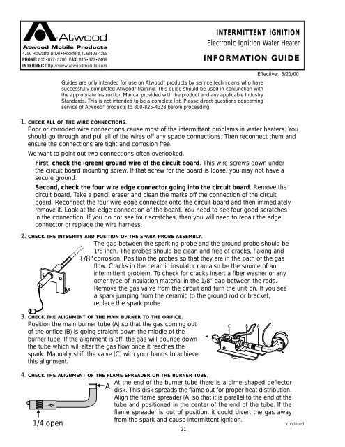
Atwood Water Heater - RV Owner's Manuals
Atwood Water Heater - RV Owner's Manuals
Atwood Water Heater - RV Owner's Manuals

You also want an ePaper? Increase the reach of your titles
YUMPU automatically turns print PDFs into web optimized ePapers that Google loves.
INTERMITTENT IGNITION<br />
Electronic Ignition <strong>Water</strong> <strong>Heater</strong><br />
INFORMATION GUIDE<br />
Guides are only intended for use on <strong>Atwood</strong> ® products by service technicians who have<br />
successfully completed <strong>Atwood</strong> ® training. This guide should be used in conjunction with<br />
the appropriate Instruction Manual provided with the product and any applicable Industry<br />
Standards. This is not intended to be a complete list. Please direct questions concerning<br />
service of <strong>Atwood</strong> ® products to 800-825-4328 before proceeding.<br />
Effective: 8/21/00<br />
1. CHECK ALL OF THE WIRE CONNECTIONS.<br />
Poor or corroded wire connections cause most of the intermittent problems in water heaters. You<br />
should go through and pull all of the wires off any spade connections. Then reconnect them and<br />
ensure the connections are tight and corrosion free.<br />
We want to point out two connections often overlooked.<br />
First, check the (green) ground wire of the circuit board. This wire screws down under<br />
the circuit board mounting screw. If that screw for the board is loose, you may not have a<br />
secure ground.<br />
Second, check the four wire edge connector going into the circuit board. Remove the<br />
circuit board. Take a pencil eraser and clean the marks off the connection of the circuit<br />
board. Reconnect the four wire edge connector onto the circuit board and then immediately<br />
remove it. Look at the edge connection of the board. You need to see four good scratches<br />
in the connection. If you do not see four scratches, then you will need to repair the edge<br />
connector or replace the wire harness.<br />
2. CHECK THE INTEGRITY AND POSITION OF THE SPARK PROBE ASSEMBLY.<br />
The gap between the sparking probe and the ground probe should be<br />
1/8 inch. The probes should be clean and free of cracks, flaking and<br />
1/8" corrosion. Position the probes so that they are in the path of the gas<br />
flow. Cracks in the ceramic insulator can also be the source of an<br />
intermittent problem. To check for cracks insert a fiber washer or any<br />
other type of insulation material in the 1/8” gap between the rods.<br />
Remove the gas valve from the circuit and turn the unit on. If you see<br />
a spark jumping from the ceramic to the ground rod or bracket,<br />
replace the spark probe.<br />
3. CHECK THE ALIGNMENT OF THE MAIN BURNER TO THE ORIFICE.<br />
Position the main burner tube (A) so that the gas coming out<br />
of the orifice (B) is going straight down the middle of the<br />
burner tube. If the alignment is off, the gas will bounce down<br />
the tube which will alter the gas flow once it reaches the<br />
spark. Manually shift the valve (C) with your hands to achieve<br />
this alignment.<br />
C B A<br />
4. CHECK THE ALIGNMENT OF THE FLAME SPREADER ON THE BURNER TUBE.<br />
1/4 open<br />
A<br />
At the end of the burner tube there is a dime-shaped deflector<br />
disk. This disk spreads the flame out for proper heat distribution.<br />
Align the flame spreader (A) so that it is parallel to the end of the<br />
tube and positioned in the center of the end of the tube. If the<br />
flame spreader is out of position, it could divert the gas away<br />
from the spark and cause intermittent ignition.<br />
21<br />
continued