F-Link Inter-Connect Brochure - Optical Cable Corporation
F-Link Inter-Connect Brochure - Optical Cable Corporation
F-Link Inter-Connect Brochure - Optical Cable Corporation
Create successful ePaper yourself
Turn your PDF publications into a flip-book with our unique Google optimized e-Paper software.
F-link inter-connect<br />
F-LINK <strong>Inter</strong>-<strong>Connect</strong> Solution<br />
Overview<br />
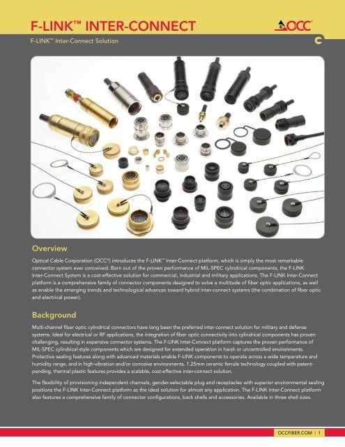
<strong>Optical</strong> <strong>Cable</strong> <strong>Corporation</strong> (OCC ® ) introduces the F-LINK <strong>Inter</strong>-<strong>Connect</strong> platform, which is simply the most remarkable<br />
connector system ever conceived. Born out of the proven performance of MIL-SPEC cylindrical components, the F-LINK<br />
<strong>Inter</strong>-<strong>Connect</strong> System is a cost-effective solution for commercial, industrial and military applications. The F-LINK <strong>Inter</strong>-<strong>Connect</strong><br />
platform is a comprehensive family of connector components designed to solve a multitude of fiber optic applications, as well<br />
as enable the emerging trends and technological advances toward hybrid inter-connect systems (the combination of fiber optic<br />
and electrical power).<br />
Background<br />
Multi-channel fiber optic cylindrical connectors have long been the preferred inter-connect solution for military and defense<br />
systems. Ideal for electrical or RF applications, the integration of fiber optic connectivity into cylindrical components has proven<br />
challenging, resulting in expensive connector systems. The F-LINK <strong>Inter</strong>-<strong>Connect</strong> platform captures the proven performance of<br />
MIL-SPEC cylindrical-style components which are designed for extended operation in harsh or uncontrolled environments.<br />
Protective sealing features along with advanced materials enable F-LINK components to operate across a wide temperature and<br />
humidity range, and in high-vibration and/or corrosive environments. 1.25mm ceramic ferrule technology coupled with patentpending,<br />
thermal plastic features provides a scalable, cost-effective inter-connect solution.<br />
The flexibility of provisioning independent channels, gender-selectable plug and receptacles with superior environmental sealing<br />
positions the F-LINK <strong>Inter</strong>-<strong>Connect</strong> platform as the ideal solution for almost any application. The F-LINK <strong>Inter</strong>-<strong>Connect</strong> platform<br />
also features a comprehensive family of connector configurations, back shells and accessories. Available in three shell sizes.<br />
occfiber.com | 1
F-link inter-connect<br />
Features and Benefits<br />
Features<br />
Maximum Provisioning<br />
Flexibility<br />
B<br />
BLANK HOLE<br />
CONFIGURATION<br />
(DEFAULT)<br />
2<br />
B<br />
ELECTRICAL HOLE BLANK HOLE<br />
CONFIGURATION CONFIGURATION<br />
16 GAGE SOCKET (DEFAULT)<br />
2<br />
1<br />
ELECTRICAL HOLE<br />
FIBER HOLE<br />
CONFIGURATION<br />
CONFIGURATION<br />
16 GAGE SOCKET<br />
Benefits<br />
1<br />
FIBER HOLE<br />
CONFIGURATION<br />
All termini cavities start as<br />
“BLANKS” and are machined to<br />
provide application-specific fiber<br />
optic/electrical B requirements.<br />
B<br />
BLANKS can be machined for<br />
1.25mm F/O Pin or Socket,<br />
16#AWG Copper Pin,<br />
16#AWG Copper Socket<br />
<strong>Inter</strong>changeable Pin/Socket<br />
Insert Caps<br />
END MILL<br />
END MILL<br />
END MILL<br />
F-LINK allows interchangeability<br />
of Pin or Socket insert caps, which<br />
can be provisioned into either<br />
Plug or Receptacle components.<br />
END MILL<br />
Exceptional Environmental<br />
Sealing Capability<br />
A<br />
In-Line Recpt., Male Insert Cap 6 Fiber<br />
THIS DOCUMENT IS THE PROPERTY OF APPLIED OPTICAL SYSTEMS AND CONTAINS PROPRIETARY INFORMATION<br />
AND SHALL NOT BE DISCLOSED TO OTHERS OR DUPLICATED IN PART OR FULL OR USED FOR ANYOTHER PURPOSES<br />
OTHER THAN IN SUPPORT OF OUR VENDOR/PURCHASER RELATIONSHIP<br />
2<br />
A<br />
DRAWN<br />
1700 Capital DRAWN Ave. Suite 50<br />
A<br />
1700 Capital Ave. Suite 50<br />
Raju Penumatcha 3/20/2006<br />
Plano, TX-75074<br />
Raju Penumatcha 3/20/2006<br />
Plano, TX-75074<br />
(972)509-1500<br />
CHECKED<br />
(972)509-1500<br />
www.appliedopticalsystems.com<br />
3/24/2006<br />
CHECKED<br />
www.appliedopticalsystems.com<br />
RMF<br />
3/24/2006<br />
THIRD ANGLE<br />
TITLE<br />
RMF<br />
THIRD ANGLE<br />
TITLE<br />
PROJECTION<br />
APPROVED<br />
APPROVED<br />
rmf<br />
3/24/2006<br />
PROJECTION<br />
Hole Configurations, Insert Cap Socket, F-<strong>Link</strong>, rmf 16 GAGE 3/24/2006<br />
Hole Configurations, Insert Cap Socket, F-<strong>Link</strong>, 16 GAGE<br />
MATERIAL<br />
TOLERANCES<br />
Unless Otherwise Specified<br />
MATERIAL<br />
TOLERANCES<br />
Unless Otherwise Specified<br />
In-Line LINEAR Recpt., ANGULAR Female SIZE DWG Insert NO Cap 6 Fiber REV<br />
LINEAR ANGULAR SIZE DWG NO<br />
REV<br />
HEAT TREATMENT<br />
.X ` .05 X ` 5~<br />
.XX ` .020<br />
A<br />
drill_picture HEAT TREATMENT<br />
.X A ` .05 X ` 5~<br />
X.X ` 1~<br />
.XX ` .020<br />
A<br />
drill_picture<br />
A<br />
.XXX ` .010<br />
SCALE CAGE CODE: 335J8<br />
X.X ` 1~<br />
FINISH<br />
.XXX ` .010<br />
SCALE CAGE CODE: 335J8<br />
THIS DOCUMENT IS THE PROPERTY OF APPLIED All Dimensions OPTICAL SYSTEMS are in AND inches CONTAINS PROPRIETARY DESIGN INFORMATION STATUS FINISH SHEET 1 OF 1<br />
AND SHALL NOT BE DISCLOSED TO OTHERS OR DUPLICATED IN PART OR FULL OR USED FOR ANYOTHER PURPOSES<br />
All Dimensions are inches<br />
DO NOT SCALE DRAWING<br />
Released<br />
DESIGN STATUS<br />
Four sealing surfaces,<br />
SHEET 1 OF 1<br />
OTHER THAN IN SUPPORT OF OUR VENDOR/PURCHASER RELATIONSHIP<br />
DO NOT SCALE DRAWING<br />
Released<br />
1<br />
2<br />
1<br />
including Insert Cap,<br />
Insert Body, Plug and<br />
Receptacle Body and<br />
Rear <strong>Cable</strong> Seal, provide<br />
IP-68 compliance.<br />
A<br />
Versatile, Retractable<br />
Backshell System<br />
The Backshell System is<br />
common to both fiber optic and<br />
composite cable (fiber optic &<br />
electrical).<br />
<strong>Cable</strong> Retention<br />
System – Extended<br />
<strong>Cable</strong> Retention<br />
System – Retracted<br />
The F-LINK Backshell System<br />
provides ease of termination,<br />
allowing extension & retraction of<br />
the inner <strong>Cable</strong> Retention System.<br />
<strong>Inter</strong>changeable Fiber Optic<br />
or Composite Hybrid <strong>Cable</strong><br />
Retention System<br />
Supports either fiber optic cable<br />
or composite hybrid cable<br />
by replacement of the <strong>Cable</strong><br />
Retention System for either fiber<br />
optic or hybrid-style cables.<br />
<strong>Cable</strong> Retention<br />
System – Fiber<br />
Optic Style <strong>Cable</strong><br />
<strong>Cable</strong> Retention<br />
System – Composite<br />
Style <strong>Cable</strong><br />
F-<strong>Link</strong> Termini and<br />
Electrical Pin/Socket Contacts<br />
1.25mm ceramic ferrules are<br />
used within the F-LINK fiber<br />
optic termini. Electrical contacts<br />
are based on the same proven<br />
technology used in D38999<br />
connectors. Insertion/extraction<br />
tools are common and low cost.<br />
2 | occfiber.com
F-link inter-connect<br />
<strong>Connect</strong>or Configurations<br />
SS16, Plug, Male w/Backshell, F/O <strong>Cable</strong> SS16, Panel Mount Receptacle, Male SS16, In-Line Receptacle, Female<br />
SS16, Jam-Nut Receptacle, <strong>Inter</strong>nal, Female SS16, Panel Mount Plug, Female SS16, Backshell for Composite <strong>Cable</strong><br />
SS22, Plug, Male w/Backshell, F/O <strong>Cable</strong> SS22, Jam-Nut Receptacle, <strong>Inter</strong>nal, Female SS22, Jam-Nut Receptacle, External, Male<br />
SS28, Plug, Female w/Backshell,<br />
Fiber Optic <strong>Cable</strong><br />
SS28, Plug, Female w/Backshell, F/O <strong>Cable</strong>,<br />
Dust Cap, Brass<br />
SS28, Panel Mount Receptacle, Female<br />
occfiber.com | 3
F-link inter-connect<br />
Performance Specifications<br />
DRAFT<br />
Performance Specification<br />
EIA/TIA-455-107 -50dB – Typical, -40dB – Maximum<br />
PERFORMANCE SPECIFICATION PARAMETER<br />
Insertion Loss (multimode) EIA/TIA-455-171 0.50dB – Typical, 0.75dB – Maximum<br />
Insertion Loss (single-mode) EIA/TIA-455-171 0.40dB – Typical, 0.75dB – Maximum<br />
Back Reflection<br />
(single-mode UPC polish)<br />
Operating Temperature TIA/EIA-455-5 -40° C to + 85° C<br />
Storage Temperature TIA/EIA-455-5 -40° C to + 85° C<br />
Mating Durability TIA-455-21 500 cycles<br />
Impact TIA/EIA-455-2 Method B , Omit wall pipe<br />
Twist TIA-455-36 ±90° rotation, one cycle/5sec., 1000 cycles<br />
<strong>Cable</strong> Sealing Flex EIA/TIA-455-1 Procedure I<br />
<strong>Cable</strong> Retention 1 TIA-455-6 400 lbs. min.<br />
Crush Resistance TIA-455-26 450 lbs.<br />
Temperature Life TIA/EIA-455-4 250 hrs., 85 ± 2°C<br />
Thermal Shock TIA-455-71 Condition B-0 except 10 cycles, @ 85° C and -62° C<br />
Physical Shock EIA/TIA-455-11 Condition C, 5 shocks/axis<br />
Vibration TIA-455-1 Condition III & VI Condition C for 1.5 hr, Except III<br />
Humidity EIA/TIA-455-5 Type II<br />
Water Submersion IP-68, IEC-60529 1M Depth, 48 Hours. Bulkhead mounted in watertight cube<br />
Ordering Information<br />
NOTES<br />
1<br />
Uses military tactical cable for test purposes<br />
F-LINK SHELL SIZE 16 (6 CHANNEL)<br />
PART NUMBER CONFIGURATION DESCRIPTION<br />
HDANNNNNBU30B Plug, w/Backshell 6 CH (Blank 1 ), Plug, Male, Backshell, Blk. Anodized, 0.240–0.269” <strong>Cable</strong> O.D.<br />
HDBNNNNNBU30B Plug, w/Backshell 6 CH (Blank 1 ), Plug, Female, Backshell, Blk. Anodized, 0.240–0.269” <strong>Cable</strong> O.D.<br />
HDANNNNNBU30D Plug, w/Backshell 6 CH (Blank 1 ), Plug, Male, Backshell, Blk. Anodized, 0.316–0.345” <strong>Cable</strong> O.D.<br />
HDBNNNNNBU30D Plug, w/Backshell 6 CH (Blank 1 ), Plug, Female, Backshell, Blk. Anodized, 0.316–0.345” <strong>Cable</strong> O.D.<br />
HDCNNNNNBM30B Recpt., In-Line w/Backshell 6 CH (Blank 1 ), In-Line Recpt., Male, Backshell, Blk. Anodized, 0.240–0.269” <strong>Cable</strong> O.D<br />
HDDNNNNNBM30B Recpt., In-Line w/Backshell 6 CH (Blank 1 ), In-Line Recpt., Female, Backshell, Blk. Anodized, 0.240–0.269” <strong>Cable</strong> O.D.<br />
HDCNNNNNBM30D Recpt., In-Line w/Backshell 6 CH (Blank 1 ), In-Line Recpt., Male, Backshell, Blk. Anodized, 0.316–0.345” <strong>Cable</strong> O.D.<br />
HDDNNNNNBM30D Recpt., In-Line w/Backshell 6 CH (Blank 1 ), In-Line Recpt., Female, Backshell, Blk. Anodized, 0.316–0.345” <strong>Cable</strong> O.D.<br />
HDENNNNNBM00 Recpt., Panel Mount 6 CH (Blank 1 ), Panel Mount Recpt., Male, Blk. Anodized<br />
HDFNNNNNBM00 Recpt., Panel Mount 6 CH (Blank 1 ), Panel Mount Recpt., Female, Blk. Anodized<br />
HDQNNNNNBU00 Plug, Panel Mount 6 CH (Blank 1 ), Panel Mount Plug, Male, Blk. Anodized<br />
HDRNNNNNBU00 Plug, Panel Mount 6 CH (Blank 1 ), Panel Mount Plug, Female, Blk. Anodized<br />
NOTES<br />
1<br />
“Blank” refers to an untapped cavity that can be modified (drilled or molded) to<br />
accommodate fiber optic pin, fiber optic socket, electrical pin or electrical socket.<br />
4 | occfiber.com
F-link inter-connect<br />
Ordering Information<br />
F-LINK SHELL SIZE 16 (6 CHANNEL)<br />
PART NUMBER CONFIGURATION DESCRIPTION<br />
HDSNNNNNBM00 Recpt., Jam-Nut, <strong>Inter</strong>nal 6 CH (Blank 1 ), Jam-Nut Recpt., Male, <strong>Inter</strong>nal, Blk. Anodized, w/o D-Flat<br />
HDTNNNNNBM00 Recpt., Jam-Nut, <strong>Inter</strong>nal 6 CH (Blank 1 ), Jam-Nut Recpt., Female, <strong>Inter</strong>nal, Blk. Anodized, w/o D-Flat<br />
HDUNNNNNBM00 Recpt., Jam-Nut, External 6 CH (Blank 1 ), Jam-Nut Recpt., Male, External, Blk. Anodized, w/o D-Flat<br />
HDVNNNNNBM00 Recpt., Jam-Nut, External 6 CH (Blank 1 ), Jam-Nut Recpt., Female, External, Blk. Anodized, w/o D-Flat<br />
HDJNNNNNB001 Dust Cap SS16, Dust Cover, Metal, Plug, Blk. Anodized<br />
HDJNNNNNH001 Dust Cap SS16, Dust Cover, Plastic, Plug, Blk. Anodized<br />
HDJNNNNNB002 Dust Cap SS16, Dust Cover, Metal, Rcpt., Int. Jam-Nut, Blk. Anodized<br />
HDJNNNNNB003 Dust Cap SS16, Dust Cover, Metal, Rcpt., Ext. Jam-Nut, Blk. Anodized<br />
HDJNNNNNB004 Dust Cap SS16, Dust Cover, Metal, Rcpt., Panel Mount, Blk. Anodized<br />
F-LINK SHELL SIZE 22 (17 CHANNEL)<br />
PART NUMBER CONFIGURATION DESCRIPTION<br />
HGANNNNNB130D Plug, w/Backshell 17 CH (Blank 1 ), Plug, Male, Backshell, Blk. Anodized, 0.316–0.342” <strong>Cable</strong> O.D.<br />
HGBNNNNNB130D Plug, w/Backshell 17 CH (Blank 1 ), Plug, Female, Backshell, Blk. Anodized, 0.316–0.342” <strong>Cable</strong> O.D.<br />
HGANNNNNB130G Plug, w/Backshell 17 CH (Blank 1 ), Plug, Male, Backshell, Blk. Anodized, 0.422–0.462” <strong>Cable</strong> O.D.<br />
HGBNNNNNB130G Plug, w/Backshell 17 CH (Blank 1 ), Plug, Female, Backshell, Blk. Anodized, 0.422–0.462” <strong>Cable</strong> O.D.<br />
HGCNNNNNB130D Recpt., In-Line w/Backshell 17 CH (Blank 1 ), In-Line Recpt., Male, Backshell, Blk. Anodized, 0.316–0.342” <strong>Cable</strong> O.D.<br />
HGDNNNNNB130D Recpt., In-Line w/Backshell 17 CH (Blank 1 ), In-Line Recpt., Female, Backshell, Blk. Anodized, 0.316–0.342” <strong>Cable</strong> O.D.<br />
HGCNNNNNB130G Recpt., In-Line w/Backshell 17 CH (Blank 1 ), In-Line Recpt., Male, Backshell, Blk. Anodized, 0.422–0.462” <strong>Cable</strong> O.D.<br />
HGDNNNNNB130G Recpt., In-Line w/Backshell 17 CH (Blank 1 ), In-Line Recpt., Female, Backshell, Blk. Anodized, 0.422–0.462” <strong>Cable</strong> O.D.<br />
HGENNNNNB100 Recpt., Panel Mount 17 CH (Blank 1 ), Panel Mount Recpt., Male, Blk. Anodized<br />
HGFNNNNNB100 Recpt., Panel Mount 17 CH (Blank 1 ), Panel Mount Recpt., Female, Blk. Anodized<br />
HGQNNNNNB100 Recpt., Jam-Nut, <strong>Inter</strong>nal 17 CH (Blank 1 ), Recpt., Jam-Nut, <strong>Inter</strong>nal, Male, Blk. Anodized<br />
HGRNNNNNB100 Recpt., Jam-Nut, <strong>Inter</strong>nal 17 CH (Blank 1 ), Recpt., Jam-Nut, <strong>Inter</strong>nal, Female, Blk. Anodized<br />
HGGNNNNNB100 Plug, Panel Mount 17 CH (Blank 1 ), Plug, Panel Mount, Male, Blk. Anodized<br />
HGHNNNNNB100 Plug, Panel Mount 17 CH (Blank 1 ), Plug, Panel Mount, Female, Blk. Anodized<br />
HGUNNNNNB100 Plug, Panel Mount 17 CH (Blank 1 ), Plug, Panel Mount, Male, Blk. Anodized<br />
HGVNNNNNB100 Plug, Panel Mount 17 CH (Blank 1 ), Plug, Panel Mount, Female, Blk. Anodized<br />
HGJNNNNNB001 Dust Cap SS22, Dust Cover, Metal, Plug, Blk. Anodized<br />
HGJNNNNNH001 Dust Cap SS22, Dust Cover, Plastic, Plug, Blk. Anodized<br />
HGJNNNNNB002 Dust Cap SS22, Dust Cover, Metal, Recpt., <strong>Inter</strong>nal Jam-Nut, Blk. Anodized<br />
HGJNNNNNB003 Dust Cap SS22, Dust Cover, Metal, Recpt., External Jam-Nut, Blk. Anodized<br />
HDJNNNNNB004 Dust Cap SS16, Dust Cover, Metal, Recpt., Panel Mount, Blk. Anodized<br />
NOTES<br />
1<br />
“Blank” refers to an untapped cavity that can be modified (drilled or molded) to<br />
accommodate fiber optic pin, fiber optic socket, electrical pin or electrical socket.<br />
occfiber.com | 5
F-link inter-connect<br />
Ordering Information<br />
DRAFT<br />
F-LINK SHELL SIZE 28 (33 CHANNEL)<br />
PART NUMBER CONFIGURATION DESCRIPTION<br />
HJANNNNNB130D Plug, w/Backshell 33 CH (Blank 1 ), Plug, Male, Backshell, Blk. Anodized, 0.316–0.342” <strong>Cable</strong> O.D.<br />
HJBNNNNNB130D Plug, w/Backshell 33 CH (Blank 1 ), Plug, Female, Backshell, Blk. Anodized, 0.316–0.342” <strong>Cable</strong> O.D.<br />
HJANNNNNB130K Plug, w/Backshell 33 CH (Blank 1 ), Plug, Male, Backshell, Blk. Anodized, 0.550–0.589” <strong>Cable</strong> O.D.<br />
HJBNNNNNB130K Plug, w/Backshell 33 CH (Blank 1 ), Plug, Female, Backshell, Blk. Anodized, 0.550–0.589” <strong>Cable</strong> O.D.<br />
HJCNNNNNB130D Recpt., In-Line w/Backshell 33 CH (Blank 1 ), In-Line Recpt., Male, Backshell, Blk. Anodized, 0.316–0.342” <strong>Cable</strong> O.D.<br />
HJDNNNNNB130D Recpt., In-Line w/Backshell 33 CH (Blank 1 ), In-Line Recpt., Female, Backshell, Blk. Anodized, 0.316–0.342” <strong>Cable</strong> O.D.<br />
HJCNNNNNB130K Recpt., In-Line w/Backshell 33 CH (Blank 1 ), In-Line Recpt., Male, Backshell, Blk. Anodized, 0.550–0.589” <strong>Cable</strong> O.D.<br />
HJDNNNNNB130K Recpt., In-Line w/Backshell 33 CH (Blank 1 ), In-Line Recpt., Female, Backshell, Blk. Anodized, 0.550–0.589” <strong>Cable</strong> O.D.<br />
HJENNNNNB100 Recpt., Panel Mount 33 CH (Blank 1 ), Panel Mount Recpt., Male, Blk. Anodized<br />
HJFNNNNNB100 Recpt., Panel Mount 33 CH (Blank 1 ), Panel Mount Recpt., Female, Blk. Anodized<br />
HJQNNNNNB100 Recpt., Jam-Nut, <strong>Inter</strong>nal 33 CH (Blank 1 ), Recpt., Jam-Nut, <strong>Inter</strong>nal, Male, Blk. Anodized<br />
HJRNNNNNB100 Recpt., Jam-Nut, <strong>Inter</strong>nal 33 CH (Blank 1 ), Recpt., Jam-Nut, <strong>Inter</strong>nal, Female, Blk. Anodized<br />
HJGNNNNNB100 Plug, Panel Mount 33 CH (Blank 1 ), Plug, Panel Mount, Male, Blk. Anodized<br />
HJHNNNNNB100 Plug, Panel Mount 33 CH (Blank 1 ), Plug, Panel Mount, Female, Blk. Anodized<br />
HJUNNNNNB100 Plug, Panel Mount 33 CH (Blank 1 ), Plug, Panel Mount, Male, Blk. Anodized<br />
HJVNNNNNB100 Plug, Panel Mount 33 CH (Blank 1 ), Plug, Panel Mount, Female, Blk. Anodized<br />
HJJNNNNNB001 Dust Cap SS28, Dust Cover, Metal, Plug, Blk. Anodized<br />
HJJNNNNNH001 Dust Cap SS28, Dust Cover, Plastic, Plug, Blk. Anodized<br />
HJJNNNNNB002 Dust Cap SS28, Dust Cover, Metal, Recpt., Int. Jam-Nut, Blk. Anodized<br />
HJJNNNNNB003 Dust Cap SS28, Dust Cover, Metal, Recpt., Ext. Jam-Nut, Blk. Anodized<br />
HDJNNNNNB004 Dust Cap SS16, Dust Cover, Metal, Recpt., Panel Mount, Blk. Anodized<br />
F-LINK FIBER OPTIC TERMINI AND ELECTRICAL CONTACTS<br />
PART NUMBER CONFIGURATION DESCRIPTION<br />
TP2042DD01 Termini, Fiber Optic Termini, Fiber Optic, Genderless, Pin, 1.25 Ceramic Ferrule, 126µm<br />
UV164016AA Contact, Electrical Contact, Pin, Electrical, 16# AWG<br />
UV165016AA Contact, Electrical Contact, Pin, Electrical, 16# AWG, Long (Ground)<br />
UV164116AA Contact, Electrical Contact, Socket, Electrical, 16# AWG<br />
PA35395-99-01 Crimp Sleeve Crimp Sleeve, Brass, .114 O.D.<br />
NOTES<br />
1<br />
“Blank” refers to an untapped cavity that can be modified (drilled or molded) to<br />
accommodate fiber optic pin, fiber optic socket, electrical pin or electrical socket.<br />
All F-LINK connectors can be utilized in<br />
any pre-terminated turnkey assemblies.<br />
6 | occfiber.com
F-link inter-connect<br />
Provisioning Guidelines<br />
fiber Optic only<br />
1) Select the appropriate Shell Size to accommodate the fiber optic channel count.<br />
2) Select the connector configurations that meet the intent of the application. Most fiber optic applications require male<br />
plugs with BACKSHELL to support connectivity with female receptacles. Receptacles are selected based on internal,<br />
external jam-nut or panel-mount options.<br />
3) Identify the number of termini required to support the fiber count.<br />
4) Apply one (1) crimp sleeve to each terminus when using receptacle configurations without backshells. Receptacles are<br />
typically provisioned with Simplex 2.0mm loose tube fiber optic cable and Simplex connectors (ex: SC, LC, ST, FC) to<br />
form pigtails.<br />
5) See section insert provisioning to specify the hole pattern portion of the final part number by completing the NNNNN<br />
portion of each connector configuration (ex: HJVNNNNNBU00 becomes HJV00024BU00 for a 24 CH fiber optic application).<br />
HYBRID (Combination of Electrical and Fiber Optic)<br />
1) Select the appropriate Shell Size to accommodate the fiber optic and electrical channel count.<br />
2) Select the connector configurations that meet the intent of the application. Most hybrid applications require the source<br />
of electricity to be protected from hazardous shock along the path of inter-connect. F-LINK supports this requirement<br />
through interchangeable pin/socket insert caps as well as in-line receptacles w/backshell and panel-mounted plugs.<br />
3) Receptacles options include in-line internal, external jam-nut, in-line or panel mount and can be provisioned as<br />
female or male to protect from hazardous shock. Backshells are typically used with in-line receptacles.<br />
4) Plug options include standard plug or panel-mounted plug provisioned as female or male to protect from hazardous shock.<br />
Backshells are typically used with plugs.<br />
5) Identify the number of termini required to support the fiber count.<br />
6) Apply one (1) crimp sleeve to each terminus when using receptacle configurations without backshells. Receptacles are<br />
typically provisioned with Simplex 2.0mm loose tube fiber optic cable and Simplex connectors (ex: SC, LC, ST, FC) to<br />
form pigtails.<br />
7) Identify the number of 16#AWG PIN contacts to support male plug or male receptacle configurations.<br />
8) Identify the number of 16#AWG SOCKET contacts to support female plug or female receptacle configurations.<br />
9) For applications greater than 16#AWG, larger gauge wire can be supported by splitting stranded wire between two<br />
16#AWG contacts or with custom F-LINK applications using 10#AWG contacts. Contact OCC Technical Sales person for<br />
additional information.<br />
10) For applications that require ground fault detection, a long pin (UV165016AA) is applied to the center hole of the male insert<br />
body, making first contact with the mating socket (also located in the center hole), prior to full connector engagement.<br />
11) See section insert provisioning to specify the final part number by completing the NNNNN portion of each connector<br />
configuration (ex: HJVNNNNNB100 becomes HJV20324B100 for a 3 electrical + 24 fiber optic with long ground pin).<br />
PLATING OPTIONS<br />
All F-LINK configurations are supplied with BLACK Anodized as standard plating. Additional plating options are available by<br />
designating the 9th digit position of the part number (ex: HDUNNNNNBU00) with a choice of plating /alternate materials as listed:<br />
“A” Electroless Nickel Plating, Mil-C-26074, 3mil(±0.5mil)<br />
“B” Black Anodized, Mil-A-8625 TYPE 2 CLASS 2<br />
“D” 303 Stainless Steel, Passivation per QQ-P-35/ASTMA967<br />
“E” 316 Stainless Steel, Passivation per QQ-P-35/ASTMA967<br />
“G” Naval Brass, C 46400 H02 Half Hard ASTMB 21/B21M<br />
KEYING OPTIONS: All F-LINK plug/receptacles are supplied with KEY 1 mechanical key options. Alternate keying options are<br />
available upon request. Contact your OCC Technical Sales personnel for additional information.<br />
occfiber.com | 7
F-link inter-connect<br />
Insert Arrangement Provisioning Guidelines<br />
INSERT ARRANGEMENT<br />
AND PROVISIONING<br />
The F-LINK family of connectors<br />
features an advanced means of<br />
provisioning fiber optic and hybrid (fiber<br />
optic and electrical) insert arrangements.<br />
All F-LINK pin and socket insert caps<br />
are manufactured as blank, then drilled<br />
or injection molded according to the<br />
desired hole pattern and termini/<br />
contact arrangement. Hole patterns<br />
can be custom drilled for fast prototype<br />
assemblies. Hole patterns and termini/<br />
contact assignment are designated by<br />
the “NNNNN” scheme within the core<br />
part number of any plug or receptacle<br />
configuration (HGDNNNNNB130G).<br />
HOLE PATTERN AND CHANNEL DESIGNATION<br />
Identification of hole patterns and channel designation for each family member is<br />
identified in the following table.<br />
Male Plug,<br />
Shell Size 16 (1–6 CH)<br />
Male Plug,<br />
Shell Size 22 (1–17 CH)<br />
Male Plug, Shell<br />
Size 28 (1–33 CH)<br />
N N N N N<br />
1 0 2 1 2<br />
Electrical Arrangement<br />
N Not Used<br />
F/O CH count<br />
NN Not Used<br />
Female Plug,<br />
Shell Size 16 (1–6 CH)<br />
Female Plug,<br />
Shell Size 22 (1–17 CH)<br />
Female Plug,<br />
Shell Size 28 (1–33 CH)<br />
1 16#AWG w/o Ground<br />
00–33 00–33 F/O<br />
2 16#AWG w/Ground<br />
Electrical CH count<br />
NN<br />
Not Used<br />
00–33 00–33 Elec.<br />
NOTES<br />
(1) If no electrical contacts are necessary, select (N)<br />
for the 1st digit. “1” is selected if no “center<br />
ground” pin/socket are necessary. “2” is<br />
selected if ground detection (Make-Before-<br />
Contact) is required.<br />
(2) Selection of option “2” will place the ground<br />
pin/socket in the center of the PIN or SOCKET<br />
insert body. This will void the use of the Insert<br />
Cap removal tool.<br />
(3) The maximum number of fiber optic contacts<br />
ranges from “00” to “33” (6 for SS#16, 17 for<br />
SS#22 and 33 for SS#28).<br />
(4) The maximum number of electrical contacts<br />
ranges from “00” to “33” (6 for SS#16, 17 for<br />
SS#22 and 33 for SS#28).<br />
(5) Any combination of 33 fiber optic or electrical<br />
contacts/termini can be applicable.<br />
(6) F-LINK can be used as an “all electrical”<br />
connector.<br />
Male Receptacle,<br />
Shell Size 16 (1–6 CH)<br />
Female Receptacle,<br />
Shell Size 16 (1–6 CH)<br />
Male Receptacle,<br />
Shell Size 22 (1–17 CH)<br />
Female Receptacle,<br />
Shell Size 22 (1–17 CH)<br />
Male Receptacle,<br />
Shell Size 28 (1–33 CH)<br />
Female Receptacle,<br />
Shell Size 28 (1–33 CH)<br />
Corporate Headquarters<br />
5290 Concourse Drive | Roanoke, VA 24019 | USA<br />
Phone: +1-540-265-0690 | 800-622-7711<br />
Fax: +1-540-265-0724<br />
occfiber.com<br />
8 | occfiber.com<br />
10-2011B


