Pitch Circle Problem 8.17 Construct the profile of a disk cam that ...
Pitch Circle Problem 8.17 Construct the profile of a disk cam that ...
Pitch Circle Problem 8.17 Construct the profile of a disk cam that ...
Create successful ePaper yourself
Turn your PDF publications into a flip-book with our unique Google optimized e-Paper software.
Follower Travel, mm<br />
Displacement, cm<br />
1.5<br />
1.0<br />
0.5<br />
0 1 2 3 4 5 6 7 8 9 10<br />
Cam Rotation Angle<br />
90˚<br />
<strong>Pitch</strong><br />
<strong>Circle</strong><br />
0<br />
1<br />
2<br />
3<br />
4<br />
5<br />
10<br />
9<br />
8<br />
7<br />
6<br />
<strong>Problem</strong> <strong>8.17</strong><br />
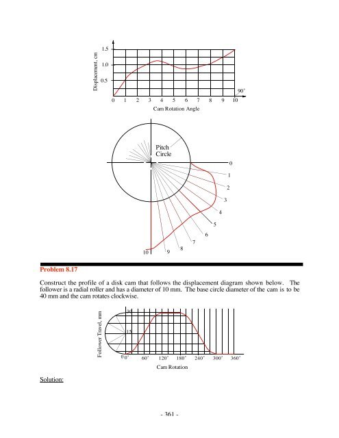
<strong>Construct</strong> <strong>the</strong> <strong>pr<strong>of</strong>ile</strong> <strong>of</strong> a <strong>disk</strong> <strong>cam</strong> <strong>that</strong> follows <strong>the</strong> displacement diagram shown below. The<br />
follower is a radial roller and has a diameter <strong>of</strong> 10 mm. The base circle diameter <strong>of</strong> <strong>the</strong> <strong>cam</strong> is to be<br />
40 mm and <strong>the</strong> <strong>cam</strong> rotates clockwise.<br />
30<br />
15<br />
Solution:<br />
0 0˚ 60˚ 120˚ 180˚ 240˚ 300˚ 360˚<br />
Cam Rotation<br />
- 361 -
Total Follow Travel<br />
Use <strong>the</strong> follower diagram subdivisions <strong>of</strong> 20˚. Next draw <strong>the</strong> <strong>cam</strong> pitch circle and lay <strong>of</strong>f radial<br />
lines in <strong>the</strong> counterclockwise direction. The follower displacements can <strong>the</strong>n be taken directly from<br />
<strong>the</strong> displacement diagram. Draw <strong>the</strong> pitch curve. Draw <strong>the</strong> <strong>cam</strong> follower circles on <strong>the</strong> pitch curve.<br />
Use a smooth curve to draw <strong>the</strong> <strong>cam</strong> <strong>pr<strong>of</strong>ile</strong> tangent to <strong>the</strong> follower circles.<br />
6<br />
5<br />
4<br />
Prime Curve<br />
7<br />
3<br />
8<br />
2<br />
9<br />
Prime <strong>Circle</strong><br />
Base <strong>Circle</strong><br />
1<br />
0<br />
10<br />
Cam<br />
16<br />
17<br />
15<br />
11<br />
12 13<br />
14<br />
<strong>Problem</strong> 8.18<br />
Accurately sketch one half <strong>of</strong> <strong>the</strong> <strong>cam</strong> <strong>pr<strong>of</strong>ile</strong> (stations 0-6) for <strong>the</strong> <strong>cam</strong> follower, base circle, and<br />
displacement diagram given below. The base circle diameter is 1.2 in.<br />
<br />
<br />
1.0<br />
Base <strong>Circle</strong><br />
0 1 2 3 4 5 6 7<br />
11 10 9 8<br />
Station Point<br />
Numbers<br />
- 362 -
220˚<br />
240˚<br />
260˚<br />
280˚<br />
1 inch<br />
300˚<br />
180˚<br />
200˚<br />
Prime circle<br />
320˚<br />
340˚<br />
0˚<br />
80˚<br />
100˚<br />
120˚<br />
<strong>Problem</strong> 8.21<br />
Lay out a <strong>cam</strong> <strong>pr<strong>of</strong>ile</strong> assuming <strong>that</strong> an oscillating, roller follower starts from a dwell for 0˚ to 140˚<br />
<strong>of</strong> <strong>cam</strong> rotation, and <strong>the</strong> <strong>cam</strong> rotates clockwise. The rise occurs with parabolic motion during <strong>the</strong><br />
<strong>cam</strong> rotation from 140˚ to 220˚. The follower <strong>the</strong>n dwells for 40˚ <strong>of</strong> <strong>cam</strong> rotation, and <strong>the</strong> return<br />
occurs with parabolic motion for <strong>the</strong> <strong>cam</strong> rotation from 260˚ to 360˚. The amplitude <strong>of</strong> <strong>the</strong> follower<br />
rotation is 35˚, and <strong>the</strong> follower radius is 1 in. The base circle radius is 2 in, and <strong>the</strong> distance<br />
between <strong>the</strong> <strong>cam</strong> axis and follower rotation axis is 4 in. Lay out <strong>the</strong> <strong>cam</strong> <strong>pr<strong>of</strong>ile</strong> using 20˚ plotting<br />
intervals such <strong>that</strong> <strong>the</strong> pressure angle is 0 when <strong>the</strong> follower is in <strong>the</strong> bottom dwell position.<br />
Solution:<br />
The displacement <strong>pr<strong>of</strong>ile</strong> can be easily computed using <strong>the</strong> equations in Chapter 8 using a<br />
spreadsheet or MATLAB program. Remember <strong>that</strong> <strong>the</strong> parabolic motion is represented by two<br />
curves in each rise and return region. The curves are matched at <strong>the</strong> midpoints <strong>of</strong> <strong>the</strong> rise and<br />
return. The <strong>pr<strong>of</strong>ile</strong> equations are:<br />
For 0 140˚<br />
= 0<br />
For <strong>the</strong> first part <strong>of</strong> <strong>the</strong> rise, 140˚ 180˚ , and<br />
<br />
= 2L<br />
<br />
<br />
<br />
2<br />
where L = 35˚, = 140˚, and = 220˚140˚= 80˚.<br />
For <strong>the</strong> second part <strong>of</strong> <strong>the</strong> rise, 180˚ 220˚ , and<br />
- 367 -
= L 12<br />
1 <br />
<br />
<br />
<br />
2<br />
where L = 35˚, = 140˚, and = 220˚140˚= 80˚.<br />
For 220˚ 260˚<br />
= 35˚<br />
For <strong>the</strong> first part <strong>of</strong> <strong>the</strong> return, 260˚ 310˚, and<br />
<br />
= L 12 <br />
2<br />
<br />
<br />
<br />
<br />
<br />
<br />
where L = 35˚, = 260˚, and = 360˚260˚=100˚<br />
For <strong>the</strong> second part <strong>of</strong> <strong>the</strong> return, 310˚ 360˚, and<br />
= 2L<br />
1 <br />
<br />
2<br />
where L = 35˚, = 260˚, and = 360˚260˚=100˚<br />
The displacement diagram is given below followed by a table <strong>of</strong> values for at 20˚ increments <strong>of</strong><br />
.<br />
Theta Follower Angle<br />
0.000 0.000<br />
20.000 0.000<br />
40.000 0.000<br />
60.000 0.000<br />
80.000 0.000<br />
100.000 0.000<br />
120.000 0.000<br />
140.000 0.000<br />
160.000 4.375<br />
180.000 17.500<br />
200.000 30.625<br />
220.000 35.000<br />
240.000 35.000<br />
260.000 35.000<br />
280.000 32.200<br />
300.000 23.800<br />
- 368 -
320.000 11.200<br />
340.000 2.800<br />
360.000 0.000<br />
To lay out <strong>the</strong> <strong>cam</strong>, first draw <strong>the</strong> prime circle which has a radius <strong>of</strong> 2.0" + 1.0" = 3.0". Next draw<br />
<strong>the</strong> pivot circle for <strong>the</strong> follower pivot. The radius <strong>of</strong> <strong>the</strong> pivot circle is 4". Draw <strong>the</strong> follower in <strong>the</strong><br />
initial position ( = 0˚ ) to determine <strong>the</strong> follower length (r 3 ) and <strong>the</strong> position on <strong>the</strong> pivot circle<br />
corresponding to = 0˚ . As indicated in Example 8.5, <strong>the</strong> length r 3 is given by<br />
r3 = r 1 2 (rb +r0) = 4 2 (2 +1) 2 = 2.646"<br />
Identify <strong>the</strong> point on <strong>the</strong> pivot circle corresponding to = 0˚ , lay <strong>of</strong>f <strong>the</strong> radial lines at 20˚<br />
increments from this point, and label <strong>the</strong> lines in <strong>the</strong> counterclockwise direction. Draw lines from<br />
<strong>the</strong> intersections <strong>of</strong> <strong>the</strong> radal lines with <strong>the</strong> pivot circle tangent to <strong>the</strong> prime circle. Then lay <strong>of</strong>f <strong>the</strong><br />
angular displacements from <strong>the</strong>se tangent lines. Locate <strong>the</strong> center <strong>of</strong> <strong>the</strong> follower by <strong>the</strong> distance r 3<br />
from <strong>the</strong> pivot circle along <strong>the</strong>se lines. Draw 1" radius circles through <strong>the</strong> endponts <strong>of</strong> <strong>the</strong> distances<br />
layed <strong>of</strong>f along <strong>the</strong>se lines, and fit a smooth curve which is tangent to <strong>the</strong> circles corresponding to<br />
<strong>the</strong> roller follower.<br />
The <strong>cam</strong> <strong>pr<strong>of</strong>ile</strong> is shown in <strong>the</strong> following figure.<br />
- 369 -
160˚<br />
140˚<br />
120˚<br />
180˚<br />
100˚<br />
1 inch<br />
200˚<br />
80˚<br />
220˚<br />
60˚<br />
240˚<br />
40˚<br />
260˚<br />
20˚<br />
280˚<br />
0˚<br />
300˚<br />
320˚<br />
340˚<br />
<strong>Problem</strong> 8.22<br />
Lay out <strong>the</strong> rise portion <strong>of</strong> <strong>the</strong> <strong>cam</strong> <strong>pr<strong>of</strong>ile</strong> if a flat-faced, translating, radial follower's motion is<br />
uniform. The total rise is 1.5 in, and <strong>the</strong> rise occurs over 100˚ <strong>of</strong> can rotation. The follower dwells<br />
for 90˚ <strong>of</strong> <strong>cam</strong> rotation prior to <strong>the</strong> beginning <strong>of</strong> <strong>the</strong> rise, and dwells for 80˚ <strong>of</strong> <strong>cam</strong> rotation at <strong>the</strong><br />
end <strong>of</strong> <strong>the</strong> rise. The <strong>cam</strong> will rotate counterclockwise, and <strong>the</strong> base circle radius is 3 in.<br />
Solution:<br />
The displacement <strong>pr<strong>of</strong>ile</strong> can be easily computed using <strong>the</strong> equations in Chapter 8 in a spreadsheet<br />
or MATLAB program. The <strong>pr<strong>of</strong>ile</strong> equations are:<br />
For 0 90˚<br />
s = 0<br />
- 370 -


