Détecteur DAX 420 Infrarouge - Dalemans Gas Detection
Détecteur DAX 420 Infrarouge - Dalemans Gas Detection
Détecteur DAX 420 Infrarouge - Dalemans Gas Detection

Create successful ePaper yourself
Turn your PDF publications into a flip-book with our unique Google optimized e-Paper software.
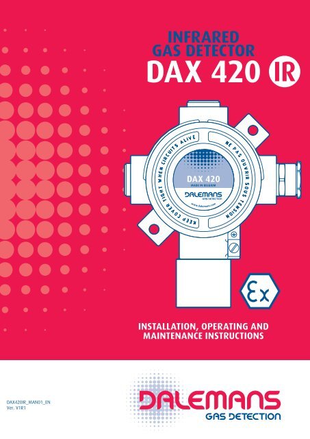
INFRARED<br />
GAS DETECTOR<br />
<strong>DAX</strong> <strong>420</strong><br />
IR<br />
<strong>DAX</strong> <strong>420</strong><br />
MADE IN BELGIUM<br />
www.dalemans.com<br />
INSTALLATION, OPERATING AND<br />
MAINTENANCE INSTRUCTIONS<br />
<br />
Ver. V1R1
1<br />
Introduction<br />
These instructions must be read carefully by any person who has or will have the responsibility for<br />
the installation, the use and/or the maintenance of this equipment. The warranty provided by<br />
DALEMANS will be voided if installation, use and maintenance of this equipment are not in accordance<br />
with the instructions given in this manual.<br />
By respecting these instructions you guarantee the correct operation of the apparatus. Should you<br />
require any further information about the use or the maintenance of this product, do not hesitate<br />
to contact <strong>Dalemans</strong> PRIOR to carrying out installation works.<br />
Each apparatus must be installed, operated and maintained according to the instructions, the<br />
warnings and the operational limits detailed in this manual.<br />
Use only DALEMANS original parts when you assume the maintenance of this product as specified<br />
in this manual. The use of non-<strong>Dalemans</strong> spare parts may seriously impair the performances of the<br />
apparatus. Repair or maintenance attempts carried out without observing the procedures<br />
described in this manual or without the assistance of our after-sales service may prevent the<br />
equipment from working properly and, consequently, from ensuring the safety of the occupants<br />
of the building and of the plants.<br />
!<br />
Application<br />
Always make sure to switch off power and declassify the hazardous area before<br />
carrying out replacement or modification works on components of the gas<br />
detection system.<br />
The <strong>DAX</strong> <strong>420</strong> infrared gas detector is intended for industrial and commercial environment and is<br />
suitable for use in explosive atmospheres of hazardous areas (zone 1 or 2). It is designed to operate<br />
as part of a gas detection system, and to provide, in association with a suitable control unit or<br />
with a Programmable Logic Controller (PLC), early warnings of toxic or flammable gas hazard.<br />
For further information about the detectable gases or the list of compatible control units, please<br />
contact <strong>Dalemans</strong>.<br />
Approval - Standards<br />
As a manufacturer, <strong>Dalemans</strong> Company declares that the products hereby described are certified for<br />
hazardous areas with an ingress protection degree IP6X corresponding to non-aggressive indoor<br />
environments, and that they fulfil the provisions of the following directives and standards :<br />
<br />
<br />
<br />
<br />
<br />
The said products comply with the acceptable variations originating from the type that has received<br />
<br />
<br />
<br />
<strong>DAX</strong> <strong>420</strong><br />
IR
2<br />
Marking<br />
The label below is affixed to the junction box of the detector. This marking applies to the detector<br />
overall assembly. The marking label affixed to the sensing head applies only to the sensing head.<br />
Device Type<br />
ATEX certificate number<br />
Notified Body<br />
identification code<br />
Serial Nr - year of production<br />
Target gas<br />
Measuring range<br />
Operating<br />
temperature range<br />
1026<br />
<strong>DAX</strong> <strong>420</strong><br />
II 2G Ex d IIC T6<br />
II 2D Ex tD A21 IP6X T85°C<br />
Tamb: -20°C to +55°C<br />
FTZU 09 ATEX 0182<br />
<br />
D020AAAM - 91099031 - 2010<br />
<strong>Gas</strong>: CH4<br />
100% LEL<br />
Use: -20..+50°C<br />
IR<br />
Certification (ATEX)<br />
II : non-mining electrical equipment group for potentially explosive atmospheres.<br />
2G : category 2 equipment intended for use in areas where GAS explosive atmospheres<br />
are likely to occur (zone 1).<br />
Ex d : protection by flameproof enclosure “d”.<br />
IIC : equipment group II subdivision according to the nature of the explosive GAS<br />
atmosphere (methane, propane, ethylene, hydrogen, acetylene).<br />
T6 : temperature class according to the maximum surface temperature of the equipment<br />
in explosive GAS atmosphere (T6=85 °C).<br />
2D : category 2 equipment intended for use in areas where DUST explosive atmospheres<br />
are likely to occur (zone 21).<br />
Ex tD : dust ignition protection by enclosure “tD”.<br />
A21 : method of determining the maximum surface temperature of equipment (with 5<br />
mm layer of dust) for use in areas where an explosive atmosphere of combustible<br />
DUST is likely to occur, occasionally, in normal operation (method A - zone 21).<br />
IP6X : dust tight ingress protection.<br />
T85 °C : maximum surface temperature of the equipment for DUST explosive atmospheres.<br />
Tamb : ambient temperature range according to the rated temperature class and the<br />
maximum surface temperature (Tamb = -20 °C to +55 °C for T6 and T85 °C).<br />
<strong>DAX</strong> <strong>420</strong><br />
IR
3<br />
Description<br />
The <strong>DAX</strong> <strong>420</strong> infrared gas detector is designed to detect the presence of toxic gas or to measure<br />
infrared<br />
<br />
<br />
Programmable Logic Controller (PLC) through a 3-wire current loop.<br />
<br />
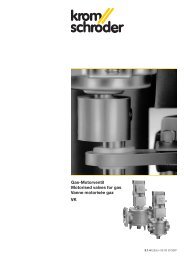
The main parts of the <strong>DAX</strong> <strong>420</strong> infrared gas detector are :<br />
<br />
<br />
<br />
The overall assembly has a flameproof “d” type of protection and an ingress protection IP6X.<br />
Flameproof “d”<br />
junction box<br />
Terminal block<br />
Flameproof “d”<br />
cable gland<br />
4..20 mA<br />
transmitter<br />
“Fault” LED<br />
Wall mounting bracket<br />
Flameproof “d”<br />
sensing head<br />
Figure 1 : <strong>DAX</strong> <strong>420</strong> infrared detector<br />
<strong>DAX</strong> <strong>420</strong><br />
IR
4<br />
Sensing head<br />
The infrared sensor operates according to the Non Dispersive InfraRed principle (NDIR). The sensor<br />
comprises a sample chamber, an infrared light source (lamp) and a wavelength infrared detector.<br />
When a gas diffuses into the sample chamber it absorbs a portion of the infrared radiation of the<br />
lamp. The amount of infrared radiation absorbed by the gas is proportional to the gas concentration.<br />
The wavelength infrared detector measures the unabsorbed infrared radiation and deliver an output<br />
signal which is a function of the gas concentration in the ambient air.<br />
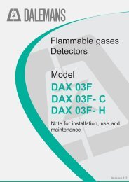
The sensing head of the <strong>DAX</strong> <strong>420</strong> infrared consists of :<br />
<br />
<br />
<br />
<br />
The sensor housing is a stainless steel assembly (body and top) which can be dismantled to allow<br />
plug-in sensor or sintered metal filter replacement.<br />
Top<br />
Sensor sleeve<br />
Sintered metal<br />
filter<br />
Infrared sensor<br />
Body<br />
Figure 2 : Sensing head<br />
<strong>DAX</strong> <strong>420</strong><br />
IR
5<br />
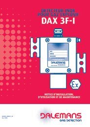
Dimensions<br />
65<br />
145<br />
60<br />
8<br />
65<br />
<strong>DAX</strong> <strong>420</strong><br />
MADE IN BELGIUM<br />
170<br />
www.dalemans.com<br />
105<br />
115<br />
Figure 3 : Mechanical pattern<br />
<strong>DAX</strong> <strong>420</strong><br />
IR
6<br />
Caution<br />
Ensure that local or national regulations relating to the site or the monitored plant are met. The<br />
operator must have knowledge of the safety procedure to follow in case of gas alarm.<br />
Modification, disassembling and total or partial destruction of the sensing head and its contents,<br />
of the cable gland or of the junction box and its contents, may invalidate the essential safety<br />
requirements of the whole plant. No additional drilling is allowed on the junction box. The existing<br />
openings cannot be enlarged. No additional terminal can be installed on the existing terminal<br />
block. The length of the wires of the sensing head may not be modified. Possible defective parts<br />
must be replaced by original parts delivered by <strong>Dalemans</strong> only.<br />
Do not open the junction box or the sensing head while explosion hazard might be present. Only<br />
clean or wipe the detector surface with a wet cloth so as to avoid the risk of electrostatic sparks.<br />
The detector must be protected from any risk of mechanical impact.<br />
Flammable limits and setpoints<br />
<br />
<br />
of flammable limits. Examples include :<br />
<br />
H <br />
<br />
<br />
2<br />
H 6<br />
<br />
<br />
2<br />
H <br />
<br />
<br />
<br />
<br />
5<br />
H 12<br />
<br />
3<br />
H <br />
<br />
<br />
<br />
<br />
The LEL of a gas is affected by temperature and pressure. When the ambient temperature increases,<br />
the LEL decreases and the explosion hazard is higher. The relationship between LEL and pressure is<br />
very complex. However, a pressure increase usually lowers the LEL. The LEL of a gas is not significantly<br />
affected by the humidity fluctuations that may normally occur in the average industrial<br />
environment.<br />
Installation and commissioning<br />
Installation and commissioning must be carried out by the manufacturer or his local representative.<br />
All the operations described hereafter can be carried out only by specialized personnel who<br />
will have been trained beforehand exclusively by <strong>Dalemans</strong>.<br />
<strong>Gas</strong> detection equipment should be installed as late as possible in any program of construction<br />
operations (i.e. construction of a new plant, refitting or maintenance) but before the presence of gas<br />
or vapours in the system, so as to avoid damage to sensors resulting in particular from such activities<br />
as welding and painting. If already installed, sensors should be protected by an airtight seal to avoid<br />
contamination during construction works, and should be clearly marked as being non-operational.<br />
Please follow the recommendations hereafter so as to avoid premature ageing of the detector and<br />
to guarantee its optimal operation. These recommendations are general directives. Always refer<br />
to local regulations/standards in force before proceeding with installation works (i.e. standards<br />
<br />
the recommendations of the manufacturer.<br />
<strong>DAX</strong> <strong>420</strong><br />
IR
7<br />
Location<br />
Detectors must be placed so that potential gas accumulations are detected before they create a<br />
significant hazard. Inappropriate location of a detector can nullify the effect and the integrity of<br />
the gas detection system. The placement of the detectors should be determined in consultation<br />
with experts having specialist knowledge of gas dispersion, with those who have knowledge of<br />
process plant system and equipment involved, and with safety and engineering personnel. Should<br />
you require any further guidance or assistance please contact <strong>Dalemans</strong>.<br />
Detectors should be readily accessible to permit regular calibration, maintenance and electrical<br />
safety inspection. It must be possible to access and fit all accessories or test equipment needed for<br />
these operations on the detector. The location of every detector must be recorded and available to<br />
the safety personnel. The following points should be taken into account when selecting locations to<br />
install the gas detector :<br />
<br />
<br />
<br />
<br />
<br />
<br />
<br />
<br />
<br />
<br />
the detector at a high level.<br />
the detector at a low level.<br />
<br />
<br />
Examples of placement for some flammable gases * :<br />
<strong>Gas</strong> Formula Density (air=1) Detector(s) position<br />
Acetylene (CH) 2<br />
<br />
Butane C <br />
H <br />
Floor<br />
Ethylene oxide C 2<br />
H <br />
O 1.52 Floor<br />
Cracked gas - Ceiling<br />
Isobutane (CH 3<br />
) 3<br />
CH Floor<br />
Methane CH <br />
Ceiling<br />
Natural gas - Ceiling<br />
Propane C 3<br />
H <br />
1.56 Floor<br />
Propane-air - ±1.15 <br />
* This list is not exhaustive. Contact <strong>Dalemans</strong> for further information.<br />
<strong>DAX</strong> <strong>420</strong><br />
IR
8<br />
Mounting<br />
The detector should be mounted flat on a wall and according to the mechanical pattern given on<br />
figure 3. Always use the original wall mounting bracket supplied with the detector. Attach the<br />
detector to the wall using suitable screws and plugs. The sensing head should never be installed<br />
pointing upwards. Make sure that dust will not block the filter and that water will not run into the<br />
sensing head.<br />
Electrical wiring<br />
Wiring must comply with local regulations and standards in force and meet the electrical requirements<br />
of the <strong>DAX</strong> <strong>420</strong> infrared gas detector. <strong>Dalemans</strong> recommends the use of colour coded cable<br />
with solid wires . The acceptable cross sectional area of the cable is<br />
<br />
the control unit/PLC. For more information about the cross sectional area of the cable and the<br />
maximum cable length, please refer to the instruction manual of the control unit/PLC. The overall<br />
The junction box may be earthed<br />
through the cable shield. The cable shield must be connected to the ground at the control unit/<br />
PLC. The cable gland must be sufficiently tightened on the cable to ensure a good sealing.<br />
8 mm MAX<br />
6.1 mm<br />
-<br />
11.7 mm<br />
0.75 - 2.5 mm²<br />
Other size<br />
upon request<br />
15 mm 100 mm<br />
Figure 4 : Cable stripping<br />
Cable length<br />
The <strong>DAX</strong> <strong>420</strong> infrared<br />
properly. Voltages outside this range give a failure warning on “Fault” LED (see figure 1).<br />
The maximum acceptable cable length to connect the detector to the control unit/PLC depends on :<br />
<br />
<br />
The table below and the graph of figure 5 give examples of maximum cable length according to the<br />
cross sectional area of the cable and according to the supply voltage level at the control unit/PLC. For<br />
further information please contact <strong>Dalemans</strong>.<br />
Cable cross sectional area<br />
Max. cable length<br />
V+ = 20 Vdc V+ = 24 Vdc<br />
<br />
<br />
<br />
<strong>DAX</strong> <strong>420</strong><br />
IR
Maximum cable length (m)<br />
1000<br />
900<br />
800<br />
700<br />
600<br />
500<br />
400<br />
300<br />
200<br />
100<br />
2.5 mm²<br />
1.5 mm²<br />
0.75 mm²<br />
Operating range<br />
9<br />
10 15 20 25 30<br />
Supply voltage V+ (Vdc)<br />
Figure 5 : Max. cable length<br />
To connect the detector :<br />
<br />
completely turn the cover counterclockwise to unscrew it.<br />
<br />
plugged so that the gap between insulation and the metallic edge of the terminal connection<br />
does not exceed 1 mm distance.<br />
<br />
<br />
<br />
<br />
+ 24 V<br />
4..20 mA<br />
Output<br />
S<br />
<br />
Plug-in connector<br />
APC Terminal block<br />
0 V<br />
-<br />
Connections for<br />
equipotential bonding<br />
<strong>DAX</strong> <strong>420</strong><br />
IR<br />
Figure 6 : Electrical connection
10<br />
Connection to a <strong>Dalemans</strong> control unit<br />
The connection of the <strong>DAX</strong> <strong>420</strong> infrared detector to a <strong>Dalemans</strong> control unit requires a 3-wire current<br />
loop. Electrical connection must be made with respect to polarity between the <strong>DAX</strong> <strong>420</strong> infrared<br />
detector and the control unit. For instructions about the electrical connection of the control unit, refer<br />
to the original equipment instruction manual.<br />
<strong>DAX</strong> <strong>420</strong> infrared<br />
MIN 19 Vdc<br />
+<br />
-<br />
S<br />
V+<br />
0 V<br />
+<br />
-<br />
(+24 Vdc)<br />
4..20 mA<br />
Input<br />
DALEMANS<br />
control unit<br />
Figure 7 : <strong>Dalemans</strong> control unit<br />
Connection to a Programmable Logic Controller (PLC)<br />
For instructions about the electrical connection of the PLC, please refer to the original equipment<br />
<br />
Ensure that the polarity of the <strong>DAX</strong> <strong>420</strong> infrared output signal meet the polarity of the PLC input.<br />
Put a measuring resistor on the PLC input. Choose the resistor value according to the input scale. The<br />
resistor must have a power rating of min. 1 Watt.<br />
Example :<br />
<br />
R Measure =<br />
5<br />
0.02<br />
= 250 ohms<br />
<strong>DAX</strong> <strong>420</strong> infrared<br />
MIN 19 Vdc<br />
+<br />
-<br />
S<br />
R Measure<br />
V+ (24 Vdc)<br />
0 V<br />
0-5 V<br />
Signal<br />
PLC<br />
Stabilized<br />
power supply<br />
0 V<br />
MIN. 1 Watt<br />
Figure 8 : PLC<br />
<strong>DAX</strong> <strong>420</strong><br />
IR
11<br />
Maintenance<br />
Regularly remove dust from the sensing head and the junction box with a wet cloth ONLY so as to<br />
limit the risk of electrostatic sparks.<br />
The sintered metal filter must be checked and cleaned at least once a year. If contamination of the<br />
filter by solvent, gas or gas vapour has occurred, the sensing head must be replaced and the<br />
inspection interval should be reduced by a factor of 2.<br />
<strong>Gas</strong> detection equipment must be calibrated at least once a year, in some cases three or four times<br />
a year, or even more to mitigate the loss of sensitivity of the sensor. This calibration must be<br />
performed according to the procedure given by the manufacturer or his local representative, and<br />
in any case by qualified personnel who will have been trained by <strong>Dalemans</strong>.<br />
WARNING! Declassify hazardous area PRIOR to operating maintenance, calibration<br />
or service works and check with a portable apparatus that no gas is present<br />
in the atmosphere.<br />
Sintered metal filter replacement<br />
<br />
<br />
<br />
<br />
<br />
<br />
<br />
<br />
<br />
<br />
Sensing head replacement<br />
Prior to replacing the detector sensing head, inhibit the safety function of the detector on the gas<br />
detection system and secure any output device connected to the system to prevent unintended<br />
actuations and false alarms.<br />
<br />
<br />
<br />
<br />
<br />
<br />
<br />
<br />
<br />
<br />
<br />
<br />
<br />
<br />
<br />
- RED on terminal A<br />
- BLUE on terminal P<br />
- WHITE on terminal C<br />
<br />
<br />
<br />
<strong>DAX</strong> <strong>420</strong><br />
IR
12<br />
Troubleshooting<br />
<br />
<br />
<br />
<br />
<br />
<br />
<br />
<br />
The detector measure is either too high or too low :<br />
<br />
The detector gives a null measure although gas is present in the atmosphere :<br />
<br />
<br />
<br />
Spare parts<br />
<br />
<br />
Instruction manual<br />
Junction box - Ex d<br />
Key for locking screw (1.5 mm hex key)<br />
<br />
Screw for locking the cover of junction box<br />
2<br />
<br />
<br />
<br />
<br />
Sensor DIR-CO 2<br />
<br />
Sensor DIR-B (butane)<br />
Sensor DIR-M (methane)<br />
Sensor DIR-P (propane)<br />
Sensor sleeve<br />
Sintered metal filter<br />
Spanner for top of sensing head<br />
<br />
<br />
Article code<br />
<br />
<br />
<br />
<br />
<br />
<br />
<br />
<br />
<br />
<br />
<br />
<br />
<br />
<br />
<br />
<br />
<br />
<br />
<br />
<br />
<strong>DAX</strong> <strong>420</strong><br />
IR
13<br />
Specifications<br />
MODEL<br />
<strong>DAX</strong> <strong>420</strong> infrared<br />
Sensing head<br />
Sintered metal filter<br />
<br />
Junction box<br />
Aluminium<br />
Dimensions / Weight<br />
<br />
Sensor type / Signal<br />
<br />
Adjustments<br />
Zero and calibration by internal potentiometers<br />
Measuring range *<br />
Butane (C <br />
H <br />
)<br />
Methane (CH <br />
)<br />
<br />
Propane (C 3<br />
H <br />
)<br />
Carbon dioxide (CO 2<br />
)<br />
<br />
Resolution<br />
<br />
<br />
<br />
<br />
Expected operating life span <br />
Electrical characteristics<br />
<br />
Storage temperature<br />
<br />
Operating conditions<br />
Temperature range<br />
<br />
Ambient humidity<br />
<br />
Cable cross sectional area <br />
Max. cable length<br />
<br />
Loop resistor<br />
<br />
Ingress protection<br />
IP6X (dust tight)<br />
Cable entries<br />
<br />
Hazardous areas<br />
Zones 1 or 2 (gas) - Zones 21 or 22 (dust)<br />
Equipment gas grouping<br />
IIC (methane, propane, ethylene, hydrogen, acetylene)<br />
Standards<br />
<br />
<br />
II 2G Ex d IIC T6<br />
<br />
Ambient temperature<br />
<br />
Certificates<br />
<br />
* Other gases upon request. Contact <strong>Dalemans</strong> for further information.<br />
<strong>DAX</strong> <strong>420</strong><br />
IR
14<br />
Glossary<br />
Ex d : <br />
<br />
parts which can ignite the explosive atmosphere are placed in an enclosure which can withstand the<br />
pressure developed during an internal explosion of an explosive mixture, and which prevents the<br />
transmission of the explosion to the explosive atmosphere surrounding the enclosure.<br />
Ex tD : <br />
<br />
is based on the limitation of the maximum surface temperature of the enclosure and on the restriction<br />
of dust ingress into the enclosure to avoid ignition of a combustible dust layer or cloud.<br />
94/9/EC :<br />
the laws of the member states concerning equipment and protective systems intended for use in<br />
potentially explosive atmospheres.<br />
EN 60079-0 : standard general requirements applying to equipment intended for use in explosive<br />
atmospheres.<br />
EN 60079-1 : standard applying to equipment protected by flameproof enclosure “d” and intended<br />
for use in explosive gas atmospheres.<br />
EN 61241-0 : standard general requirements applying to electrical apparatus intended for use in<br />
the presence of combustible dust.<br />
EN 61241-1 : standard applying to electrical apparatus protected by enclosure “tD” and intended<br />
for use in the presence of combustible dust.<br />
Environment - WEEE Directive<br />
The crossed-out wheelie bin logo on this product indicates that you are held<br />
to respect the regulation in force on the collection and recycling of Waste<br />
Electrical and Electronic Equipment (WEEE).<br />
These provisions are intended to preserve the natural resources used for<br />
manufacturing this product and to avoid the dispersion of substances<br />
potentially harmful for the environment and human health.<br />
Therefore, to dispose of your end-of-life product, you MUST hand it over to a designated collection<br />
point for the recycling of electrical and electronic Equipment. For further information about the<br />
collection points in your area, contact your local city office.<br />
<strong>DAX</strong> <strong>420</strong><br />
IR
OFFICIAL DEALER<br />
DALEMANS s.a.<br />
<br />
<br />
<br />
www.dalemans.com