Surface Mount Technology (SMT) - Hirox-USA
Surface Mount Technology (SMT) - Hirox-USA
Surface Mount Technology (SMT) - Hirox-USA

You also want an ePaper? Increase the reach of your titles
YUMPU automatically turns print PDFs into web optimized ePapers that Google loves.
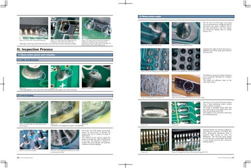
2) Observation angle<br />
With the <strong>Hirox</strong> KH-7700 digital microscope,<br />
you can rotate the lens to change the angle of<br />
observation and acquire a different view of<br />
the same point.(Pictures 162) This rotation<br />
also causes the lighting effect to change.<br />
(Pictures 161)<br />
Picture 150: Errors that occurred during rework. Picture 151: Solder balls that dropped from the<br />
soldering iron tip and burned residual flux<br />
Although a technician performed the tasks, the work has not been checked carefully.<br />
Picture 152: Solder joint on the left side indicates s<br />
oldering with residual solder remaining on the<br />
soldering iron while the solder joint on the right side<br />
shows outcome with a clean soldering iron.<br />
Picture 161: Insufficient hole wetting<br />
Picture 162: Forked soldering iron tip<br />
IV. Inspection Process<br />
1) Observation points and remedies<br />
Changing the angle of observation gives a<br />
different view of the same land. (Pictures<br />
163 and 164)<br />
(1) Voids and blowholes<br />
Picture 163: Good wetting even on 4-layer boards<br />
Picture 164: Re-applied heat from the lead surface<br />
The ability to change the angle of observation<br />
is extremely important for complete<br />
observation.<br />
This allows for different views of the<br />
same land surface.<br />
Picture 153 Picture 154 Picture 155: Blowhole<br />
The small bubbles on the side of the fillet indicate the possibility of a void in the hole.<br />
(2) Land stripping<br />
Picture 165 (enlarged view of picture 141)<br />
Picture 166: Observing solder wetting from the part surface<br />
The holes in the side of the land indicate<br />
that a long preheating phase caused<br />
solder particles to oxidize.<br />
The result is unmelted solder balls that<br />
lost fluidity due to flux deterioration and<br />
were not attracted to the fillet.<br />
This problem can be solved by shortening<br />
the preheating phase.<br />
Picture 156: High solder well temperature causes<br />
land stripping<br />
Picture 157 Picture 158<br />
The land is not stripped, but there is residual flux.<br />
Picture 167 Picture 168<br />
The <strong>Hirox</strong> KH-7700 digital microscope<br />
allows for observation of halation by<br />
rotating the lens to change the angle of<br />
observation.<br />
This method can be used to check the<br />
status of residual flux. (MXG-5040RZ lens)<br />
In this case, the presence or absence or<br />
residual flux also indicates the presence<br />
of absence of land stripping.<br />
Although boards are normally judged by<br />
observing the condition of residual flux,<br />
most observation equipment lacks a<br />
powerful light source to show the<br />
differences. The KH-7700 <strong>Hirox</strong> digital<br />
microscope uses a metal-halide lamp that<br />
is very bright and provides numerous<br />
lighting options.<br />
Picture 159: No land stripping<br />
Picture 160: Land stripping and residual flux are visible<br />
on the bottom of the fillet.<br />
Picture 169<br />
Picture 170: Sample from Picture 169 observed through KH-7700<br />
20 ElectronicPackaging<strong>Technology</strong> ElectronicPackaging<strong>Technology</strong> 21