Surface Mount Technology (SMT) - Hirox-USA
Surface Mount Technology (SMT) - Hirox-USA
Surface Mount Technology (SMT) - Hirox-USA

Create successful ePaper yourself
Turn your PDF publications into a flip-book with our unique Google optimized e-Paper software.
Gas does not bleed well from components<br />
such as aluminum electrolytic capacitors.<br />
Making the lands bigger to facilitate the<br />
release of gas from these parts with<br />
solder convection helps to alleviate this<br />
problem.<br />
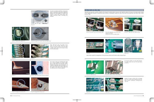
(5) Side balls (on chip side)<br />
Side balls are basically a problem related to the amount of printed solder. However with lead-free solder, the amount of printed solder should<br />
not be significantly reduced, as reductions have an effect on wettability. Instead, the ratio of the land to the opening in the solder mask should<br />
be over 100%.<br />
Picture 86<br />
Picture 95: Side balls from too much printed solder<br />
Picture 96: Image taken using a Rotary-Head<br />
Adapter (MX-5040RZ)<br />
Side balls from excessive solder printing<br />
Picture 97: Solder balls from sudden wicking<br />
Picture 87: Replaced with bigger land<br />
Picture 88: Sample from Picture 87 observed though X-Ray<br />
After 1000 heat cycles, the solder on the<br />
leads has been strongly affected by heat.<br />
However, the effect of heat on the front fillet<br />
is hardly visible, thanks to the release of heat<br />
from the land surface.<br />
Picture 98 Picture 99 Picture 100<br />
Solder balls caused by misalignment of the part lead surface and the land surface (design fault)<br />
Picture 89 Picture 90<br />
The void on the part contacting the lead<br />
has a high possibility of cracked solder<br />
due to heat from the lead that causes<br />
repeated expansion and contraction. It<br />
can be assumed that the land surface and<br />
the voids in the center of the solder are<br />
not affected due to heat dissipation.<br />
b<br />
a<br />
An incorrect profile can cause balls because<br />
the solder cannot wick up to the same place<br />
as the flux.<br />
Picture 91<br />
Picture 92: Heat from the lead is directly transferred<br />
Picture 101: Solder wicking<br />
Picture 99: a. Solder wicking, b. Flux wicking<br />
Instead of trying to resolve this by slowing<br />
down the conveyor belt, speeding up the belt<br />
helps prevent insufficient wicking.(Picture<br />
103,104)<br />
Picture 93 (enlarged view of picture 91) Picture 94 (enlarged view of picture 93)<br />
Picture 103 Picture 104<br />
12 ElectronicPackaging<strong>Technology</strong> ElectronicPackaging<strong>Technology</strong> 13