Ship-Shape Simulation - Ansys
Ship-Shape Simulation - Ansys
Ship-Shape Simulation - Ansys

You also want an ePaper? Increase the reach of your titles
YUMPU automatically turns print PDFs into web optimized ePapers that Google loves.
marine<br />
<strong>Ship</strong>-<strong>Shape</strong> <strong>Simulation</strong><br />
Designers use structural and hydrodynamic analyses to ensure that<br />
working vessels meet challenging demands in harbor and at sea.<br />
By Kuno van den Berg, Project Manager, Gijsbert Jacobse, Marine Engineer<br />
and Michiel Verdult, Marine Engineer, Vuyk Engineering Rotterdam b.v., The Netherlands<br />
Designing ships is a demanding<br />
process, as vessels are among the<br />
most massive and mechanically<br />
complex moving structures in the<br />
world. <strong>Ship</strong>s must operate reliably in<br />
harsh environments and meet<br />
stringent standards. Engineering<br />
demands are particularly challenging<br />
in designing work vessels for harbor<br />
and open-water applications, such as<br />
hoisting, dredging, construction, pipelaying<br />
and other marine operations.<br />
The hull and internal structural<br />
members must be seaworthy and<br />
stable. In addition, topside mechanical<br />
assemblies, such as cranes, must<br />
provide sufficient strength and reliability<br />
to work efficiently even while waves<br />
excite the ship.<br />
In meeting these demanding<br />
requirements, engineers at Vuyk<br />
Engineering Rotterdam (VER) in The<br />
Netherlands rely heavily on engineering<br />
simulation to develop designs and<br />
upgrades, ensure that government<br />
and industry standards are met, and<br />
resolve field problems that may arise.<br />
VER serves the maritime industry<br />
worldwide by providing consultancy<br />
and engineering services for ship<br />
design, equipment design, marine<br />
operations and building supervision.<br />
The company has used ANSYS<br />
Mechanical software exclusively<br />
since 2002 for structural analysis<br />
in determining stress distributions,<br />
elastic deformation, reaction forces<br />
and component fatigue. Engineers<br />
utilize the software for other types of<br />
detailed analysis such as calculation<br />
of structural vibration and impact<br />
loads of one structure colliding with<br />
another. Vuyk chose ANSYS after an<br />
exhaustive evaluation of competitive<br />
packages based on the flexibility of<br />
the code for a range of applications,<br />
recognition of the software globally as<br />
best in class in numerous industries<br />
and depth of the technology for a<br />
broad range of features.<br />
In 2007, VER implemented<br />
ANSYS AQWA software for<br />
computing hydrodynamic<br />
motions and loads on<br />
vessel hulls for strength<br />
and fatigue analyses.<br />
This software can be used to determine<br />
vessel response to wave environmental<br />
conditions. Such capabilities<br />
are required to study critical<br />
operational details such as cargo<br />
swaying as it is lifted, relative<br />
movement of a moored vessel and<br />
interaction of adjacent ships as well as<br />
the ability of the ship to hold a given<br />
position in heavy seas. The capability<br />
to smoothly exchange data between<br />
ANSYS AQWA and ANSYS Mechanical<br />
products is critical in performing<br />
analysis in applications in which<br />
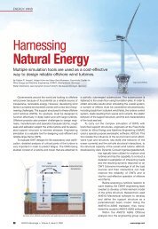
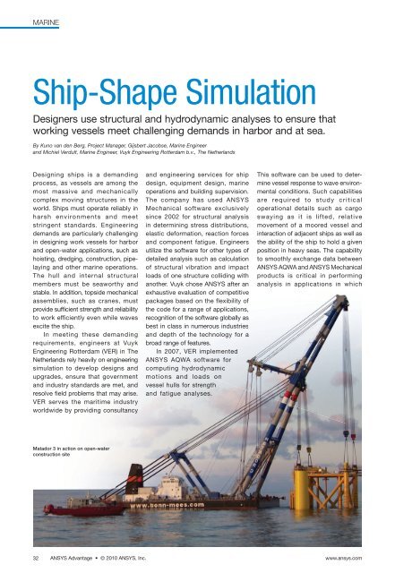
Matador 3 in action on open-water<br />
construction site<br />
32<br />
ANSYS Advantage • © 2010 <strong>Ansys</strong>, Inc.<br />
www.ansys.com
marine<br />
structural behavior is closely related to<br />
hydrodynamic effects.<br />
Prior to licensing ANSYS AQWA,<br />
VER employed rudimentary 2-D strip<br />
theory software. This calculation<br />
method had limitations, as it was only<br />
applicable for a narrow range of<br />
traditional ship hulls and was not suitable<br />
for pure wave-load calculations or<br />
multibody motion analysis. In these<br />
cases, VER outsourced work to an<br />
outside research center or university.<br />
Bringing the work in-house with<br />
ANSYS AQWA technology gives<br />
engineers more control over the hydrodynamic<br />
analysis and greater insight<br />
into vessel behavior. The design team<br />
also can iterate much faster by varying<br />
parameters to compare alternatives<br />
and optimize designs. Performing<br />
time-domain dynamic motion analysis<br />
in-house positions VER among<br />
the leaders in the marine industry<br />
and strengthens the company’s<br />
competitive value as an engineering<br />
services provider.<br />
Upgrading Lifting Capacity<br />
In one recent project, VER<br />
engineers used the ANSYS tools to<br />
upgrade the lifting capacity of the<br />
Matador 3 sheerleg — a self-propelled<br />
floating crane used for lifting heavy<br />
loads at the Rotterdam seaport docks<br />
as well as for offshore construction<br />
projects, open-water wreck removal<br />
operations, and bridge and lock<br />
construction along inland rivers<br />
and canals.<br />
The Matador unit consists of two<br />
hinged, adjustable A-frame structures<br />
with a hoisting jib held in place by a<br />
network of cables looped through<br />
deck sheaves and controlled by main<br />
power winches on the base of a<br />
pontoon platform. One of the larger<br />
floating sheerlegs in the world, the<br />
Matador 3, which is owned and<br />
operated by Bonn & Mees, has a maximum<br />
height and reach of 70 meters.<br />
Two lifting blocks at the top-most<br />
point of each structure are raised and<br />
lowered by cables and winches to lift<br />
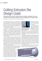
Finite element analysis calculated stress<br />
distribution in the overall Matador 3 lifting<br />
structure (top) as well as individual critical<br />
components such as the sheave support<br />
plates (bottom).<br />
cargo. Alternatively, the A-frame can<br />
be used with four blocks for lifting.<br />
The aim of the redesign project<br />
was to increase the jib lifting capacity<br />
from 600 tonnes to 900 tonnes.<br />
Engineers accomplished this by<br />
increasing the number of sheaves<br />
(pulleys) used on the ship for the<br />
cables to the two jib hoists as well as<br />
sheaves for holding the A-frames in<br />
place. Engineers used ANSYS<br />
Mechanical software to optimize the<br />
jib load capacity by modeling<br />
the lifting frame with beam elements<br />
and calculating reaction forces at the<br />
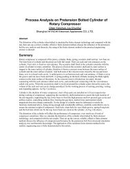
Diffraction analysis calculates the sway and stability of hoisted loads.<br />
hinge points and stresses across all<br />
structural members. By parameterizing<br />
the model, the team was able to<br />
quickly enter different angular<br />
variables to generate lift, reach and<br />
lifting capacity curves for the Matador.<br />
In separate analyses, ANSYS<br />
AQWA was used to study the motions<br />
and loads of the lifting structure<br />
as waves of various heights and<br />
frequencies impact the vessel at<br />
different angles. In these studies, the<br />
vessel and crane structure were<br />
modeled separately from the lifted<br />
structure and then combined with<br />
representations of the connecting<br />
cables into a multibody hydrodynamic<br />
model. The engineering team<br />
determined the working range of<br />
the structure with respect to the<br />
sheerleg capacity and positioning<br />
accuracy.<br />
VER also performed studies for<br />
individual projects in open waters,<br />
including a motion analysis for various<br />
wave scenarios of the Matador during<br />
lifting, transporting and installing<br />
a wind-turbine high-voltage station<br />
in the North Sea. ANSYS AQWA<br />
software was used to determine the<br />
maximum wave height allowable for<br />
various wave periods (time between<br />
wave crests) and headings. using the<br />
simulation from the study, operators<br />
were able to match the ship’s work<br />
schedule to weather forecasts for the<br />
12-hour trip from harbor to the openwater<br />
location to safely transport the<br />
sections of the wind turbine, position<br />
the vessel, and lift the foundation into<br />
place with the platform on top. To<br />
describe the rigorous method of the<br />
www.ansys.com ANSYS Advantage • Volume IV, Issue 2, 2010 33
marine<br />
Joint structural and hydrodynamic analysis determined maximum combined torsion and bending<br />
aft of the hopper.<br />
study to the client, VER cited ANSYS<br />
AQWA capabilities and included the<br />
graphical and tabular output from the<br />
software in the client report.<br />
Upfront <strong>Simulation</strong><br />
In another study, engineers used<br />
ANSYS Mechanical and ANSYS<br />
AQWA software in a one-way coupled<br />
simulation in which hydrodynamic<br />
pressure loads against the outside of<br />
the vessel hull calculated by ANSYS<br />
AQWA software were transferred<br />
directly into ANSYS Mechanical to<br />
determine the structural behavior<br />
of a trailing suction hopper dredging<br />
vessel. In particular, the study was<br />
intended to check longitudinal<br />
bending of the critical midship region<br />
of the hull, calculate overall hull girder<br />
effects at the aft and fore hopper ends,<br />
and provide a detailed stress analysis<br />
for evaluating girder fatigue.<br />
Initially, engineers created a finite<br />
element model for ANSYS Mechanical<br />
using shell elements. The model<br />
included all the major parts of the ship,<br />
such as the outer hull, girders and<br />
basic topside structure. This represented<br />
only the basic geometry and<br />
mass distribution so analysis could<br />
be done in the early stages of basic<br />
vessel design, which takes about five<br />
months to complete. In this way,<br />
results of this upfront simulation could<br />
be used as input for the overall design<br />
of the ship.<br />
A 3-D diffraction analysis was then<br />
performed with ANSYS AQWA soft-<br />
ware to determine the pressure<br />
distribution around the<br />
complete perimeter of the<br />
hull from loads generated<br />
by waves on the side of the<br />
vessel along with associated<br />
vessel motions. The finite element hull<br />
geometry served as the basis for the<br />
diffraction model, ensuring compatibility<br />
between the finite element and<br />
diffraction analyses.<br />
VER engineers combined stillwater<br />
and wave load sets from ANSYS<br />
AQWA into a load set representing<br />
total water pressure against the hull.<br />
This data was then used in ANSYS<br />
Mechanical to determine stress and<br />
buckling of the structural girders. In<br />
this simulation, engineers found a<br />
stress concentration in the main<br />
deck aft of the hopper. Structural<br />
strengthening in this region was<br />
achieved by adding thicker deck plates<br />
and additional girders. A subsequent<br />
fatigue analysis on the modified<br />
structure ensured the validity of the<br />
final design.<br />
Girder analysis of the twin-hull Pieter Schelte<br />
pipelaying vessel, whose unique design<br />
created a number of engineering challenges<br />
In a separate project, coupled simulation<br />
was used in the analysis of the<br />
hull girder design of a unique and very<br />
large twin-bow vessel named Pieter<br />
Schelte, currently in final design and<br />
planned to be the world’s largest pipelaying<br />
vessel. The ship will be about<br />
1,250 feet long and 380 feet wide. Due<br />
to the significant height-to-length ratio<br />
of each bow, traditional rules for ship<br />
design are not applicable for this twinbow<br />
vessel. Thus, the use of ANSYS<br />
AQWA technology was beneficial<br />
because the flexibility of the software<br />
allowed it to be customized. n<br />
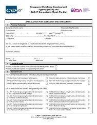
ANSYS Mechanical model of the trailing suction hopper dredger<br />
and longitudinal stresses in the dredger’s midship section<br />
34<br />
ANSYS Advantage • © 2010 <strong>Ansys</strong>, Inc.<br />
www.ansys.com