Ship-Shape Simulation - Ansys
Ship-Shape Simulation - Ansys
Ship-Shape Simulation - Ansys

You also want an ePaper? Increase the reach of your titles
YUMPU automatically turns print PDFs into web optimized ePapers that Google loves.
marine<br />
Joint structural and hydrodynamic analysis determined maximum combined torsion and bending<br />
aft of the hopper.<br />
study to the client, VER cited ANSYS<br />
AQWA capabilities and included the<br />
graphical and tabular output from the<br />
software in the client report.<br />
Upfront <strong>Simulation</strong><br />
In another study, engineers used<br />
ANSYS Mechanical and ANSYS<br />
AQWA software in a one-way coupled<br />
simulation in which hydrodynamic<br />
pressure loads against the outside of<br />
the vessel hull calculated by ANSYS<br />
AQWA software were transferred<br />
directly into ANSYS Mechanical to<br />
determine the structural behavior<br />
of a trailing suction hopper dredging<br />
vessel. In particular, the study was<br />
intended to check longitudinal<br />
bending of the critical midship region<br />
of the hull, calculate overall hull girder<br />
effects at the aft and fore hopper ends,<br />
and provide a detailed stress analysis<br />
for evaluating girder fatigue.<br />
Initially, engineers created a finite<br />
element model for ANSYS Mechanical<br />
using shell elements. The model<br />
included all the major parts of the ship,<br />
such as the outer hull, girders and<br />
basic topside structure. This represented<br />
only the basic geometry and<br />
mass distribution so analysis could<br />
be done in the early stages of basic<br />
vessel design, which takes about five<br />
months to complete. In this way,<br />
results of this upfront simulation could<br />
be used as input for the overall design<br />
of the ship.<br />
A 3-D diffraction analysis was then<br />
performed with ANSYS AQWA soft-<br />
ware to determine the pressure<br />
distribution around the<br />
complete perimeter of the<br />
hull from loads generated<br />
by waves on the side of the<br />
vessel along with associated<br />
vessel motions. The finite element hull<br />
geometry served as the basis for the<br />
diffraction model, ensuring compatibility<br />
between the finite element and<br />
diffraction analyses.<br />
VER engineers combined stillwater<br />
and wave load sets from ANSYS<br />
AQWA into a load set representing<br />
total water pressure against the hull.<br />
This data was then used in ANSYS<br />
Mechanical to determine stress and<br />
buckling of the structural girders. In<br />
this simulation, engineers found a<br />
stress concentration in the main<br />
deck aft of the hopper. Structural<br />
strengthening in this region was<br />
achieved by adding thicker deck plates<br />
and additional girders. A subsequent<br />
fatigue analysis on the modified<br />
structure ensured the validity of the<br />
final design.<br />
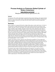
Girder analysis of the twin-hull Pieter Schelte<br />
pipelaying vessel, whose unique design<br />
created a number of engineering challenges<br />
In a separate project, coupled simulation<br />
was used in the analysis of the<br />
hull girder design of a unique and very<br />
large twin-bow vessel named Pieter<br />
Schelte, currently in final design and<br />
planned to be the world’s largest pipelaying<br />
vessel. The ship will be about<br />
1,250 feet long and 380 feet wide. Due<br />
to the significant height-to-length ratio<br />
of each bow, traditional rules for ship<br />
design are not applicable for this twinbow<br />
vessel. Thus, the use of ANSYS<br />
AQWA technology was beneficial<br />
because the flexibility of the software<br />
allowed it to be customized. n<br />
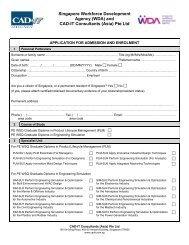
ANSYS Mechanical model of the trailing suction hopper dredger<br />
and longitudinal stresses in the dredger’s midship section<br />
34<br />
ANSYS Advantage • © 2010 <strong>Ansys</strong>, Inc.<br />
www.ansys.com