Create successful ePaper yourself
Turn your PDF publications into a flip-book with our unique Google optimized e-Paper software.
【0-0】<br />
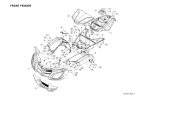
FOREWORD/INDEX
FOREWORD/INDEX<br />
<strong>DINLI</strong> <strong>700</strong> <strong>cc</strong> <strong>Service</strong> <strong>Manual</strong><br />
All rights reserved. No parts of this publication may be reproduced, stored in a retrieval system, or<br />
transmitted in any form or by any means, electronic mechanical photocopying, recording or otherwise,<br />
without the prior written permission of Dinli Metal Industrial Co., Ltd..<br />
No liability can be a<strong>cc</strong>epted for any ina<strong>cc</strong>uracies or omissions in this publication, although every possible<br />
care has been taken to make it as complete and a<strong>cc</strong>urate as possible.<br />
The right is reserved to make changes at any time without prior notice and without incurring an<br />
obligation to make such changes to products manufactured previously. See your dealer for the latest<br />
information on product improvements incorporated after this publication.<br />
All information contained in this publication is based on the latest product information available at the<br />
time of publication.<br />
Illustrations and photographs in this publication are intended for reference use only and may not depict<br />
actual model component parts.<br />
○,CCOPYRIGHT <strong>DINLI</strong> METAL INDUSTRIAL CO., LTD. 2008<br />
【0-1】
FOREWORD/INDEX<br />
Foreword<br />
This manual is designed primarily for use by trained mechanics in a properly equipped shop. A basic<br />
knowledge of mechanics, the proper use of tools, and workshop procedures must be understood in order to<br />
carry out maintenance and repair satisfactorily. In order to perform the work efficiently and to avoid costly<br />
mistakes, read the text thoroughly to familiarize yourself with the procedures before starting work, and then<br />
do the work carefully in a clean area. Precision measurements can only be made if the proper instruments<br />
are used, and the use of substitute tools may adversely affect safe operation.<br />
For the duration of the warranty period, we recommend that all repairs and scheduled maintenance be<br />
performed in a<strong>cc</strong>ordance with this service manual. Any owner maintenance or repair procedure not<br />
performed in a<strong>cc</strong>ordance with this manual may void the warranty.<br />
To get the longest life out of your vehicle:<br />
● Follow the Periodic Maintenance Chart in the <strong>Service</strong> <strong>Manual</strong>.<br />
● Be alert for problems and non-scheduled maintenance.<br />
● Use proper tools and genuine <strong>DINLI</strong> vehicle parts. Genuine parts provided as spare parts are listed in the<br />
Parts Catalog.<br />
● Follow the procedures in this manual carefully. Don’t take shortcuts.<br />
● Remember to keep complete records of maintenance and repair with dates and any replaced parts.<br />
How to Use This <strong>Manual</strong><br />
In preparing this manual, we divided the product into its major systems. These systems became the manual’s<br />
chapters. All information for a particular system from adjustment through disassembly and inspection is<br />
located in a single chapter.<br />
The Quick Reference Guide shows you all of the product’s system and assists in location of their chapters.<br />
Each chapter in turn has its own comprehensive Table of Contents.<br />
The Periodic Maintenance Chart is located in the General Information chapter. The chart gives a time<br />
schedule for required maintenance operations.<br />
If you want spark plug information, for example, go to the Periodic Maintenance Chart first. The chart tells<br />
you how frequently to clean and gap the plug. Next, use the Quick Reference Guide to locate the Electrical<br />
System chapter. Then, use the Table of Contents on the first page of the chapter to find the Spark Plug<br />
section.<br />
【0-2】
FOREWORD/INDEX<br />
Whenever you see these WARNING and CAUTION symbols, heed their instructions! Always follow safe<br />
operating and maintenance practices.<br />
WARNING<br />
This warning symbol identifies special instructions or procedures, which if not correctly<br />
followed, could result in personal injury, or loss of life.<br />
CAUTION<br />
This caution symbol identifies special instructions or procedures, which if not strictly<br />
observed, could result in damage to or destruction of equipment.<br />
This manual contains four more symbols (in addition to WARNING and CAUTION), which will help you<br />
distinguish different types of information.<br />
NOTE<br />
○ This note symbol indicates points of particular interest for more efficient and convenient operation.<br />
● Indicates a procedural step or work to be done.<br />
○ Indicates a procedural sub-step or how to do the work of the procedural step it follows. It also precedes the<br />
text of a NOTE.<br />
Indicates a conditional step or what action to take based on the results of the test or inspection in the<br />
procedural step or sub-step it follows.<br />
【0-3】
FOREWORD/INDEX<br />
CHAPTER INDEX<br />
CHAPTER 1<br />
CHAPTER 2<br />
CHAPTER 3<br />
CHAPTER 4<br />
CHAPTER 5<br />
CHAPTER 6<br />
CHAPTER 7<br />
CHAPTER 8<br />
GENERAL<br />
WHEELS/TIRES<br />
BRAKE<br />
SUSPENSION<br />
FRAME<br />
ENGINE<br />
ELECTRICAL<br />
APPENDIX<br />
【0-4】
GENERAL INFORMATION<br />
GENERAL INFORMATION<br />
Table of Contents<br />
Before Servicing----------------------------------------------------------------------------------------------1-2<br />
Model Identifications--------------------------------------------------------------------------------------- 1-5<br />
General Specifications---------------------------------------------------------------------------------------1-6<br />
Periodic Maintenance Chart-------------------------------------------------------------------------------1-8<br />
【1-1】
GENERAL INFORMATION<br />
Before Servicing<br />
Before starting to perform an inspection service or carry out a disassembly and reassembly operation on a<br />
quad, read the precautions given below. To facilitate actual operations, notes, illustrations, photographs,<br />
cautions, and detailed descriptions have been included in each chapter wherever necessary. This section<br />
explains the items that require particular attention during the removal and reinstallation or disassembly and<br />
reassembly of general parts.<br />
Especially note the following:<br />
(1) Dirt<br />
Before removal and disassembly, clean the quad. Any dirt entering the engine will shorten the life of the<br />
quad. For the same reason, before installing a new part, clean off any dust or metal fillings.<br />
(2) Battery Ground<br />
Disconnect the ground (-) wire from the battery before performing any disassembly operations on the<br />
quad. This prevents the engine from a<strong>cc</strong>identally turning over while work is being carried out, sparks<br />
from being generated while disconnecting the wires from electrical parts, as well as damage to the<br />
electrical parts themselves. For reinstallation, first connect the positive wire to the positive (+) terminal<br />
of the battery.<br />
(3) Installation, Assembly<br />
Generally, installation or assembly is the reverse of removal or disassembly. However, if installation or<br />
assembly sequence is given in this <strong>Service</strong> <strong>Manual</strong>, follow it. Note parts locations and cable, wire, and<br />
hose routing during removal or disassembly so they can be installed or assembled in the same way. It is<br />
preferable to mark and record the locations and routing whenever possible.<br />
(4) Tightening Sequence<br />
When installing bolts, nuts, or screws for which a tightening sequence is given in this <strong>Service</strong> <strong>Manual</strong>,<br />
make sure to follow the sequence. When installing a part with several bolts, nuts, or screws, start them<br />
all in their holes and tighten them to a snug fit, thus ensuring that the part has been installed in its<br />
proper location. Then, tighten them to the specified torque in the tightening sequence and method<br />
indicated. If tightening sequence instructions are not given, tighten them evenly in a cross pattern.<br />
Conversely, to remove a pat, first loosen all the bolts, nuts, or screws that are retaining the part a<br />
1/4-turn before removing them.<br />
(5) Torque<br />
When torque values are given in this <strong>Service</strong> <strong>Manual</strong>, use them. Either too little or too much torque may<br />
lead to serious damage. Use a good quality, reliable torque wrench.<br />
(6) Force<br />
Common sense should dictate how much force is necessary in assembly and disassembly. If a part<br />
【1-2】
GENERAL INFORMATION<br />
seems especially difficult to remove or install, stop and examine what may be causing the problem.<br />
Whenever tapping is necessary, tap lightly using a wooden or plastic-faced mallet. Use an impact driver<br />
for screws (particularly for the removing screws held by non-permanent locking agent) in order to<br />
avoid damaging the screw heads.<br />
(7) Edges<br />
Watch for sharp edges, as they could cause injury through careless handing, especially during major<br />
engine disassembly and assembly. Use a clean piece of thick cloth when lifting the engine or turning it<br />
over.<br />
(8) High-Flash Point Solvent<br />
A high-Flash point solvent is recommended to reduce fire danger. A commercial solvent commonly<br />
available in North America is standard solvent (generic name). Always follow manufacturer and<br />
container directions regarding the use of any solvent.<br />
(9) Gasket, O-Ring<br />
Replace a gasket or an O-ring with a new part when disassembling. Remove any foreign matter from<br />
the mating surface of the gasket or O-ring to ensure a perfectly smooth surface to prevent oil or<br />
compression leaks.<br />
(10) Liquid Gasket, Locking Agent<br />
Clean and prepare surfaces where liquid gasket or non-permanent locking agent will be used. Apply<br />
them sparingly. Excessive amount may block engine oil passages and cause serious damage.<br />
(11) Press<br />
When using a press or driver to install a part such as a wheel bearing, apply a small amount of oil to the<br />
area where the two parts come in contact to ensure a smooth fit.<br />
(12) Ball Bearing and Needle Bearing<br />
Do not remove a ball bearing or a needle bearing unless it is absolutely necessary. Replace any ball or<br />
needle bearings that were removed with new ones. Install bearings with the manufacturer and size<br />
marks facing out, applying pressure evenly with a suitable driver. Apply force only to the end of the<br />
race that contacts the press fit portion, and press it evenly over the base component.<br />
(13) Oil Seal and Grease Seal<br />
Replace any oil or grease seals that were removed with new ones, as removal generally damages seals.<br />
Oil or grease seals should be pressed into place using a suitable driver, applying a force uniformly to<br />
the end of seal until the face of the seal is even with the end of the hole, unless instructed otherwise.<br />
When pressing in an oil or grease seal, which has manufacturer’s marks, press it in with the marks<br />
facing out.<br />
(14) Cir-clip, Retaining Ring, and Cotter Pin<br />
When installing cir-clips and retaining rings, take care to compress or expand them only enough to<br />
install them and no more. Install the cir-clip with its chamfered side facing load side as well. Replace<br />
【1-3】
GENERAL INFORMATION<br />
any cir-clips, retaining rings, and cotter pins with new ones, as removal weakens and deforms them,<br />
they could become detached while the quad is driven, leading to a major problem.<br />
(15) Lubrication<br />
Engine wear is generally at its maximum while the engine is warming up and before all the sliding<br />
surfaces have an adequate lubrication film. During assembly, make sure to apply oil to any sliding<br />
surface or bearing that has been cleaned. Old grease or dirty oil could have lost its lubrication quality<br />
and may contain forging particles that act as abrasives; therefore, make sure to wipe it off and apply<br />
fresh grease or oil. Some oils and greases in particular should be used only in certain applications and<br />
may be harmful if used in an application for which they are not intended.<br />
(16) Direction of Engine Rotation<br />
To rotate the crankshaft manually, make sure to do so in the direction of positive rotation Positive<br />
rotation is counterclockwise as viewed from the left side of the engine. To carry out proper adjustment,<br />
it is furthermore necessary to rotate the engine in the direction of positive rotation as well.<br />
(17) Replacement Parts<br />
When there is a replacement instruction, replace these parts with new ones every time they are removed.<br />
Always replace these parts with new ones every time they are removed. Although the previously<br />
mentioned gasket, O-ring, ball bearing, needle bearing, grease seal, oil seal, cir-clip, and cotter pin have<br />
not been so designated in their respective text, they are replacement parts.<br />
(18) Electrical Wires<br />
All the electrical wires are either one-color or two-color. A two-color wire is identified first by the<br />
primary color and then the stripe color. For example, a yellow wire with thin red stripes is referred to as<br />
a “yellow/red” wire; it would be a “red/yellow” wire if the colors were reversed. Unless instructed<br />
otherwise, electrical wires must be connected to wires of the same color.<br />
(19) Inspection<br />
When parts have been disassembled, visually inspect these parts for the following conditions or other<br />
damage. If there is any doubt as to the condition of them, replace them with new ones.<br />
Abrasion Crack Hardening Warp<br />
Bent Dent Scratch Wear<br />
Color change Deterioration Seizure<br />
(20) Specifications<br />
Specification terms are defined as follows:<br />
“Standards” show dimensions or performances which brand-new parts or systems have.<br />
“<strong>Service</strong> Limits” indicate the usable limits. If the measurement shows excessive wear or deteriorated<br />
performance, replace the damaged parts.<br />
【1-4】
GENERAL INFORMATION<br />
Model Identification<br />
Engine serial number<br />
Vehicle identification number<br />
ENGINE SERIAL NUMBER (Ex. 15M18XXXXX)<br />
VEHICLE IDENTIFICATION (ex. RFWAK85CX6Txxxxxx)<br />
Whenever corresponding with <strong>DINLI</strong> about a particular issue, the engine number and serial number are<br />
important for vehicle identification.<br />
【1-5】
GENERAL INFORMATION<br />
General Specification<br />
NOTE:<br />
Specifications subject to change without notice.<br />
Model<br />
DL702<br />
Engine<br />
Bore and stroke<br />
Compression ratio 10.0:1<br />
Displacement<br />
Coolant system<br />
Coolant<br />
Starting system<br />
Carburetor<br />
Transmission<br />
Final drive<br />
4-stroke, DOHC<br />
102mm x 85 mm<br />
694.6 <strong>cc</strong><br />
Liquid cooled<br />
1:2 water/anti-freeze [ethylene glycol(containing corrosion<br />
inhibitors for aluminum engines and radiators)], Quantity = 3<br />
liter<br />
Electric<br />
Mikuni BSR42<br />
L-H-N-R-P<br />
2WD/4WD/4WD LOCK ; Shaft<br />
Clutch type<br />
Engine idle speed<br />
Spark plug, standard<br />
Spark plug gap<br />
Automatic CVT; wet drum<br />
1300 ± 100 rpm<br />
CR6E (NGK)<br />
0.8~0.9 mm<br />
Lubrication system<br />
Forced pressure and wet sump<br />
Lubricant<br />
4-cycle motorcycle engine oil 10W-40, Grade SF or higher<br />
Ignition system<br />
CDI<br />
Gasoline<br />
Unleaded, Octane 95 or higher<br />
Alternator Output<br />
DC 12V-18A @ 3000rpm<br />
Cooling Device Operating Temperature 85℃<br />
Note: Permissible operating temperature: -10~45。<br />
【1-6】
GENERAL INFORMATION<br />
CHASSIS<br />
Frame<br />
Steel<br />
Overall length<br />
2208 mm<br />
Overall width<br />
1129 mm<br />
Overall height<br />
1120 mm<br />
Seat height<br />
916 mm<br />
Wheel base<br />
1305 mm<br />
Front tire 25 x 8 – 12<br />
Rear tire 25 x 10 – 12<br />
Recommended cold tire pressure (front/rear) 35kpa/ 30kpa (5.0psi/ 4.4psi)<br />
Turning radius 6.5m<br />
Fuse<br />
5A, 10A, 15A, 30A<br />
Loading limit (Incl. rider, cargo, etc….)<br />
250kg<br />
Voltage<br />
12V<br />
Battery<br />
GS, GTX20L-BS<br />
Ground clearance, unloaded<br />
295 mm<br />
Water crossing maximum depth<br />
520 mm<br />
Front suspension travel<br />
170mm<br />
Rear suspension travel<br />
170mm<br />
Dry weight (approx KGs) 298<br />
Fuel tank capacity<br />
20L<br />
Throttle lever free play<br />
3~8 mm<br />
Air filter<br />
Foam<br />
Brake fluid DOT 4<br />
Brake pad thickness (MIN)<br />
3.5 mm<br />
Brake disc thickness (MIN)<br />
4 mm<br />
Drive system<br />
Shaft<br />
【1-7】
GENERAL INFORMATION<br />
Periodic Maintenance Chart<br />
Perform a Pre-Ride inspection before every ride and at schedule maintenance periods.<br />
C=Clean<br />
R=Replace<br />
L=Lubricate<br />
I=Inspect, Verify, Clean, Adjust, Lubricate, Replace if necessary<br />
Items<br />
Interval<br />
Break in<br />
Initial week<br />
Every 1<br />
month<br />
Regular Maintenance Internal<br />
Every 3<br />
month<br />
Every 6 month<br />
First hour<br />
After 10<br />
hours<br />
Every 10 Every 50 Every 100<br />
0 Initial 200 Every 200 Every 1000 Every 2000<br />
Note<br />
WARNING LABELS (condition, readable) Day/Months I I I I I I<br />
Hours<br />
AIR FILTER<br />
km<br />
I C C ★<br />
FRAME (mainframe, subframe) I I I<br />
FUEL LINE I I I Replace every four years<br />
▲ THROTTLE OPERATION I I I I I<br />
SPARK PLUG I Replace every 6000 km<br />
○ IDLE SPEED I I<br />
ENGINE OIL I R R<br />
▲ ENGINE OIL FILTER (s) C R R<br />
DIFFERENTIAL GEAR OIL I Replace every two years<br />
FINAL GEAR OIL I Replace every year<br />
COOLANT I I I Replace every two years<br />
SWITCHES (engine, stop, start, tether, ignition) I I ★<br />
BRAKE FLUID I I I Replace every two years<br />
▲ BRAKE SYSTEM (cables, discs, pads, hosed, etc.) I I I I I ★<br />
BRAKE DISCS I I I I Replace every 10000 km<br />
▲ LIGHTING (headlight, tail light, turning lights) I I<br />
BATTERY (terminals)<br />
I,C<br />
▲ EXHAUST (spark arrester) C<br />
SUSPENSION I I I<br />
NUTS, BOLTS AND FASTENERS I I I I<br />
▲ WHEELS/TIRES (pressure, condition, wear) I I I<br />
▲ Steering assembly (fasteners, operation) I I I I ★<br />
General Lubrication L L L<br />
▲<strong>DINLI</strong> dealer service suggested servicing owners should have the proper tools, service data, and be mechanically qualified.<br />
○Operational safety involved. The service should be performed by a <strong>DINLI</strong> dealer.<br />
★<strong>Service</strong> more frequently if operation in dusty, sandy or snowy area or conditions.<br />
【1-8】
WHEELS/TIRES<br />
Wheels/Tires<br />
Table of Contents<br />
Specifications-----------------------------------------------------------------------------------------------2-2<br />
Wheel Alignment------------------------------------------------------------------------------------------2-3<br />
Steering Centering Inspection---------------------------------------------------------------------2-3<br />
Steering Centering Adjustment-------------------------------------------------------------------2-3<br />
Toe-in Inspection--------------------------------------------------------------------------------------2-4<br />
Toe-in Adjustment------------------------------------------------------------------------------------2-4<br />
Wheels (Rims)----------------------------------------------------------------------------------------------2-5<br />
Wheel Removal----------------------------------------------------------------------------------------2-5<br />
Wheel Installation-------------------------------------------------------------------------------------2-5<br />
Wheel (Rim) Inspection-----------------------------------------------------------------------------2-5<br />
Wheel (Rim) Replacement--------------------------------------------------------------------------2-6<br />
Tires-----------------------------------------------------------------------------------------------------------2-6<br />
Tires Removal----------------------------------------------------------------------------------------2-6<br />
Tires Installation-------------------------------------------------------------------------------------2-7<br />
Tires Inspection--------------------------------------------------------------------------------------2-8<br />
Front Hub---------------------------------------------------------------------------------------------------2-8<br />
Front Hub Removal---------------------------------------------------------------------------------2-8<br />
Front Hub Installation------------------------------------------------------------------------------2-9<br />
Front Hub Disassembly/Assembly-------------------------------------------------------------2-9<br />
Rear Hub---------------------------------------------------------------------------------------------------2-9<br />
Real Hub Installation-----------------------------------------------------------------------------2-9<br />
Rear Hub Disassembly/Assembly-------------------------------------------------------------2-9<br />
【2-1】
WHEELS/TIRES<br />
Specifications<br />
Item<br />
Wheel Alignment: Toe-in<br />
Tires:<br />
Standard tire:<br />
Front<br />
Rear<br />
Tire air pressure (when cold):<br />
Front<br />
Rear<br />
Standard<br />
11~40 mm<br />
AT 25×8-12<br />
MAXXIS M915, Tubeless<br />
AT 25×10-12<br />
MAXXIS M916, Tubeless<br />
35 kPa (0.35 kgf/cm 2 , 5.0 psi)<br />
30 kPa (0.31 kgf/cm 2 , 4.4 psi)<br />
Vehicle Maximum load-capacity<br />
250 KG<br />
【2-2】
WHEELS/TIRES<br />
Wheel Alignment<br />
Toe-in is the amount that the front wheels are closer together in<br />
front than at the rear at the axle height. When there is toe-in, the<br />
distance A (Rear) is the greater than B (Front) as shown.<br />
The purpose of toe-in is to prevent the front wheels from getting<br />
out of parallel at any time, and to prevent any slipping or scuffing<br />
action between the tires and the ground, if toe-in is incorrect, the<br />
front wheels will be dragged along the ground, scuffing and<br />
wearing the tread knobs. Measure the distance between vehicle<br />
center and each wheel. This will tell you which tie rod needs<br />
adjusting.<br />
Caster and camber are secured and required no adjustment.<br />
A (Rear)-B (Front) = Amount of Toe-in<br />
(Distance A and B are measured at axle height)<br />
CAUTION<br />
During the tie rod adjustment, it is very important that the<br />
precautions be taken when tightening tie rod end jam nuts.<br />
Steering Centering Inspection<br />
● Test ride the vehicle.<br />
If the handlebar is straight when the vehicle is traveling in a<br />
straight line, go on to the Toe-in Inspection procedure.<br />
Otherwise, go on to the Steering Centering Adjustment<br />
procedure.<br />
A<br />
Steering Centering Adjustment<br />
● Support the vehicle so that the front wheels are off the ground<br />
and the front axles about the same height as the rear axle.<br />
○ Hold a straight edge [A] against the rear wheel rim on one side<br />
at axle height.<br />
● With the handlebar straight ahead, loosen the locknuts [A] [B]<br />
and Turn the tie-rod adjusting sleeve [C] until the front wheel on<br />
that side is parallel to the straightedge.<br />
A<br />
C<br />
B<br />
NOTE<br />
The locknut [A] on the tie-rod has left-hand threads. Turn the<br />
wrench clockwise for loosening.<br />
CAUTION<br />
Adjust the tie-rod so that the visible thread length [A] is even<br />
on both ends of the tie-rod, or the threads could be damaged.<br />
【2-3】
WHEELS/TIRES<br />
● Repeat the straight edge procedure on the other side of the<br />
vehicle, now the front wheels are parallel to each other and to<br />
the center line of the vehicle.<br />
● Go on to the Toe-in Inspection procedure.<br />
Toe-in Inspection<br />
● Support the vehicle on a stand or the jack so that the front<br />
wheels are off the ground.<br />
● Apply a heavy coat of the chalk near the center of the front tires.<br />
● Using a needle nose scriber, mark a thin mark near the center of<br />
the chalk coating while turning the wheel.<br />
● Keeping the front wheels off the ground, set the handlebar<br />
straight ahead.<br />
●At the level of the axle height, measure the distance between the<br />
scribed lines for both front and rear of the front tires.<br />
● Subtract the measurement of the front from the measurement of<br />
the rear to get the toe-in.<br />
If the toe-in is not in the specified range, go on to the Toe-in<br />
adjustment procedure. Toe-in of Front Wheels Standard:<br />
Standard<br />
0~2 mm<br />
Toe-in Adjustment<br />
● Loosen the locknuts [A] [B] and turn the adjusting sleeves [C]<br />
the same number of turns on both sides to achieve the specified<br />
toe-in.<br />
NOTE<br />
○ The nut [A] on the tie-rod has left-hand threads. Turn the nut<br />
clockwise for loosening.<br />
○ The toe-in will be near the specified value, if the tie-rod<br />
length [D] is 385 mm on each tie-rod.<br />
A<br />
C<br />
B<br />
CAUTION:<br />
Adjust the tie-rod length so that the visible thread length [E]<br />
is even on both ends of the tie-rod. Uneven length could<br />
cause tie-rod damage.<br />
● Check the toe-in.<br />
● Tighten:<br />
Torque - Tie-Rod Adjusting Sleeve Locknuts: 33 N-m (3.4<br />
kgf-m, 45 ft-lb)<br />
● Test ride the vehicle.<br />
【2-4】
WHEELS/TIRES<br />
Wheels (Rims)<br />
Wheel Removal<br />
● Support the vehicle on a stand or the jack so that the wheels are<br />
off the ground.<br />
● Loosen the wheel nuts [A]<br />
● Take off the wheel nuts and remove the wheel.<br />
A<br />
A<br />
Wheel Installation<br />
● Check the tire rotation mark [A] on the tire, and install the wheel<br />
a<strong>cc</strong>ordingly.<br />
NOTE<br />
○ The direction of the tire rotation is shown by an arrow on the<br />
tire sidewall.<br />
● Position the wheel so that the air valve [A] is toward the outside<br />
of the vehicle.<br />
● Tighten the wheel nuts in a criss-cross pattern.<br />
Torque- Wheel Nuts: 52 N-m (5.3 kgf-m, 38 ft-lb )<br />
A<br />
Wheel (Rim) Inspection<br />
● Examine both sides of the rim for dents [A]. If the rim is dented,<br />
replace it.<br />
● If the tire is removed, inspect the air sealing surfaces [A] of the<br />
rim for scratches or nicks. Smooth the sealing surfaces with fine<br />
emery cloth if necessary<br />
【2-5】
WHEELS/TIRES<br />
Wheel (Rim) Replacement<br />
● Remove the wheel (see Wheel Removal)<br />
● Disassemble the tire from the rim (see Tire Removal).<br />
○ Remove the air valve and discard it.<br />
CAUTION:<br />
Replace the air valve whenever the tire is replaced. Do not<br />
reuse the air valve.<br />
● Install a new air valve in the new rim.<br />
A<br />
○ Remove the valve cap, lubricate the stem with a soap and water<br />
solution, and pull the stem [A] through the rim from the inside<br />
out until it snaps into place.<br />
CAUTION:<br />
Do not use engine oil or petroleum distillates to lubricate the<br />
stem because they will deteriorate the rubber.<br />
● Mount the tire on the new rim (see Tire Installation).<br />
● Install the wheel (see Wheel Installation).<br />
TIRES<br />
Tire Removal<br />
● Remove the wheel.<br />
● Unscrew the valve core to deflate the tire.<br />
○ Use a paper valve core tool.<br />
● Lubricate the tire beads and rim flanges on both sides of the<br />
wheel with a soap and water solution, or water. This helps the<br />
tire beads slip off the rim flanges.<br />
A<br />
CAUTION:<br />
Do not lubricate the tire beads and rim flanges with engine<br />
oil or petroleum distillates because they will deteriorate the<br />
tire.<br />
● Remove the tire from the rim using a suitable commercially<br />
available tire changer.<br />
NOTE<br />
○ The tires cannot be removed with hand tools because they fit<br />
the rims tightly.<br />
【2-6】
WHEELS/TIRES<br />
Tire Installation<br />
● Inspect the rim (see Wheel (Rim) Inspection).<br />
● Replace the air valve with a new one.<br />
CAUTION:<br />
Replace the air valve whenever the tire is replaced. Do not<br />
reuse the air valve.<br />
● Check the tire for wear and damage (see Tire Inspection)<br />
● Lubricate the tire beads and rim flanges with a soap and water.<br />
WARNING<br />
Do not use the lubricant other than a water and soap<br />
solution, or water to lubricate the tire beads and rim because<br />
it may cause tire separation.<br />
● Check the tire rotation mark [A] on the tire, and install the tire<br />
on the rim a<strong>cc</strong>ordingly.<br />
○ The tires should be installed on the rims so that each air valve is<br />
toward outside of the vehicle.<br />
NOTE<br />
○ The direction of the tire rotation is shown by an arrow on the<br />
tire sidewall.<br />
● Install the tire on the rim using a suitable commercially available<br />
tire changer.<br />
● Lubricate the tire beads again and center the tire on the rim.<br />
● Support the wheel rim [A] on a suitable stand [B] to prevent the<br />
tire from slipping off.<br />
● Inflate the tire until the tire beads seat on the rim.<br />
WARNING<br />
Do not inflate the tire to more than the maximum tire air<br />
pressure. Over inflation can explode the tire with possibility<br />
of injury and loss of line.<br />
● Check to see that rim lines [A] on both sides of the tire are<br />
parallel with the rim flanges [B].<br />
If the rim lines and the rim flanges are not paralleled, deflate the<br />
tire, lubricate the sealing surfaces again, and re-inflate the tire.<br />
● After the beads are properly seated, check for air leaks.<br />
○ Apply a soap and water solution around the tire bead and check<br />
for bubbles.<br />
● Deflate the tire to the specified pressure.<br />
【2-7】<br />
A<br />
B
WHEELS/TIRES<br />
● Check the tire pressure using an air pressure gauge.<br />
Tire Air Pressure (when cold)<br />
Front:<br />
Rear:<br />
35 kPa (5.0 psi)<br />
30 kPa (4.4 psi)<br />
● Install the wheel (see Wheel Installation).<br />
● Wipe off the soap and water solution on the tire and dry the tire<br />
before operation.<br />
WARNING<br />
Do not operate the vehicle with the water and soap still<br />
around the tire beads. They will cause tire separation, and a<br />
hazardous condition may result.<br />
Tire Inspection<br />
● Examine the tire for damage and wear.<br />
○ If the tire is cut or cracked, replace it.<br />
○ Lumps or high spots on the tread or sidewalls indicate internal<br />
damage requiring tire replacement.<br />
○ Remove any foreign objects from the tread. After removal, check<br />
for leaks with a soap and water solution.<br />
○ Check the shape of the tread knobs. If no vertical side is left on<br />
the drive side of the knobs, replace the tire.<br />
Front Hub<br />
Front Hub Removal<br />
● Remove the wheel (see Wheel Removal).<br />
● Remove the cotter pin<br />
● Remove the caliper by taking off the mounting bolts [A], and let<br />
the caliper hang free.<br />
● Remove the axle nut and pull off the front hub brake disc.<br />
● Separate the brake disc from the front hub.<br />
A<br />
Front Hub Installation<br />
● Grease::<br />
Seal<br />
Front Spindle<br />
● Tighten:<br />
Torque - Front Spindle Nut: 54 N-m (5.5 kgf-m, 40 ft-lb )<br />
● Insert a new cotter pin and bend it over the nut<br />
【2-8】
WHEELS/TIRES<br />
Front Hub Disassembly/Assembly<br />
● Don not press the hub bolts out.<br />
If any hub bolt [A] is damaged, replace the hub [B] and bolts as a<br />
unit.<br />
A<br />
B<br />
Rear Hub<br />
Rear Hub Installation<br />
● Grease the axle spindle.<br />
● Apply non-permanent locking agent: Rear Axle Nuts<br />
● Tighten:<br />
Torque - Rear Axle Nut: 109 N-m (11.0 kgf-m, 80ft-lb)<br />
● Insert a new cotter pin and bend it over the nut.<br />
Rear Hub Disassembly/Assembly<br />
● Do not press the hub bolts out.<br />
If any hub bolt is damaged, replace the hub and bolts as a unit.<br />
【2-9】
BRAKE<br />
BRAKE<br />
Table of Contents<br />
Brake Fluid-----------------------------------------------------------------------------------------------------3-2<br />
Brake Fluid Recommendation----------------------------------------------------------------------3-2<br />
Brake Fluid Level Inspection------------------------------------------------------------------------3-3<br />
Brake Fluid Change------------------------------------------------------------------------------------3-3<br />
Brake Line Air Bleeding------------------------------------------------------------------------------3-4<br />
Master Cylinder----------------------------------------------------------------------------------------------3-5<br />
Master Cylinder Removal----------------------------------------------------------------------------3-5<br />
Master Cylinder Installation-------------------------------------------------------------------------3-5<br />
Calipers---------------------------------------------------------------------------------------------------------3-5<br />
Front Caliper Removal--------------------------------------------------------------------------------3-5<br />
Rear Caliper Removal---------------------------------------------------------------------------------3-6<br />
Caliper Installation------------------------------------------------------------------------------------3-6<br />
Brake Pads-----------------------------------------------------------------------------------------------------3-7<br />
Brake Pads Removal-----------------------------------------------------------------------------------3-7<br />
Brake Pads Installation--------------------------------------------------------------------------------3-7<br />
Brake Pads Wear Inspection-------------------------------------------------------------------------3-7<br />
Brake Discs-----------------------------------------------------------------------------------------------------3-7<br />
Disc Cleaning--------------------------------------------------------------------------------------------3-7<br />
Front Brake Disc Removal---------------------------------------------------------------------------3-8<br />
Rear Brake Disc Removal-----------------------------------------------------------------------------3-8<br />
Front Disc Installation---------------------------------------------------------------------------------3-8<br />
Rear Disc Installation----------------------------------------------------------------------------------3-8<br />
Disc Wear Inspection----------------------------------------------------------------------------------3-8<br />
Disc Runout----------------------------------------------------------------------------------------------3-9<br />
Brake Hoses----------------------------------------------------------------------------------------------------3-9<br />
Brake Hose Inspection--------------------------------------------------------------------------------3-9<br />
Brake Hose Replacement-----------------------------------------------------------------------------3-9<br />
Foot Brake----------------------------------------------------------------------------------------------------3-10<br />
Brake Pedal Position Inspection-------------------------------------------------------------------3-10<br />
Brake Pedal Position Adjustment-----------------------------------------------------------------3-10<br />
Brake Pedal Free Play Inspection-----------------------------------------------------------------3-10<br />
Brake Pedal Removal-------------------------------------------------------------------------------3-10<br />
Brake Pedal Installation-----------------------------------------------------------------------------3-10<br />
Master Cylinder Removal--------------------------------------------------------------------------3-11<br />
Master Cylinder Installation-----------------------------------------------------------------------3-11<br />
【3-1】
BRAKE<br />
Brake Fluid<br />
WARNING<br />
When working with the disc brake, observe the precautions listed below.<br />
1. Never reuse old brake fluid.<br />
2. Do not use fluid from a container that has been left unsealed or that has or that has been open for<br />
a long time.<br />
3. Do not mix two different brands of fluid for use in the brake. This lowers the brake fluid boiling<br />
point and could cause the brake to be ineffective. It may also cause the rubber brake parts to<br />
deteriorate.<br />
4. Don’t leave the reservoir cap off for any length of time to avoid moisture contamination of the<br />
fluid.<br />
5. Don’t change the fluid in the rain or when a strong wind is blowing.<br />
6. Except for the disc pads and disc, use brake fluid, isopropyl alcohol, or ethyl alcohol for cleaning<br />
brake parts. Do not use any other fluid for cleaning these parts. Gasoline, engine oil, or any other<br />
petroleum distillate will cause deterioration of the rubber parts. Oil spilled on any parts will be<br />
difficult to wash off completely and will eventually deteriorate the rubber used in the disc brake.<br />
7. When handing the disc pads or disc, be careful that no disc brake fluid or any oil gets on them.<br />
Clean off any fluid or oil that inadvertently gets on the pads or disc with a high flash-point<br />
solvent. Replace the pads with new ones if they cannot be cleaned satisfactorily.<br />
8. Brake fluid quickly ruins painted surface; any spilled fluid should be completely washed away<br />
immediately.<br />
9. If any of the brake line fittings or the bleed valve is opened at any time, the AIR MUST BE BLED<br />
FROM THE BRAKE LINE.<br />
Brake Fluid Recommendation<br />
Recommended fluid is given in the table below. If none of the recommended fluid is available, use<br />
extra heavy-duty brake fluid only from a container marked DOT 3 or 4.<br />
【3-2】
BRAKE<br />
Brake Fluid Level Inspection<br />
● Position the reservoir horizontal, and check the fluid level in the<br />
reservoir.<br />
If the fluid level is lower than the lower level line, check for fluid<br />
leakage of the brake line, and add the fluid as follow.<br />
○ Removal the reservoir cap, and fill the reservoir to the upper level<br />
line [A] in the reservoir with the same type and brand of the fluid<br />
that is already in the reservoir.<br />
And then install the reservoir cap.<br />
WARNING<br />
Change the fluid in the brake line completely if the fluid must be<br />
refilled but the type and brand of the fluid that is already in the<br />
reservoir are unidentified.<br />
● Tighten:<br />
Torque - Reservoir Cap Screws: 1.5 N-m (0.15 kg-m, 13 in-lb)<br />
Brake Fluid Change<br />
● Remove the reservoir cap and the rubber cap on the bleed valve.<br />
● Attach a clear plastic hose to the bleed valve on the caliper, and<br />
run the other end of the hose into a container.<br />
● Fill the reservoir with new brake fluid.<br />
● Change the brake fluid as follows:<br />
○ Open the bleed valve [D].<br />
○ Squeeze the brake lever and hold it [B].<br />
○ Close the bleed valve [C].<br />
○ Release the brake level [A].<br />
● Check the fluid level in the reservoir often, replenishing it as<br />
necessary.<br />
NOTE<br />
○ If the fluid in the reservoir runs completely out any time during<br />
fluid change, air will enter the line, and the system must be<br />
bled.<br />
B<br />
A<br />
● Repeat this operation until fresh brake fluid comes out into the<br />
plastic hose or the color of the fluid change.<br />
WARNING<br />
Do not mix two brand of fluid. Change the brake fluid in the<br />
brake line completely if the fluid must be refilled but the type and<br />
brand of the brake fluid that is already in the reservoir are<br />
unidentified.<br />
【3-3】
BRAKE<br />
● Tighten:<br />
Torque - Bleed Valve: 5.4 N-m (0.55 kg-m, 48 in-lb)<br />
● Apply the brake lever forcefully for a few second, and check for<br />
fluid leakage around the fittings.<br />
WARNING<br />
If the brake lever has a soft or "spongy feeling" when it is applied,<br />
there might be air in the brake line or the brake may be defective.<br />
Since it is dangerous to operate the vehicle under such condition,<br />
bleed the air from the brake line immediately.<br />
Brake Line Air Bleeding<br />
● Bleed the air whenever brake parts are replaced or reassembled.<br />
● Remove the reservoir cap and fill the reservoir with new brake<br />
fluid.<br />
● Slowly pump the brake lever several times until no air bubbles<br />
can be seen rising up through the fluid from the hose at the<br />
bottom of the reservoir. This bleeds the air from the master<br />
cylinder and the brake line.<br />
NOTE<br />
○Tap the brake hose lightly going from the caliper to the reservoir<br />
side and bleed the air off at the reservoir.<br />
B<br />
A<br />
● Attach a clear plastic hose to the bleed valve on the caliper, and<br />
run the other end of the hose into a container.<br />
● Bleed the brake line and the caliper as follows:<br />
○ Hold the brake level applied [B].<br />
○ Quickly open and close the valve [C].<br />
○ Release the brake lever [A].<br />
● The fluid level must be checked several times during the bleeding<br />
operation and replenished as necessary.<br />
NOTE<br />
○ If the fluid in the reservoir runs completely out any time during<br />
bleeding, the bleeding operation must be done over again from<br />
the beginning since air will have entered the line.<br />
○ If the brake level action still feels soft or "spongy", tap the brake<br />
hose from bottom to top and air will rise up to part of the hose.<br />
Slowly pump the brake level in the same manner as above.<br />
● Tighten:<br />
Torque - Bleed Valves: 5.4 N-m (0.55 kg-m, 48 in-lb)<br />
● Apply the brake lever forcefully for a few seconds, and check for<br />
fluid leakage around the fittings.<br />
【3-4】
BRAKE<br />
Master Cylinder<br />
Master Cylinder Removal<br />
●Removal:<br />
Brake Hose Banjo Bolt [B]<br />
Master Cylinder Clamp Bolts [A]<br />
Master Cylinder<br />
CAUTION<br />
Brake fluid quickly ruins painted surface; any spilled fluid<br />
should be completely washed away immediately.<br />
Master Cylinder Installation<br />
● The master cylinder clamp must be installed with the "UP" mark<br />
[C] upwards.<br />
● Tighten the upper clamp bolt first, and then the lower clamp bolt.<br />
There will be a gap at the lower part of the clamp after tightening.<br />
Torque - Master Cylinder Clamp Bolts:<br />
8.8N-m(0.90kg-m,78in-lb)<br />
● Use a new flat washer on each side of the brake hose fitting, and<br />
tighten the banjo bolt.<br />
Torque - Brake Hose Banjo Bolt:25N-m(2.5kg-m,18.0ft-lb)<br />
● Bleed the brake line after master cylinder installation (see Brake<br />
Line Air Bleeding).<br />
● Check the brake for good braking power and no fluid leakage.<br />
WARNING<br />
Do not attempt to drive the vehicle until a full brake lever is<br />
obtained by pumping the brake lever until the pads are against<br />
each disc. The brakes will not function on the first application of<br />
the lever if this is not done.<br />
Caliper<br />
Front Caliper Removal<br />
●Remove the front wheel (see Wheels/Tires chapter).<br />
●Loosen the banjo bolt [A] at the brake hose lower end, and tighten<br />
it loosely.<br />
●Unscrew the caliper mounting bolts [B], and detach the caliper [C]<br />
from the disc.<br />
●Unscrew the banjo bolt and remove the brake hose [D] from the<br />
caliper.<br />
B<br />
C<br />
D<br />
A<br />
CAUTION<br />
Immediately wash away any brake fluid that spills.<br />
【3-5】
BRAKE<br />
NOTE<br />
○If the caliper is to be disassembled after removal and if<br />
compressed air is not available, disassemble the caliper before<br />
the brake hose is removed (see Caliper Disassembly).<br />
Rear Caliper Removal<br />
●Remove the rear wheel (see Wheels/Tires chapter).<br />
●Remove the exhaust pipe.<br />
●Remove the rear drive shaft.<br />
●Loosen the banjo bolt at the brake hose lower end, and tighten it<br />
loosely.<br />
●Unscrew the caliper mounting bolts, and detach the caliper from<br />
the disc.<br />
●Unscrew the banjo bolt and remove the brake hose from the<br />
caliper.<br />
C<br />
CAUTION<br />
Immediately wash away any brake fluid that spills.<br />
Caliper Installation<br />
● Install the caliper and brake hose lower end.<br />
○ Replace the washers that are on each side of hose fitting with new<br />
ones.<br />
● Tighten:<br />
Torque -Caliper Mounting Bolts:25N-m(2.5kg-m,18.0ft-lb)<br />
Brake Hose Banjo Bolt:25N-m(2.5kg-m,18.0ft-lb)<br />
● Check the fluid level in the brake reservoir.<br />
● Bleed the brake line (see Brake Line Air Bleeding).<br />
● Check the brake for good braking power, no brake drag, and no<br />
fluid leakage.<br />
WARNING<br />
Do not attempt to drive the vehicle until a full brake lever is<br />
obtained by pumping the brake lever until the pads are against<br />
each disc. The brakes will not function on the first application of<br />
the lever if this is not done.<br />
【3-6】
BRAKE<br />
Brake Pads<br />
Brake Pad Removal<br />
● Remove the wheels (see Wheels/Tires chapter).<br />
● Remove the caliper (see Caliper Removal)<br />
● Push the anti-rattle spring [A], remove the pads [B] [C].<br />
Brake Pad Installation<br />
● Push the caliper piston in by hand as far as it will go.<br />
● Be sure that the anti-rattle spring is in place.<br />
● Install the pads<br />
● Tighten:<br />
Torque - Pad Mounting Bolts:18N-m(1.8kg-m,13.0ft-lb)<br />
WARNING<br />
Do not attempt to drive the vehicle until a full brake lever is<br />
obtained by pumping the brake lever until the pads are against<br />
each disc. The brakes will not function on the first application of<br />
the lever if this is not done.<br />
Brake Pad Wear Inspection<br />
● Check the lining thickness [A] of the pads in each caliper.<br />
If the lining thickness of either pad is less than the service limit [B],<br />
replace both pads in the caliper as a set.<br />
Pad Lining Thickness:<br />
Standard: 4.5mm<br />
<strong>Service</strong> Limit: 2mm<br />
Brake Discs<br />
Disc Cleaning<br />
Poor braking can be caused by oil on a disc. Oil on a disc must be<br />
cleaned off with an oil cleaning fluid such as trichloroethylene or<br />
acetone.<br />
WARNING<br />
These cleaning fluids are usually highly flammable and harmful<br />
if breathed for prolonged periods. Be sure to heed the fluid<br />
manufacturer's warnings.<br />
【3-7】
BRAKE<br />
Front Brake Disc Removal<br />
● Remove:<br />
Front Hub (see Wheels/Tires chapter)<br />
Brake Disc Mounting Bolts [A]<br />
Brake Disc [B]<br />
A<br />
Rear Brake Disc Removal<br />
● Remove the rear caliper (see Rear Caliper Removal) and Parking<br />
Brake Caliper, unscrew the banjo bolt and remove the brake hose<br />
from the caliper.<br />
● Loosen the brake disc mounting bolts [A].<br />
● Support the vehicle.<br />
● Remove the rear wheel (see Wheel Removal).<br />
● Remove the disc.<br />
B<br />
A<br />
Front Disc Installation<br />
● The disc must be installed with the marked side [A] facing toward<br />
the steering knuckle.<br />
● Tighten:<br />
Non-permanent Locking Agent - Disc Mounting Bolts<br />
Torque - Disc Mounting Bolts: 37N-m(3.8kg-m,27ft-lb)<br />
● After installing the discs, check the disc runout. Completely clean<br />
off any grease that has gotten on either side of the disc with a<br />
high flash point solvent.<br />
A<br />
Brake Disc Installation<br />
● The disc must be installed with the marked side [A] facing toward<br />
front.<br />
● Tighten:<br />
Non-permanent Locking Agent - Disc Mounting Bolts<br />
Torque - Disc Mounting Bolts: 37N-m(3.8kg-m, 27ft-lb)<br />
● After installing the discs, check the disc runout (see Disc Runout).<br />
Completely clean off any grease that has gotten on either side of<br />
the disc with a high flash point solvent.<br />
● Check the disc wear (see Disc Wear).<br />
A<br />
Disc Wear Inspection<br />
● Measure the thickness of each disc at the point [A] where it has<br />
worn the most.<br />
Replace the disc if has worn past the service limit.<br />
[B] Measuring Area<br />
B<br />
【3-8】
BRAKE<br />
Front Disc Thickness<br />
Standard: 3.5mm<br />
<strong>Service</strong> Limit: 3mm<br />
Rear Disc Thickness<br />
Standard: 4 mm<br />
<strong>Service</strong> Limit: 3.5mm<br />
Disc Runout<br />
● Jack up the vehicle so that the wheels are off the ground.<br />
● Remove the front wheels and turn the handlebar fully to one side.<br />
● Set up a dial gauge against the disc [A], and measure the disc<br />
runout.<br />
If the runout exceeds the service limit, replace the disc.<br />
Disc Runout<br />
Standard: TIR 0.2 mm or less<br />
<strong>Service</strong> Limit: TIR 0.3 mm<br />
A<br />
Brake Hoses<br />
Brake Hose Inspection<br />
●The high pressure inside the brake line can cause fluid to leak or<br />
the hose to burst if the line is not properly maintained. Bend and<br />
twist the brake hose while examining it.<br />
Replace it if any cracks or bulges are noticed.<br />
Brake Hose Replacement<br />
●Pump the brake fluid out of the line as explained in the Brake<br />
Fluid Change.<br />
●Remove the banjo bolts at both ends of the brake hose, and pull<br />
the hose off the vehicle.<br />
●Immediately wipe up any brake fluid that spills.<br />
CAUTION<br />
Brake fluid quickly ruins painted surfaces; any spilled fluid<br />
should be completely washed away immediately.<br />
●Use a new flat washer for each side of the hose fittings.<br />
●Install the new brake hose in its place, and tighten the banjo bolts.<br />
Torque - Brake Hose Banjo Bolts: 25N-m(2.5kg-m,18.0ft-lb)<br />
【3-9】
Foot Brake<br />
BRAKE<br />
Brake Pedal Position Inspection<br />
●Check that the brake pedal [A] is in the correct position as shown.<br />
A<br />
Pedal Position [C]<br />
Standard:<br />
72 ~ 80 mm above footrest<br />
If it is correct, adjust the brake pedal position.<br />
B<br />
C<br />
Brake Pedal Position Adjustment<br />
● Remove the brake pedal (see Brake Pedal Removal).<br />
● Loosen the nut [A], and turn the bracket [B] until pedal is<br />
correctly positioned.<br />
● Tighten the nut [A].<br />
● Check the brake pedal free play (see Brake Pedal Free Play<br />
Inspection).<br />
B<br />
A<br />
Brake Pedal Free Play Inspection<br />
● Check the brake pedal free play [A].<br />
○ Depress the brake pedal lightly by hand until the brake is applied.<br />
If the free play is incorrect, adjust it.<br />
Pedal Free Play<br />
Standard:<br />
2.2 ± 0.5 mm<br />
A<br />
A<br />
Brake Pedal Removal<br />
●Remove:<br />
Cir-clip [B]<br />
Pin [C]<br />
Master Cylinder Joint [A]<br />
C<br />
B<br />
A<br />
●Pulling down the springs (where circled), remove the brake pedal.<br />
Brake Pedal Installation<br />
● Reverse the Removal steps to install the brake pedal.<br />
【3-10】
BRAKE<br />
Master Cylinder Removal<br />
●Remove the master cylinder joint [A] and the banjo bolt [B] at the<br />
brake hose lower end, and tighten it loosely.<br />
●Remove the brake hose [C].<br />
●Loosen the master cylinder mounting bolts [D].<br />
●Remove:<br />
Fastener [A]<br />
Hose [B]<br />
Reservoir [C]<br />
CAUTION<br />
Brake fluid quickly ruins painted surfaces; any spilled fluid<br />
should be completely washed away immediately.<br />
A<br />
D C B<br />
Master Cylinder Installation<br />
● Use a new flat washer on each side of the brake hose fitting, and<br />
tighten the banjo bolt.<br />
Torque -Brake Hose Banjo Bolt: 25N-m(2.5kg-m,18.0ft-lb)<br />
● Check the fluid level [A] in the brake reservoir.<br />
● Bleed the brake line after master cylinder installation (see Brake<br />
Line Air Bleeding).<br />
●Check the brake for good braking power and no fluid leakage.<br />
WARNING<br />
Do not attempt to drive the vehicle until a full brake lever is<br />
obtained by pumping the brake lever until the pads are against<br />
each disc. The brakes will not function on the first application of<br />
the lever if this is not done.<br />
【3-11】
SUSPENSION/STEERING<br />
SUSPENSION & STEERING<br />
Table of Contents<br />
Shock Absorbers----------------------------------------------------------------------------------------------4-2<br />
Front Shock Absorber Removal---------------------------------------------------------------------4-2<br />
Front Shock Absorber Installation-----------------------------------------------------------------4-2<br />
Front Shock Absorber Inspection-------------------------------------------------------------------4-2<br />
Front Shock Absorber Preload Adjustment------------------------------------------------------4-2<br />
Rear Shock Absorber Removal----------------------------------------------------------------------4-2<br />
Rear Shock Absorber Installation------------------------------------------------------------------4-2<br />
Rear Shock Absorber Preload Adjustment ------------------------------------------------------4-3<br />
Suspension Arms---------------------------------------------------------------------------------------------4-3<br />
Suspension Arm Removal----------------------------------------------------------------------------4-3<br />
Suspension Arm Installation------------------------------------------------------------------------4-3<br />
Suspension Arm Disassembly-----------------------------------------------------------------------4-3<br />
Suspension Arm Assembly--------------------------------------------------------------------------4-3<br />
Steering--------------------------------------------------------------------------------------------------------4-4<br />
Steering Stem Removal-------------------------------------------------------------------------------4-4<br />
Steering Stem Installation----------------------------------------------------------------------------4-4<br />
Steering Knuckle Removal---------------------------------------------------------------------------4-5<br />
Steering Knuckle Installation------------------------------------------------------------------------4-5<br />
Tie-Rod Removal---------------------------------------------------------------------------------------4-5<br />
Tie-Rod Installation------------------------------------------------------------------------------------4-6<br />
Tie-Rod End Removal---------------------------------------------------------------------------------4-6<br />
Tie-Rod End Installation------------------------------------------------------------------------------4-6<br />
Steering Maintenance---------------------------------------------------------------------------------------4-6<br />
Steering Inspection-------------------------------------------------------------------------------------4-6<br />
Steering Stem Warp------------------------------------------------------------------------------------4-7<br />
Steering Lubrication-----------------------------------------------------------------------------------4-7<br />
Steering Stem Clamp Inspection-------------------------------------------------------------------4-7<br />
Tie-Rod End and Steering Knuckle Joint Inspection------------------------------------------4-7<br />
Handlebar------------------------------------------------------------------------------------------------------4-8<br />
Handlebar Removal-----------------------------------------------------------------------------------4-8<br />
Handlebar Installation--------------------------------------------------------------------------------4-8<br />
Transmission-------------------------------------------------------------------------------------------------4-8<br />
Differential Gear Oil Inspection--------------------------------------------------------------------4-8<br />
Differential Gear Oil Replacement-----------------------------------------------------------------4-9<br />
Rear Driver Gear Oil Inspection--------------------------------------------------------------------4-9<br />
Rear Driver Gear Oil Replacement----------------------------------------------------------------4-9<br />
【4-1】
Shock Absorbers<br />
SUSPENSION/STEERING<br />
Front Shock Absorber Removal<br />
● While supporting the vehicle up with a jack.<br />
● Remove:<br />
Front Shock Absorber Mounting Bolt and Nut [A]<br />
Front Shock Absorber [B]<br />
Front Shock Absorber Installation<br />
● Insert the shock absorber into the bracket [C].<br />
● Tighten:<br />
Torque - Mounting Bolts and Nuts:<br />
47 N-m (4.8 kgf-m, 35 ft-lb)<br />
● While supporting the vehicle down with a jack.<br />
Front Shock Absorber Inspection<br />
Since the front shock absorbers are sealed units, which cannot be<br />
disassembled, only external checks are necessary.<br />
★ If one unit is damaged, replace both shock absorbers as a set. If<br />
only one unit is replaced and the two are not balanced, vehicle<br />
at high speed may endanger driver’s safety.<br />
A<br />
C<br />
B<br />
Front Shock Absorber Preload Adjustment<br />
The spring adjusting sleeve on rear shock absorber has 5 positions<br />
so that the spring can be adjusted for different terrain and loading<br />
conditions. If the spring action feels too soft or too stiff, adjust it in<br />
a<strong>cc</strong>ordance with the following photograph.<br />
● Turn the adjusting sleeve on shock absorber to the desired<br />
position with the wrench.<br />
Rear Shock Absorber Removal<br />
● Support the vehicle on a stand or a jack so that the rear wheels are<br />
off the ground.<br />
● While holding the rear wheels, remove the lower and upper<br />
shock absorber mounting bolts [A] and nuts.<br />
● Remove the rear shock absorber [B].<br />
Rear Shock Absorber Installation<br />
● Tighten-Torque-Rear Shock Absorber Mounting Nuts:<br />
6.2 N-m (6.3 kgf-m, 46ft.lb)<br />
● See the Front Shock Absorber Preload Adjustment.<br />
A<br />
B<br />
Rear Shock Absorber Preload Adjustment<br />
● See the Front Shock Absorber Preload Adjustment<br />
【4-2】
SUSPENSION/STEERING<br />
Suspension Arms<br />
Suspension Arm Removal<br />
● Remove:<br />
Front Wheel (see Wheels/Tires chapter)<br />
Front Hub (see Wheels/Tires chapter)<br />
Cotter Pin, Nut and Bolt [A]<br />
Tie-Rod End [B]<br />
Front Shock Absorber Mounting Bolts [C]<br />
Suspension Arm Pivot Bolts [D]<br />
C<br />
B<br />
A<br />
Suspension Arm Installation<br />
● Tighten:<br />
Torque –<br />
Suspension Arm Pivot Bolts: 88 N-m (9.0 kgf-m, 65 ft-lb)<br />
Steering Knuckle Joint Nut: 42 N-m (4.3 kgf-m, 31 ft-lb)<br />
A<br />
Suspension Arm Disassembly<br />
● Remove:<br />
Bolts<br />
Caps<br />
Bushings<br />
Spacer<br />
● Holding the suspension arm with a vise, remove the cotter pin[A]<br />
and unscrew the castle nut [B], and then remove the knuckle joint<br />
and circlip.<br />
CAUTION<br />
Do not remove the knuckle joint grease seal. It is packed with<br />
grease.<br />
Suspension Arm Assembly<br />
● When installing the rubber bushing into the arm, lubricate the<br />
outer surface of the bushings with a soap and water solution.<br />
CAUTION<br />
Do not lubricate the rubber bushings with engine oil or<br />
petroleum distillates because they will deteriorate the rubbers.<br />
● Position the bushings in the suspension arm as shown using a<br />
suitable bearing driver in the bearing driver set.<br />
【4-3】
SUSPENSION/STEERING<br />
Steering<br />
Steering Stem Removal<br />
● Remove:<br />
Handlebar Holder Bolts ×2<br />
Handlebar Holder Cover<br />
Upper Handlebar Clamp bolts [A] ×4<br />
Upper Handlebar Clamp<br />
Handlebar (see Handlebar Removal)<br />
Oil Tank Cover(see Frame Chapter)<br />
Instrument Panel<br />
A<br />
● Remove:<br />
Steering Clamp Bolts [A]<br />
Steering Clamp Support Plate [B]<br />
Steering Clamp [C]<br />
Tie-Rod End Nuts [D]<br />
Steering Stem Cotter Pin [E] and Nut [F]<br />
CAUTION<br />
Do not loosen the locknut at the ends of the tie-rod adjusting<br />
sleeve, or the toe-in of the front wheels will be changed.<br />
● To remove the steering stem bearing [G], remove the cotter pin<br />
and nut from the bottom end of the steering stem.<br />
● Pull the steering stem out of the frame.<br />
Steering Stem Installation<br />
● Lubricate the steering stem clamp, grease seals (See Steering<br />
Lubrication).<br />
● Install the grease seals [B] facing the end [A] rearward to prevent<br />
the entry of dirt.<br />
● Install the steering stem clamps on both grease seals, fit into the<br />
groves on the steering stem clamps [C].<br />
【4-4】
● Tighten:<br />
Torque –<br />
Bottom End Nut: 29 N-m (3.0 kgf-m, 22 ft-lb)<br />
Bearing Housing Bolts: 20 N-m (2.0 kgf-m, 14.5 ft-lb)<br />
Clamp Allen Bolts: 25 N-m (2.5 kgf-m, 18.0 ft-lb)<br />
Tie-Rod End Nuts: 47 N-m (4.8 kgf-m, 35 ft-lb)<br />
SUSPENSION/STEERING<br />
● Inspect the toe-in if necessary.<br />
Steering Knuckle Removal<br />
● Remove:<br />
Front wheel and Hub (see Wheels/Tires chapter)<br />
Brake Hose Clamp<br />
Tie-Rod End Nut [A] and Tie-Rod End<br />
D<br />
B<br />
CAUTION<br />
Do not loosen the locknuts at the ends of the tie-rod adjusting<br />
sleeve, or the toe-in of the front wheels will be changed.<br />
C<br />
A<br />
C<br />
● Remove:<br />
Front Shock Absorber Clamp Bolt [B] and Nut<br />
Knuckle Joint Bolt [C] and Nut<br />
Suspension Arm [D]<br />
Steering Knuckle Installation<br />
● Clean the sealing surface [A] and the hole [B].<br />
● Grease the sealing surface.<br />
● Tighten:<br />
Torque –<br />
Suspension Arm Pivot Bolts: 88 N-m (9.0 kgf-m, 65 ft-lb)<br />
Steering Knuckle Joint Nut: 42 N-m (4.3 kgf-m, 35 ft-lb)<br />
Front Shock Absorber Clamp Nut:<br />
52 N-m (5.3 kgf-m, 38 ft-.lb)<br />
Tie-Rod End Nut: 47 N-m (4.8 kgf-m, 35 ft-lb)<br />
Tie-Rod Removal<br />
● Remove:<br />
Tie-Rod End Nuts [A]<br />
Tie-Rod [B]<br />
B<br />
C<br />
CAUTION<br />
When removing the tie-rod, be careful not to bend it. Do not<br />
loosen the locknut [C] at the end of the tie-rod adjusting sleeve,<br />
or the toe-in of the front wheel will be changed.<br />
A<br />
【4-5】
SUSPENSION/STEERING<br />
Tie-Rod Installation<br />
● The right and left tie-rods are identical.<br />
● Install the tie-rod with the flattened area [A] located inboard.<br />
● Tighten:<br />
Torque - Tie-Rod End Nuts: 47 N-m (4.8 kgf-m, 35 ft-lb)<br />
● Inspect the toe-in if necessary<br />
A<br />
Tie-Rod End Removal<br />
● Remove the tie-rod (see Tie-Rod Removal)<br />
● Holding the tie-rod flattened area; loosen the locknut [A] and<br />
unscrews the tie-rod end [B].<br />
NOTE<br />
○The locknut on the tie-rod has left-hand threads. Turn the<br />
wrench clockwise for loosening.<br />
CAUTION<br />
Do not remove the grease seal. It is packed with grease.<br />
Tie-Rod End Installation<br />
● Install the tie-rod ends so that the tie-rod has the correct length<br />
[A], and the both visible thread length [B] make equal.<br />
Tie-Rod Length Standard: 398 mm<br />
● Tighten:<br />
Torque –<br />
Tie-Rod adjusting Sleeve Locknut:<br />
27 N-m (2.8 kgf-m, 20 ft-lb)<br />
Steering Maintenance<br />
Steering Inspection<br />
● Turn the handlebar left and right, and check the steering action.<br />
If the steering is not smooth, or if the steering binds or catches<br />
before the stop, lubricate the steering.<br />
NOTE<br />
○The cables and wires will have some effect on the steering<br />
action which must be taken into a<strong>cc</strong>ount.<br />
● Check the steering action again.<br />
【4-6】
If the steering lubrication does not remedy the problem, inspect<br />
the steering stem warp, steering stem clamps, and tie-rod<br />
bearings.<br />
If you feel looseness, or if the steering rattles as it turns, check the<br />
tightness of the steering bolts and nuts.<br />
● Tighten loose bolts and nuts to the specified torque (see Exploded<br />
View), and check the steering action again.<br />
If the steering action does not change by tightening the bolts and<br />
nuts, inspect the steering stem clamps, steering stem bearing, tierod<br />
bearings, and steering knuckle joints.<br />
SUSPENSION/STEERING<br />
Steering Stem Warp<br />
● Remove the steering stem (see Steering Stem Removal).<br />
● Check the steering stem for straightness.<br />
○ Use a straightedge rule along the stem.<br />
If the steering stem is bent, replace the steering stem.<br />
Steering Lubrication<br />
● Lubricate the steering stem clamps.<br />
○ Remove the steering stem (see Steering Stem Removal).<br />
○ Wipe all the old grease off the steering stem, and clamps, and out<br />
of the grease seals.<br />
○Apply grease to the steering stem [A], grease seal lips and mating<br />
surface [B] of the clamp, and pack the grooves [C] in the clamp<br />
with grease.<br />
Steering Stem Clamp Inspection<br />
● Inspect the steering stem clamps [A].<br />
If roughness, excessive play, or seizure is found, replace both<br />
clamps.<br />
Tie-Rod End and Steering Knuckle Joint Inspection<br />
●Inspect each spherical bearing [A].<br />
If roughness, excessive play, or seizure is found, replace the<br />
tie-rod end, or steering knuckle joint.<br />
If damage, wear or deterioration is found, replace the tie-rod end.<br />
【4-7】
Handlebar<br />
SUSPENSION/STEERING<br />
Handlebar Removal<br />
● Remove:<br />
Throttle Switch<br />
Front Brake Master Cylinder<br />
Left Lever Switch Housing<br />
Right Lever Switch<br />
Handlebar Cover Screw<br />
Handlebar Cover<br />
● Remove:<br />
Handlebar Holder Bolts [A]<br />
Handlebar Holders [B]<br />
Handlebar [C]<br />
A<br />
C<br />
A<br />
B<br />
Handlebar Installation<br />
● Install the handlebar so that the angle of the handlebar matches<br />
the angle of the steering stem as shown.<br />
● Tighten the holder rear bolts first and then the front bolts.<br />
Torque –<br />
Handlebar Holder Bolts: 27 N-m (2.8 kgf-m, 20 ft-lb)<br />
○ If the holder is correctly installed, there will be no gap at the rear<br />
and an even gap at the front after tightening.<br />
Second<br />
First<br />
Transmission<br />
Differential Gear Oil Inspection<br />
NOTE<br />
○ Inspect every 2,000 km ( 100 hours, 6 months). Replace every<br />
2 years.<br />
● Place the vehicle on level ground.<br />
● Remove the oil level plug [1] and oil filler plug [2], and inspect<br />
the oil level. If the oil level is below the level hole, add fresh oil<br />
until oil flows from the level hole.<br />
【4-8】
● Tighten the oil level plug [1] and oil filter plug [2] to the specified<br />
torque.<br />
SUSPENSION/STEERING<br />
Differential Gear Oil Replacement<br />
● Place the vehicle on level ground.<br />
● Remove the front under protector.<br />
● Place an oil pan below the differential gear case.<br />
● Drain oil by removing the oil drain plug [3], oil filter plug [2] and<br />
oil level plug [1].<br />
● Tighten the oil drain plug [3] to the specified torque and pour<br />
fresh oil through the oil filter hole until it overflows from the oil<br />
level hole.<br />
● Tighten the oil level plug [1] and oil filter plug [2] to the specified<br />
torque.<br />
● Install the front under protector.<br />
Differential Gear Oil Specification:<br />
Hypoid gear oil SAE#80, API grade GL-5<br />
Torque –<br />
Front differential gear oil level plug :<br />
9 N-m (0.9 kgf-m, 6.5 ft-lb)<br />
Front differential gear oil drain plug :<br />
32 N-m (3.2 kgf-m, 23.0 ft-lb)<br />
Front differential gear oil filler plug :<br />
35 N-m (3.5 kgf-m, 25.5 ft-lb)<br />
Rear Driver Gear Oil Inspection<br />
NOTE<br />
○ Inspect every 2,000 km ( 100 hours, 6 months). Replace every<br />
year.<br />
● Place the vehicle on level ground.<br />
● Remove the oil level plug [1] and oil filler plug [2], and inspect<br />
the oil level. If the oil level is below the level hole, add fresh oil<br />
until oil flows from the level hole.<br />
● Tighten the oil level plug [1] and oil filter plug [2] to the specified<br />
torque.<br />
Rear Driver Gear Oil Replacement<br />
● Place the vehicle on level ground.<br />
● Remove the rear under protector.<br />
● Place an oil pan below the differential gear case.<br />
【4-9】
SUSPENSION/STEERING<br />
● Drain oil by removing the oil drain plug [3], oil filter plug [2] and<br />
oil level plug [1].<br />
● Tighten the oil drain plug [3] to the specified torque and pour<br />
fresh oil through the oil filter hole until it overflows from the oil<br />
level hole.<br />
● Tighten the oil level plug [1] and oil filter plug [2] to the specified<br />
torque.<br />
● Install the front under protector.<br />
Rear Driver Gear Oil Specification:<br />
Hypoid gear oil SAE#80, API grade GL-5<br />
【4-10】
FRAME<br />
FRAME<br />
Table of Contents<br />
Seat---------------------------------------------------------------------------------------------------------------5-2<br />
Seat Removal----------------------------------------------------------------------------------------------5-2<br />
Seat Installation------------------------------------------------------------------------------------------5-2<br />
Front and Rear Fenders-------------------------------------------------------------------------------------5-2<br />
Front Fender Removal----------------------------------------------------------------------------------5-2<br />
Front Fender Installation-------------------------------------------------------------------------------5-4<br />
Rear Fender Removal-----------------------------------------------------------------------------------5-4<br />
Rear Fender Installation--------------------------------------------------------------------------------5-4<br />
Radiator Removal----------------------------------------------------------------------------------------5-4<br />
Radiator Installation ------------------------------------------------------------------------------------5-5<br />
Foot Board Removal------------------------------------------------------------------------------------5-5<br />
Headlight Assembly Removal------------------------------------------------------------------------5-5<br />
【5-1】
Seat<br />
FRAME<br />
Seat Removal<br />
● To remove seat [A], insert the key to the main switch.<br />
● Push inward the key and turn it counter-clockwise to seat open<br />
position [B].<br />
● Lift the seat front slightly, pull it toward the front and remove the<br />
seat.<br />
A<br />
B<br />
Seat Installation<br />
● Align the catch [A] at the back of the seat with the receiver [B] on<br />
the frame.<br />
● Slip the seat hook [C] under seat into lock [D].<br />
● Push the front of the seat until you hear the click sound to lock<br />
the seat.<br />
A<br />
B<br />
C<br />
D<br />
Front and Rear Fenders<br />
Front Fender Removal<br />
● Remove:<br />
Seat<br />
Handlebar holder cover<br />
Disconnect Instrument Panel<br />
Fuel tank decoration<br />
Front rack<br />
【5-2】
FRAME<br />
● Remove front fender decoration [B] by inserting the opening stick<br />
into the hole [A] to open it.<br />
A<br />
B<br />
● Remove the maintenance compartment<br />
● Remove headlight by unscrewing the screws [C]×6<br />
C<br />
● Remove headlight shade by unscrew the screws [D]×6<br />
D<br />
● Remove under cover of front fender by unscrew the screws [E]×4<br />
E<br />
【5-3】
FRAME<br />
E<br />
● Remove Left and Right Fender.<br />
Front Fender Installation<br />
● Please reverse the Removal steps to install.<br />
Rear Fender Removal<br />
● Remove:<br />
Seat<br />
Rear rack<br />
● Remove:<br />
Pan head Screw [A]×6 (attach to luggage compartment)<br />
Pan head Screw [B]×3 (attach to luggage compartment)<br />
Machine Screw [C] ×6 (right×3, left×3, attach to footboard)<br />
A<br />
B<br />
C<br />
Rear Fender Installation<br />
● Please reverse the Removal steps to install.<br />
Radiator Removal<br />
● Remove:<br />
Front fender decoration<br />
Headlight shade<br />
【5-4】
FRAME<br />
Tube Clip and Water Hose ×2 [A]<br />
A<br />
Cooling fan switch [B]<br />
Cooler bracket bolts ×4<br />
Cooler bracket<br />
Radiator Protector Bolts ×4<br />
Radiator Protector<br />
Reservoir water hose [C]<br />
Reservoir tank bolt ×2<br />
Reservoir tank<br />
A<br />
B<br />
C<br />
Radiator Installation<br />
● Please reverse the Removal steps to install.<br />
Foot Board Removal<br />
● Remove:<br />
Machine Screw ×6 (attach to front & rear fender)<br />
Hex Washer Face Bolt ×2 (attach to body decoration)<br />
Foot Board Bracket Bolts [A] ×4<br />
Foot Board<br />
A<br />
Headlight Assy Removal<br />
● Remove:<br />
Headlight Screws [A] ×3<br />
Headlight Wire<br />
Headlight<br />
A<br />
【5-5】
ENGINE<br />
Engine<br />
Table of Contents<br />
Removal and Installation ----------------------------------------------------------------------------------6-2<br />
Engine Removal----------------------------------------------------------------------------------------6-2<br />
Engine Installation---------------------------------------------------------------------------------------6-5<br />
Engine Disassembly ----------------------------------------------------------------------------------------6-5<br />
Engine Top Side------------------------------------------------------------------------------------------6-5<br />
Engine Bottom Side-------------------------------------------------------------------------------------6-9<br />
Inspection ----------------------------------------------------------------------------------------------------6-15<br />
Camshaft and Cylinder Head-----------------------------------------------------------------------6-15<br />
Cam Chain Tensioner---------------------------------------------------------------------------------6-19<br />
Cam Chain Guide--------------------------------------------------------------------------------------6-19<br />
Cylinder--------------------------------------------------------------------------------------------------6-19<br />
Timing Gear--------------------------------------------------------------------------------------------6-19<br />
Piston------------------------------------------------------------------------------------------------------6-20<br />
Connecting Rod-----------------------------------------------------------------------------------------6-21<br />
Clutch-----------------------------------------------------------------------------------------------------6-22<br />
Movable Drive Face and Driven Face-------------------------------------------------------------6-23<br />
Drive Belt-------------------------------------------------------------------------------------------------6-25<br />
Oil Pump-------------------------------------------------------------------------------------------------6-25<br />
Transmission--------------------------------------------------------------------------------------------6-26<br />
Reassembly --------------------------------------------------------------------------------------------------6-26<br />
【6-1】
ENGINE<br />
Removal and Installation<br />
Engine Removal<br />
● Thoroughly clean the ATV engine and chassis.<br />
● Clean work area.<br />
● Drain coolant and engine oil.<br />
● Remove the seat.<br />
● Remove the side fenders.<br />
● Remove the rear propeller shaft.<br />
● Disconnect the battery lead wires<br />
CAUTION<br />
When disconnecting the battery lead wires, be sure to disconnect<br />
the ○,- battery lead wire first.<br />
● Remove front and rear rack and fender.<br />
● Remove the water hoses.<br />
● Remove Subharness assembly coupler [1] and Coolant Temperature<br />
sensor coupler [2].<br />
【6-2】
ENGINE<br />
● Remove Stator assembly coupler [1] and Speed Sensor coupler [2].<br />
● Remove Tie rod end of lever assembly rod.<br />
● Remove Shift lever assembly [3].<br />
● Remove air tube [4].<br />
● Remove Starter Motor assembly coupler [1] and Gear shift indicator<br />
coupler [2].<br />
● Remove fuel feeding hoses.<br />
● Remove Regulator.<br />
● Remove the CVT ducts. (Breather and outlet)<br />
【6-3】
ENGINE<br />
● Remove the Intake duct.<br />
● Remove the Ignition coil.<br />
● Remove the Exhaust pipe bolts.<br />
● Remove the muffler.<br />
● Remove the right foot board.<br />
● Remove the right foot board bracket bolts [1].<br />
● Remove the right foot board bracket.<br />
【6-4】
ENGINE<br />
● Remove the foot brake pedal.<br />
● Remove the front differential mounting bolts/nuts<br />
● Slide the front differential assy forward.<br />
● Remove the front propeller shaft spring.<br />
● Remove the engine mounting bolts/nuts.<br />
● Remove the engine from the right side.<br />
Engine Installation<br />
Remount the engine in the reverse order of engine removal.<br />
Pay attention to the following points:<br />
● Tighten the engine mounting nuts to the specified torque.<br />
Tightening Torque: 60N-m<br />
● Tighten the front differential gear mounting nuts to the specified<br />
torque.<br />
Tightening Torque: 50N-m<br />
● Apply thread lock to the nuts.<br />
● When installing the shift lever rod, align the both serrations.<br />
● Apply thread lock to the foot board bracket bolts, and tighten them<br />
to the specified torque.<br />
Tightening Torque: 55N-m<br />
● Install the new gasket and tighten the muffler bolts and exhaust<br />
pipe nuts to the specified torque.<br />
Tightening Torque: 23N-m<br />
Engine Disassembly<br />
Engine Top Side<br />
● Remove the front propeller shaft.<br />
● Remove the spark plug<br />
【6-5】
ENGINE<br />
● Remove the start motor.<br />
● Remove water hoses [1] and [2].<br />
● Remove the recoil starter.<br />
● Remove Timing screen cover.<br />
● Remove cylinder head cover.<br />
【6-6】
ENGINE<br />
● Turn the crankshaft to bring the “TDC” line [A] on the starter clutch<br />
to the index mark [B] of the crankcase.<br />
NOTE<br />
At the above condition, the piston is at TDC of compression<br />
stroke and also the engraved marks [C] on the camshafts are<br />
parallel with the mating surface of the cylinder head cover.<br />
● Remove the camshaft cover bolts [1] and camshaft cover.<br />
CAUTION<br />
Be sure to loosen the camshaft cover bolts evenly by shifting the<br />
wrench diagonally.<br />
● Remove the pins and camshafts.<br />
NOTE<br />
Be careful not to drop the pins into the crankcase.<br />
● Remove the cam chain tensioner bolt [1].<br />
● Remove the cam chain tensioner [2].<br />
【6-7】
ENGINE<br />
● Remove the cam driver gear [1] by removing the shaft cover [2],<br />
shaft [3] and the spacer [4].<br />
NOTE<br />
Be careful not to drop the spacer [4] into the crankcase.<br />
● Remove the cylinder head bolts (M6) [5].<br />
Loosen the cylinder nuts.<br />
NOTE<br />
● Remove the cylinder head bolts (M10) and washers.<br />
NOTE<br />
When loosening the cylinder head bolts, loosen each bolt little by<br />
little diagonally.<br />
● Remove the cylinder head [6].<br />
● Remove the dowel pins [1] and cylinder head gasket [2].<br />
● Remove the cam chain guide [3].<br />
● Remove the cylinder nuts [4].<br />
● Remove the cylinder [5].<br />
【6-8】
ENGINE<br />
● Remove the dowel pins and the gasket.<br />
NOTE<br />
Be careful not to drop the dowel pins into the crankcase.<br />
● Remove the piston by removing the piston pin circlip [1].<br />
NOTE<br />
Place a clean rag under the piston so as not to drop the piston pin<br />
circlip into the crankcase.<br />
Engine Right Side<br />
● Remove the oil filter with the special tool.<br />
● Remove the water pump [1]<br />
● Remove the start cup nut with a suitable bar [1].<br />
● Remove the starter cup.<br />
● Remove the left crankcase cover [3].<br />
【6-9】
ENGINE<br />
● Remove the dowel pins [4] and gasket [5].<br />
● Remove the generator rotor bolt.<br />
● Install the special tool to the crankshaft end.<br />
● Remove the generator rotor with the special tool.<br />
● Remove the key [2].<br />
● Remove the starter driven gear [3].<br />
【6-10】
ENGINE<br />
● Remove the cam chain tensioner bolt [1], cam chain tensioner [2].<br />
● Remove the cam chain [1].<br />
● Remove the snap ring [1].<br />
NOTE<br />
Be careful not to drop the snap ring [1] into the crankcase.<br />
● Remove the oil pump drive chain [2] and oil pump driven gear [3].<br />
● Remove the oil pump bolts and the oil pump.<br />
● Remove the balancer shaft driven gear bolts with the special tool.<br />
● Remove the water pump drive gear [1] and oil pump driven gear<br />
[2].<br />
● Remove the balancer shaft driven gears [3].<br />
● Remove the clutch cover [1] and gasket.<br />
● Remove the movable drive face cover [1].<br />
【6-11】
ENGINE<br />
● Remove the movable drive face [2] by removing the bolt.<br />
● Remove the movable driven face assembly by removing the bolt.<br />
● Remove the drive belt.<br />
● Remove the fixed drive face.<br />
● Remove the front and rear output connectors.<br />
● Remove the plate [1], clutch inner cover [2] with the clutch housing<br />
and gasket.<br />
【6-12】
ENGINE<br />
● Remove the gear shift indicator [1].<br />
● Remove the clutch housing [1].<br />
● Remove the O ring.<br />
● Remove the clutch shoe nut.<br />
● Remove the one clutch shoe with the special tool.<br />
【6-13】
ENGINE<br />
● Remove the output shaft [2].<br />
● Remove the right crank case bolts.<br />
NOTE<br />
Loosen the crankcase bolts diagonally with the smaller sizes first.<br />
● Remove the right crank with special tool.<br />
NOTE<br />
* The crankcase separator plate is parallel with the end face of the<br />
crankcase.<br />
* The crankshaft must remain in the left crankcase half.<br />
● Remove the collar [1].<br />
● Remove the drive bevel gear [2].<br />
● Remove the dowel pins [2].<br />
● Remove the oil sump filter [3].<br />
【6-14】
ENGINE<br />
● Remove the gearshift fork shaft.<br />
● Remove the gearshift forks [4].<br />
● Remove the gearshift cam drum [5].<br />
● Remove the seminal gear [6].<br />
● Remove the countershaft assembly [7].<br />
● Remove the input main shaft [8].<br />
● Remove the final shaft T/M assembly [9].<br />
● Remove the crank balance shafts [1].<br />
INSPECTION<br />
CAMSHAFT AND CYLINDER HEAD<br />
Camshaft<br />
NOTE<br />
Identify the original position of disassembled parts, with marking as<br />
necessary. Place them in order on the clean table.<br />
It is important that buckets are place back in original hole.<br />
Visual Checking<br />
● Check for ware and damage on Cam Sprocket gear teeth.<br />
● Check for ware and damage on decompression related parts.<br />
● Check if decompression would be operated smoothly.<br />
● If any parts would be damaged or worn, replace with new<br />
Camshaft Assy.<br />
Camheight<br />
● Check for damage and ware on cam profile portion.<br />
● Measure the height of cam profile.<br />
<strong>Service</strong> Limit of cam profile height<br />
IN<br />
36.150 mm<br />
EX<br />
35.100 mm<br />
CAUTION<br />
Do not attempt to disassemble the camshaft. It is not serviceable.<br />
【6-15】
ENGINE<br />
Camshaft journal wear<br />
Determine whether or not each journal is worn down to the limit by<br />
measuring the oil clearance with the camshaft installed in place. Use<br />
the plastigauge [A] to read the clearance at the widest portion.<br />
Oil clearance at cam journal portion<br />
<strong>Service</strong> Limit<br />
0.150 mm<br />
NOTE<br />
Do not rotate the camshaft with the plastigauge in place.<br />
ID of cam journal portion<br />
Standard (IN & EX) 23.000 ~ 23.021 mm<br />
OD of Camshaft journal portion<br />
Standard (IN & EX) 22.980 to 22.959 mm<br />
Clinder head<br />
● Remove tappets [1] and shim [2].<br />
● Use special tools (Valve spring compressor), compress the Valve<br />
Spring and remove the valve keeper.<br />
● Remove the spring retainer and valve spring.<br />
● Pull out the valve [3] from the combustion chamber side.<br />
● Remove oil seal and valve guide.<br />
NOTE<br />
Do not reuse the removed oil seals.<br />
【6-16】
ENGINE<br />
Cylinder head distortion<br />
● Clean and remove carbon deposits from the surface. Never damage<br />
the surface when cleaning.<br />
● Place straight edge on the surface, and check with thickness gauge.<br />
● If the result is out of specifications, replace with new Cylinder<br />
Head.<br />
Cylinder Head Distortion<br />
<strong>Service</strong> Limit<br />
0.05 mm<br />
Valve Stem runout<br />
● Remove carbon deposits.<br />
Place on the V-block.<br />
● Measure the runout by means of dial gauge.<br />
● If the result is out of specifications, replace with new Valve.<br />
Valve Stem runout<br />
<strong>Service</strong> Limit<br />
0.05 mm<br />
Valve head radial runout<br />
● Place the dial gauge at right angles to the valve head face, and<br />
measure the valve head radial runout.<br />
● If it measures more than the limit, replace the valve.<br />
<strong>Service</strong> Limit of Valve head radial runout<br />
IN & EX<br />
0.03 mm<br />
Valve face wear<br />
● Inspect each valve for wear of its seating face. Replace any valve<br />
with an abnormally worn face.<br />
● Measure the thickness, and if it measures less than the limit, replace<br />
the valve.<br />
<strong>Service</strong> Limit of Valve head thickness<br />
IN & EX<br />
0.5 mm<br />
Valve stem deflection<br />
Lift the valve about 8mm from the valve seat. Measure the valve stem<br />
deflection in two directions, perpendicular to each other, by<br />
positioning the dial gauge.<br />
If the deflection measured exceeds the limit, then determine whether<br />
the valve or the guide should be replaces with a new one.<br />
<strong>Service</strong> Limit of Valve stem deflection<br />
IN & EX<br />
0.35 mm<br />
【6-17】
ENGINE<br />
Valve stem wear<br />
● If the valve stem is worn down to the limit, as measured with a<br />
micrometer, where the clearance is found to be in excess of the limit<br />
indicated, replace the valve; if the stem is within the limit, then<br />
replace the guide.<br />
● Measure OD of Valve Stem sliding portion at total 6 points; upper,<br />
middle and lower positions and X- and Y-directions, by means of<br />
micrometer.<br />
<strong>Service</strong> Limit of Valve Guide OD<br />
IN<br />
5.450 to 5.465 mm<br />
EX<br />
5.430 to 5.445 mm<br />
Valve Spring<br />
● Measure the free length of Valve Spring.<br />
● Check the force required to compress the spring.<br />
● If the result is not correct, replace the spring.<br />
<strong>Service</strong> Limit of Valve spring free length<br />
IN & EX<br />
46.1 mm<br />
<strong>Service</strong> Limit of Valve spring free length<br />
IN & EX 19.0~21.4kgf / 36.50mm<br />
Water bypass union and oil pressure gauge<br />
● Remove the oil pressure gauge [1] and water bypass union [2]<br />
● Apply thread lock to the thread part of water bypass union and<br />
tighten it to the specified torque.<br />
Torque - Water bypass union: 14 N-m<br />
Thermostat<br />
● Remove the thermostat cover [1].<br />
● Remove the thermostat.<br />
【6-18】
ENGINE<br />
CAM CHAIN TENSIONER<br />
Inspection<br />
Check the push rod slides smoothly when releasing stopper.<br />
If it does not slide smoothly, replace the cam chain tensioner with a<br />
new one.<br />
CAM CHAIN GUIDE<br />
Inspection<br />
Check the contacting surface of the cam chain guide for wear and<br />
damage.<br />
If it is found to be damaged, replace it with a new one.<br />
CYLINDER<br />
Cylinder distortion<br />
Check the gasketed surface of the cylinder for distortion with a<br />
straightedge and thickness gauge, taking a clearance reading at<br />
several places as indicated.<br />
If the largest reading at every position of the straightedge exceeds the<br />
limit, replace the cylinder.<br />
Cylinder Distortion<br />
<strong>Service</strong> Limit<br />
0.05 mm<br />
Cylinder bore<br />
● Check for damage or ware on bore surface.<br />
● Measure the cylinder bore at total 6 positions; top, middle and<br />
bottom positions and axial (Camshaft) and right angle directions.<br />
Cylinder bore<br />
<strong>Service</strong> limit 102.000 to 102.020mm<br />
【6-19】
TIMING GEAR<br />
ENGINE<br />
Timing gear adjust<br />
● Remove the Cylinder head cover and camshaft.<br />
● Remove the Recoil starter.<br />
● Leave the Starter cup on the left crankcase.<br />
● Use tool to adjust the Start cup to align the TDC line [A] with the<br />
index mark [B] of the crankcase to make the piston to the highest<br />
position.<br />
● Make the mark [C] on the Timing chain driver gear to the highest<br />
position. Meanwhile the mark on the opposite side the Timing<br />
chain driver gear is also aligned with the mark position [D].<br />
● Assemble the camshafts by aligning the engraved marks [E] with<br />
the mating surface of the cylinder head cover.<br />
【6-20】
ENGINE<br />
PISTON<br />
Piston Diameter<br />
● Check for ware and damage on the sliding surface.<br />
● Measure OD of Piston at the position shown in the picture. If the<br />
measurement is less than the limit, replace the piston.<br />
<strong>Service</strong> limit<br />
Piston OD<br />
101.880 mm<br />
Piston Rings<br />
Clearance between Piston Ring and groove<br />
● Measure the clearance between Piston Ring and groove, by holding<br />
the Ring upwards in the groove, with thickness gauge.<br />
● If any of the clearances exceeds the limit, replace both piston and<br />
piston rings.<br />
<strong>Service</strong> Limit of clearance<br />
Top<br />
0.180 mm<br />
Second<br />
0.150 mm<br />
Standard<br />
Piton ring groove width<br />
Top 1.21~1.23 mm<br />
Second 1.21~1.23 mm<br />
Oil 2.01~2.03 mm<br />
Standard<br />
Piton ring thickness<br />
Top 1.17~1.19 mm<br />
Second 1.17~1.19 mm<br />
Piston Ring gap (Opening)<br />
● Insert Piston Ring into the lower portion of Cylinder horizontally<br />
by using Piston.<br />
● Measure the Piston Ring gap (opening) with thickness gauge.<br />
<strong>Service</strong> Limit of Piston Ring gap(Opening)<br />
Top ring<br />
0.50 mm<br />
Second ring<br />
0.50 mm<br />
【6-21】
ENGINE<br />
Piston pin and pin bore<br />
ID of Piston hole for Pin<br />
● Clean Piston hole for Pin.<br />
● Measure ID in the up and down direction and the right angle<br />
direction with dial caliper gauge.<br />
ID of Piston hole for Pin<br />
<strong>Service</strong> limit<br />
23.030 mm<br />
Piston Pin OD<br />
● Check for ware and damage on the sliding surface.<br />
● Measure OD at total 3 positions; both ends and middle position in<br />
the X- and Y-direction.<br />
Piston Pin OD<br />
<strong>Service</strong> limit<br />
22.980 mm<br />
CONNECTING ROD<br />
Small end ID<br />
● Check for ware and damage on the sliding surface.<br />
● Measure ID in the X- and Y-direction with caliper dial gauge.<br />
<strong>Service</strong> limit<br />
Small end ID<br />
23.040 mm<br />
Connecting rod deflection<br />
● Wear of the big end of the rod can be estimated by checking the<br />
movement of the small end of the rod.<br />
● This method can also check the extent of wear on the rod’s big end.<br />
Connecting Rod deflection<br />
<strong>Service</strong> Limit<br />
3.0 mm<br />
Side-clearance at large end of Connecting Rod<br />
● Measure the side-clearance at large end of Connecting Rod with<br />
thickness gauge.<br />
Side-clearance at large end<br />
<strong>Service</strong> Limit<br />
1.0 mm<br />
Runout<br />
● Set on the V-block and measure runout with dial gauge.<br />
Crankshaft Runout<br />
<strong>Service</strong> Limit<br />
0.08 mm<br />
【6-22】
ENGINE<br />
CLUTCH<br />
Clutch Shoe<br />
● Inspect the clutch shoe for chips, cracks, uneven wear, and heat<br />
discoloration. Also, check the depth of the grooves on the clutch<br />
shoe.<br />
● If there is no groove at any part of the shoe, replace the shoe as a<br />
set.<br />
NOTE<br />
The clutch shoe must always be changed as a set.<br />
Clutch Wheel<br />
● Inspect the condition of the inner clutch wheel surface for scuffs,<br />
scratches, cracks or uneven wear.<br />
● If any damages are found, replace the clutch wheel with a new one.<br />
Starter Clutch<br />
● Remove the starter clutch securing bolts.<br />
● Install the starter clutch in the proper direction.<br />
NOTE<br />
○ When installing the starter clutch onto the rotor, make sure the flange<br />
side of the one way clutch faces to the rotor.<br />
○ Face the arrow mark to the engine side.<br />
● Apply the engine oil to the starter clutch.<br />
● Tighten the bolts to the specified torque.<br />
Torque – Starter clutch bolts: 26 N-m<br />
● Install the starter driven gear to the starter clutch.<br />
● Check that the starter driven gear turns in the opposite direction of<br />
the arrow mark on the rotor while holding the generator motor.<br />
The gear never turns in the direction of the arrow.<br />
● If there is anything unusual, replace the one way clutch.<br />
● Check the starter driven gear bearing, If there is anything unusual,<br />
replacing the bearing.<br />
● Remove the bearing with the special tool.<br />
● Install the bearing with the special tool.<br />
【6-23】
ENGINE<br />
MOVABLE DRIVE FACE AND DRIVEN FACE<br />
Movable drive face disassembly<br />
● Remove the spacer.<br />
● Remove the movable drive face plate and rollers.<br />
Roller and sliding surface<br />
● Inspect each roller and their sliding surface for wear or damage. If<br />
any damages are found, replace the rollers as a set.<br />
NOTE<br />
The rollers must always be changed as a set.<br />
Oil seal<br />
● Inspect the lip of the oil seal for wear or damage. If any damages<br />
are found, replace the oil seal with a new one.<br />
● Remove the oil seal.<br />
Movable and fixed drive face<br />
● Inspect each drive faces for any abnormal conditions such as<br />
stepped wear or discoloration caused by burning. If any damages<br />
are found, replace the drive faces with new ones.<br />
● Install the oil seal with the special tool.<br />
Reassembly<br />
● Reassemble the movable and fixed drive face in the reverse order of<br />
disassembly.<br />
● Apply a small amount of grease to the bore and oil seal lip.<br />
CAUTION<br />
Wipe off any excess grease thoroughly.<br />
Take care not to apply grease to the contact surface of the drive<br />
belt.<br />
● Position the eight rollers on the movable drive face.<br />
● Mount on the dampers on the movable drive face plate.<br />
● Position the movable drive face plate on the movable drive face.<br />
● Install the spacer.<br />
NOTE<br />
When inserting the spacer, press down the movable drive face<br />
plate so as not to cause the rollers to come out of position.<br />
【6-24】
ENGINE<br />
Movable driven face disassembly<br />
● Hold the movable driven face assembly with the special tools and<br />
vise, loosen the movable driven face ring nut with the special tools.<br />
WARNING<br />
Do not remove the movable driven face ring nut before<br />
attaching the clutch spring compressor.<br />
● Attach the special tool to the movable driven face assembly and<br />
compress the movable driven face assembly by turning in the<br />
special tool handle.<br />
NOTE<br />
Make sure to insert the spring end into the slot of the special tool.<br />
● Remove the movable driven face ring nut.<br />
WARNING<br />
Since a high spring force applies to the movable driven face,<br />
care must be used so as not to cause the movable driven face<br />
to come off abruptly.<br />
● Loosen the special tool handle slowly and remove the special tool.<br />
● Remove the spring plate and spring.<br />
● Remove the spring seat.<br />
● Remove the pins and rollers.<br />
● Remove the driven face.<br />
Oil seal<br />
● Inspect the lip of the oil seal for wear or damage. If any damages<br />
are found, replace the oil seal with a new one.<br />
● Remove the oil seal.<br />
● Install the oil seal with the special tool.<br />
Movable driven face spring<br />
● Measure the spring free length with the vernier caliper.<br />
● If the length is shorter than the service limit, replace the spring with<br />
a new one.<br />
Movable driven face spring free length<br />
<strong>Service</strong> Limit<br />
155 mm<br />
Movable and fixed driven face<br />
● Inspect the driven faces for any abnormal conditions such as<br />
stepped wear or discoloration caused by burning. If any damages<br />
are found, replace the movable driven face with a new one.<br />
【6-25】
ENGINE<br />
Reassembly<br />
● Install the new O-rings.<br />
● Apply grease to the oil seal lips and movable driven face inside<br />
grease groove.<br />
● Apply grease to the O-rings and pin grooves.<br />
● Install the rollers and pins.<br />
CAUTION<br />
To prevent damaging the oil seal lip from during installation,<br />
slide the lip using a 0.1 mm steel sheet as a guide.<br />
● Install the spring seat by aligning the holes.<br />
● Install the spring and the spring plate by aligning the spring ends<br />
with the holes.<br />
● Compress the spring with the special tool.<br />
● Tighten the movable driven face ring nut temporarily.<br />
● Remove the special tool from the movable driven face assembly.<br />
● Tighten the movable driven face ring nut to the specified torque<br />
with the special tool.<br />
Torque – Movable driven face ring nut: 110 N-m<br />
DRIVE BELT<br />
Inspection<br />
● Check that the drive belt is free from any greasy substance.<br />
● Inspect the contact surface of the drive belt for cracks or damage<br />
and measure the width of the drive belt using the vernier calipers.<br />
● If any damages are found or the measurement exceeds the service<br />
limit, replace the drive belt with a new one.<br />
Drive belt width<br />
<strong>Service</strong> Limit<br />
33.3 mm<br />
CAUTION<br />
If grease or oil is present on the surface of the drive belt, degrease<br />
the belt thoroughy.<br />
Oil Pump<br />
● Rotate the oil pump by hand and check that it moves smoothly.<br />
● If it does not move smoothly, replace the oil pump assembly.<br />
CAUTION<br />
Do not attempt to disassembly the oil pump assembly.<br />
The oil pump is available only as an assembly.<br />
【6-26】
ENGINE<br />
TRANSMISSION<br />
Visual checking – Shift Fork and Drum<br />
● Check for ware and damage.<br />
● If any ware on the Fork craw portion, replace with new one.<br />
Visual checking – Main Shaft and Counter Shaft Assy.<br />
● After disassembling, check for ware and damage on dug clutch<br />
portion, gears and spline portions.<br />
● If any ware and damage, replace with new one.<br />
Width of Shift Fork groove<br />
● Check for ware and scratch in the Fork groove.<br />
● Measure the width of Shift Fork groove with caliper gauge.<br />
Width of Shift Fork groove<br />
Reverse 5.60 to 5.67 mm<br />
Standard<br />
High 5.60 to 5.67 mm<br />
Thickness of Shift Fork craw<br />
● Measure the thickness of Shift Fork craw with micrometer.<br />
Thickness of Shift Fork craw<br />
Reverse 5.40 to 5.50 mm<br />
Standard<br />
High 5.40 to 5.50 mm<br />
REASSEMBLY<br />
Please reverse the disassembly steps to reassembly.<br />
【6-27】
ELECTRICAL SYSTEM<br />
ELECTRICAL SYSTEM<br />
Table of Contents<br />
Specifications--------------------------------------------------------------------------------------------------7-2<br />
Parts Location-------------------------------------------------------------------------------------------------7-3<br />
Precautions----------------------------------------------------------------------------------------------------7-5<br />
Electrical Wiring----------------------------------------------------------------------------------------------7-6<br />
Wiring Inspection----------------------------------------------------------------------------------------7-6<br />
Battery-----------------------------------------------------------------------------------------------------------7-7<br />
Battery Charging-----------------------------------------------------------------------------------------7-7<br />
Charging Procedures-----------------------------------------------------------------------------------7-8<br />
Battery Test Charging-----------------------------------------------------------------------------------7-8<br />
Regulator/Rectifier Output Voltage Inspection--------------------------------------------------7-9<br />
Alternator Inspection----------------------------------------------------------------------------------7-10<br />
CDI Output Test----------------------------------------------------------------------------------------7-10<br />
Ignition System----------------------------------------------------------------------------------------------7-11<br />
Spark Plug Removal/Installation-------------------------------------------------------------------7-11<br />
Spark Plug Cleaning/Inspection--------------------------------------------------------------------7-11<br />
Spark Plug Gap-----------------------------------------------------------------------------------------7-11<br />
Ignition Coil Removal---------------------------------------------------------------------------------7-11<br />
Ignition Coil Installation------------------------------------------------------------------------------7-12<br />
Ignition Coil Inspection-------------------------------------------------------------------------------7-12<br />
Ignition Timing Test-----------------------------------------------------------------------------------7-13<br />
CDI Unit Inspection-----------------------------------------------------------------------------------7-13<br />
Lighting System---------------------------------------------------------------------------------------------7-14<br />
Headlight Bulb Replacement------------------------------------------------------------------------7-14<br />
Taillight Bulb Replacement--------------------------------------------------------------------------7-14<br />
Indicator Bulb Replacement-------------------------------------------------------------------------7-14<br />
Rear-View Mirror Replacement--------------------------------------------------------------------7-15<br />
Neutral Light Bulb Replacement-------------------------------------------------------------------7-15<br />
Fuses-----------------------------------------------------------------------------------------------------------7-15<br />
Main Fuse Removal------------------------------------------------------------------------------------7-15<br />
Fuse Inspection-----------------------------------------------------------------------------------------7-15<br />
Wiring Diagram---------------------------------------------------------------------------------------------7-16<br />
【7-1】
ELECTRICAL SYSTEM<br />
Specifications<br />
Item<br />
Standard<br />
Battery Capacity<br />
12 V ; 18A/h<br />
Alternator type<br />
Charging voltage (Regulator/rectifier output)<br />
Alternator output voltage<br />
Three-phase AC<br />
14~15 V<br />
DC14V-23A @ 3000 rpm<br />
Stator<br />
Ignition Coil<br />
Spark plug<br />
Starter motor<br />
Charge Coil<br />
Pulser Coil<br />
Y1-Y2 0.52 Ω<br />
Y2-Y/R 0.49 Ω<br />
Y/R-Y1 0.49 Ω<br />
Y-Ground ∞<br />
W/R-W 110 Ω<br />
W-Grnd<br />
Primary 0.3 Ω<br />
Secondary 6.3 kΩ<br />
Gap 0.8~0.9 mm<br />
Cap resistance 5 kΩ<br />
Nominal Output 0.7 kW<br />
Reduction Ratio 28.235<br />
【7-2】
Parts Location<br />
High/Low Beam Switch [A]<br />
Hazard Lights Switch [B]<br />
Horn Switch [C]<br />
Indicator Switch [D]<br />
ELECTRICAL SYSTEM<br />
C<br />
A<br />
B<br />
D<br />
Ignition Switch [E]<br />
E<br />
Starter Button [F]<br />
Battery [A]<br />
Starter Circuit Relay [B]<br />
CDI Unit [C]<br />
Indicator Relay [D]<br />
Position Light Relay [E]<br />
Ignition Coil [F]<br />
Spark Plug [G]<br />
A E D B C<br />
G<br />
F<br />
Cylinder head Cover<br />
【7-3】
Regulator/Rectifier [H]<br />
ELECTRICAL SYSTEM<br />
H<br />
Magneto CP [A]<br />
Starter Motor [B]<br />
B<br />
A<br />
Horn [C]<br />
C<br />
Temperature Sensor[D]<br />
D<br />
【7-4】
Precautions<br />
There are a number of important precautions that are musts<br />
when servicing electrical systems. Learn and observe all the rules<br />
below.<br />
○ Do not reverse the battery lead connections. This will burn out<br />
the diodes in the electrical parts.<br />
○ Always check battery condition before condemning other parts of<br />
an electrical system. A fully charged battery is a must for<br />
conducting a<strong>cc</strong>urate electrical system tests.<br />
○ The electrical parts should never be struck sharply, as with a<br />
hammer, or allowed to fall on a hard surface. Such a shock to the<br />
parts can damage them.<br />
○ To prevent damage to electrical parts, do not disconnect the<br />
battery leads or any other electrical connections when the ignition<br />
switch is on, or while the engine is running.<br />
○ Because of the large amount of current, never keep the starter<br />
button pushed when the starter motor will not turn over, or the<br />
current may burn out the starter motor windings.<br />
○ Do not use a illumination bulb rated for other than the voltage or<br />
wattage specified in the wiring diagram, as the handle cover<br />
could be warped by excessive heat radiated from the bulb.<br />
CAUTION<br />
Take care not to short the leads that are directly connected to<br />
the battery positive (+) terminal to the chassis ground.<br />
ELECTRICAL SYSTEM<br />
○ Troubles may involve one or in some cases all items. Never<br />
replace a defective part without determining what CAUSED the<br />
failure. If the failure was caused by some other item or items,<br />
they too must be repaired or replaced, or the new replacement<br />
will soon fail again.<br />
○ Make sure all connectors in the circuit are clean and tight, and<br />
examine wires for signs of burning, fraying, etc. poor wires and<br />
bad connections will affect electrical system operation.<br />
○ Measure coil and winding resistance when the part is cold (at<br />
room temperature).<br />
○ Color codes:<br />
B Black G Green P Pink<br />
BU Blue GY Gray PU Purple<br />
BR Brown LB Light blue R Red<br />
CH Chocolate LG Light green W White<br />
DG Dark green O Orange Y Yellow<br />
○ Electrical Connectors:<br />
Female Connectors [A]<br />
Male Connectors [B]<br />
【7-5】
ELECTRICAL SYSTEM<br />
Electrical Wiring<br />
Wiring Inspection<br />
● Visually inspect the wiring for signs of burning, fraying, etc.<br />
If any wiring is poor, replace the damaged wiring.<br />
● Pull each connector [A] apart and inspect it for corrosion, dirt,<br />
and damage.<br />
If the connector is corroded or dirty, clean it carefully. If it is<br />
damaged, replace it.<br />
● Check the wiring for continuity.<br />
○ Use the wiring diagram to find the ends of the lead which is<br />
suspected of being a problem.<br />
○ Connect the hand tester between the ends of the leads.<br />
○ Set the tester to the x 1 Ω range, and read the tester.<br />
If the tester does not read 0 Ω the lead is defective. Replace the<br />
lead or the wiring harness [B] if necessary.<br />
Battery<br />
Battery Removal<br />
● Disconnect the battery negative (-) cable [Black] first and then the<br />
positive (+) cable [red].<br />
● Take out the battery.<br />
Battery Installation<br />
● Connect the positive cable first and then the negative cable.<br />
Battery Charging<br />
WARNING<br />
Keep the battery away from sparks and open flames during<br />
charging, since the battery gives off an explosive gas mixture of<br />
hydrogen and oxygen. When using a battery charger, connect the<br />
battery to the charger before turning on the charger. This<br />
procedure prevents sparks at the battery terminals, which could<br />
ignite any battery gases.<br />
The battery is a maintenance-free design and construction. Use of<br />
conventional lead-acid batteries is not recommended. No<br />
electrolyte or refilling water is required. Because this battery is a<br />
completely sealed type, abuse of the battery can cause an explosion.<br />
Please adhere to the following points:<br />
1. Follow the instructions shown on battery package for<br />
preparation and filling with battery electrolyte.<br />
2. Never interfere with the sealed state of the battery.<br />
【7-6】
3. Check the charging conditions with a voltmeter (Normal<br />
charging voltage should be 12.8V)<br />
4. This battery may be installed only if replaces a similar sealed<br />
type battery.<br />
5. Keep away from high temperature of fire.<br />
6. In the case of an a<strong>cc</strong>ident sulfuric acid may escape. Avoid<br />
contact with skin, eyes or clothing.<br />
Charging Method<br />
Normal Charge: 1.8A 5~10 hrs<br />
Fast Charge : 18A 0.5 hrs<br />
New Battery:<br />
Use of conventional lead-acid batteries is not recommended.<br />
Battery type: GS, GTX20L-BS<br />
CAUTION<br />
NEVER attempt to add electrolyte or water to the<br />
maintenance-free design and construction. Doing so will<br />
damage the case and shorten the life of the battery.<br />
ELECTRICAL SYSTEM<br />
Charging Procedure<br />
● Remove the battery (see Battery Removal).<br />
● Connect a charger to the battery BEFORE plugging it in or<br />
turning it on.<br />
● Set the charging rate and time a<strong>cc</strong>ording to the battery condition<br />
previously determined<br />
CAUTION<br />
Always remove the battery from the vehicle for charging. Do<br />
not use a high rate battery charger, as is typically employed at<br />
automotive service stations, unless the charger rate can be<br />
reduced to the level required. Charging the battery at a rate<br />
higher than specified may ruin the battery. Charging at a high<br />
rate causes excess heat, which can warp the plates and cause<br />
internal shorting. Higher-than-normal charging rates also<br />
cause the plates to shed active material. Deposits will<br />
a<strong>cc</strong>umulate, and can cause internal shorting.<br />
● Turn the charger off or unplug it, then disconnect it from the<br />
battery.<br />
● Check battery condition.<br />
If the battery condition indicates that is not fully charged,<br />
additional charging time is necessary.<br />
【7-7】
Battery Test Charging<br />
ELECTRICAL SYSTEM<br />
● If the battery is suspected of being defective, sulfated, or unable<br />
to take a charge, consult the table.<br />
● To test charge a battery, perform the ordinary charging procedure<br />
and monitor the battery voltage and other signs as mentioned<br />
below.<br />
If the battery voltage suddenly jumps to over 13 V just after the<br />
start of charging, the plates are probably sulfated. A good<br />
battery will rise to 12 V immediately and then gradually go up<br />
to 12.5 or13 V in about 30 min. to an hour after the start of<br />
charging.<br />
● If there does not appear to be enough sediment in a cell to short<br />
the plates, but that cell has a very low specific gravity after the<br />
battery is fully charged, the trouble may be that there is not<br />
enough acid in that one cell. In this case only, sulfuric acid<br />
solution may be added to correct the specific gravity.<br />
If a fully charged battery doesn’t lose its charge after 2 to 7 days;<br />
or if the specific gravity drops markedly, the battery is defective.<br />
The self-discharge rate of a good battery is only about 1% per<br />
day.<br />
Regulator / Rectifier Output Voltage Inspection<br />
● Check the battery condition (see Battery section)<br />
● Warm up the engine to obtain actual alternator operating<br />
conditions.<br />
● Check that the ignition switch is turned off, and connect the hand<br />
tester to the battery terminal.<br />
● Start the engine, and note the voltage readings at various engines<br />
speeds with the headlight turned on and then turned off. The<br />
readings should show nearly battery voltage when the engine<br />
speed is low, and as the engine speed rises, the readings should<br />
also rise. But they must be kept under the specified voltage.<br />
Regulator/ Rectifier Output Voltage<br />
Tester Range<br />
Tester (+) to<br />
Connections<br />
Tester (-) to<br />
Reading<br />
25 V DC Battery (+) Battery (-) 14 ~ 15 V<br />
● Turn off the ignition switch to stop the engine, and disconnect the<br />
hand tester.<br />
If the regulator/rectifier output voltage is kept between the values<br />
given in the table, the charging system is considered to be<br />
working normally.<br />
If the output voltage is much higher than the values specified in<br />
the table, the regulator/rectifier is defective or the regulator<br />
/rectifier leads are loose or open.<br />
【7-8】
If the battery voltage does not rise as the engine speed increases,<br />
then the regulator/rectified is defective or the alternator output<br />
is insufficient for the loads, check the alternator and<br />
regulator/rectifier to determine which part is defective.<br />
Alternator Inspection<br />
There are three types of alternator failures: short, open (wire<br />
burned out), or loss in rotor magnetism. A short or open in one of<br />
the coil wires will result in either a low output, or no output at all.<br />
A loss in rotor magnetism, which may be caused by dropping or<br />
hitting the alternator, by leaving it near an electromagnetic field or<br />
just by it again, will result in low output.<br />
● To check the alternator output voltage, do the following<br />
procedures.<br />
○ Disconnect the alternator connector<br />
○ Connect the hand tester. (+) to red/white; (-) to white<br />
○ Start the engine.<br />
○ Run it at the rpm.<br />
○ Note the voltage readings (total 3 measurements).<br />
Alternator Output Voltage:<br />
Minimum of 5 AC Amps at Idle<br />
CDI Output Test: (Using Peak Reading Adaptor)<br />
Connect all CDI wires to stator wires. Disconnect CDI module wire<br />
from ignition coil primary terminal. Connect one lead to engine<br />
ground and the other to the ignition coil primary wire leading from<br />
the CDI module. Set meter to read DC Volts. Crank engine and<br />
check output of CDI wire to coil.<br />
Reconnect CDI wire to coil.<br />
Average Output w/Digital Voltmeter with or without Peak<br />
Reader:<br />
200~400 DCV<br />
Ignition System<br />
WARNING<br />
The ignition system produces extremely high voltage. Do not<br />
touch the spark plug, ignition coil, or spark plug lead while the<br />
engine is running, or you could receive a severe electrical shock.<br />
ELECTRICAL SYSTEM<br />
CAUTION<br />
Do not disconnect the battery leads or any other electrical<br />
connections when the ignition switch is on, or while the engine is<br />
running. This is to prevent CDI unit damage. Do not install the<br />
battery backwards. The negative side is grounded. This is to<br />
prevent damage to the diodes and CDI unit. Use the standard<br />
regulator/rectifier, or the CDI unit will be damaged.<br />
【7-9】
ELECTRICAL SYSTEM<br />
Spark Plug Removal/Installation<br />
● Remove Ignition Coil [A]<br />
● Remove or install the spark plug [B] using the spark plug wrench<br />
from the vehicle right side.<br />
A<br />
Torque - Spark Plug: 14 N-m (1.4 kgf-m, 10.0 ft-lb)<br />
Spark Plug Cleaning/ Inspection<br />
● Clean the spark plug, preferably in a sandblasting device, and<br />
then clean off any abrasive particles. The plug may also be<br />
cleaned using a high flash-point solvent and a wire brush or<br />
other suitable tool. If the spark plug electrodes are corroded or<br />
damaged, or if the insulator is cracked, replace the plug. Use the<br />
standard spark plug or its equivalent.<br />
B<br />
Cylinder head Cover<br />
Spark Plug Gap<br />
● Measure the gap [A] with a wire-type thickness gauge.<br />
● If the gap is incorrect, carefully bend the side electrode [B] with a<br />
suitable tool to obtain the correct gap.<br />
Spark Plug Gap<br />
0.8 ~ 0.9 mm<br />
Ignition Coil Removal<br />
● Pull out the coil off cylinder.<br />
● Remove the bolt [A]×2.<br />
Ignition Coil Installation<br />
● Connect the primary winding leads to the ignition coil terminals<br />
Ignition Coil Inspection<br />
● Remove the ignition coil.<br />
● Measure the primary winding resistance as follows:<br />
○ Connect the tester between the coil terminals.<br />
○ Set the tester to the × 1Ω range, and read the tester.<br />
● Measure the secondary winding resistance as follows:<br />
【7-10】
○ Remove the plug cap by turning it counterclockwise.<br />
○ Connect the tester between the spark plug lead and terminal.<br />
○ Set the tester to the × 1 kΩ range, and read the tester.<br />
If the hand tester does not read as specified, replace the coil.<br />
○ To install the plug cap, turn it clockwise.<br />
ELECTRICAL SYSTEM<br />
CDI Unit Inspection<br />
CAUTION<br />
When inspecting the CDI unit, observe the following to avoid<br />
damage to the CDI unit. Do not disconnect the CDI unit with the<br />
ignition switch on. This may damage the CDI unit. Do not<br />
disconnect the battery leads while the engine is running. This<br />
may damage the CDI unit.<br />
● Remove the seat (see Frame chapter).<br />
● Remove the CDI unit [A] and disconnect the connectors [C].<br />
● Set the hand tester to the × 1kΩ range and make the<br />
measurements shown in the table.<br />
If the tester readings are not as specified, replace the CDI unit.<br />
Starter Relay Inspection<br />
● Remove:<br />
Seat (see Frame chapter)<br />
Starter Relay [B]<br />
● Connect the hand tester and 12V battery to the starter relay as<br />
shown.<br />
● If the relay does not work as specified, the relay is defective,<br />
replace the relay.<br />
C<br />
Testing Relay<br />
Hand Tester Range: x 1Ω range<br />
Criteria: When battery is connected0Ω<br />
When battery is disconnected∞Ω<br />
Lighting System<br />
Headlight Bulb Replacement<br />
● Remove:<br />
Headlight Unit. (See Frame Removal Chapter)<br />
Bulb Holder<br />
● Slide back the dust protection, and remove the bulb from the<br />
headlight unit.<br />
○ Turn the holder counterclockwise and pull it out.<br />
A<br />
【7-11】
ELECTRICAL SYSTEM<br />
● Be sure the socket is clean.<br />
● Insert the new bulb by aligning the tang with the notch in the<br />
headlight unit.<br />
● Push the holder in, turn it clockwise, and release it, it should lock<br />
in position.<br />
● Fit the dust cover completely.<br />
Taillight Bulb Replacement<br />
● Remove:<br />
Taillight Bracket Screw *3 [A]<br />
Taillight Unit<br />
● Insert the new bulb<br />
Indicator Bulb Replacement<br />
A<br />
● Remove:<br />
Indicator Screw [B]<br />
● Insert the new bulb<br />
Neutral Light Bulb Replacement<br />
● Please refer the Headlight Bulb Replacement<br />
B<br />
FUSES<br />
Main Fuse Removal<br />
● Remove the seat (see Frame chapter)<br />
● Remove the fuse case cap [A] and take out the fuse [B].<br />
Fuse Inspection<br />
● Inspect the fuse element.<br />
If it is blown out, replace the fuse. Before replacing a blow fuse,<br />
always check the amperage in the affected circuit. If the<br />
amperage is equal to or greater than the fuse rating, check the<br />
wiring and related components for a short circuit.<br />
CAUTION<br />
When replacing a fuse, be sure the new fuse matches the<br />
specified fuse rating for that circuit. Installation of a fuse with a<br />
higher rating may cause damage to wiring and components.<br />
【7-12】
ELECTRICAL SYSTEM<br />
Wiring Diagram<br />
【7-13】
ELECTRICAL SYSTEM<br />
Wiring Diagram<br />
【7-14】
ELECTRICAL SYSTEM<br />
NOTE:<br />
【7-15】
APPENDIX<br />
Appendix<br />
Table of Contents<br />
Considerations for Various Riding Conditions-------------------------------------------------------8-2<br />
Carburetor-------------------------------------------------------------------------------------------------8-2<br />
Fuel System-------------------------------------------------------------------------------------------------8-3<br />
Spark Plug--------------------------------------------------------------------------------------------------8-4<br />
Clutch Adjustment----------------------------------------------------------------------------------------8-6<br />
Troubleshooting Guide-------------------------------------------------------------------------------------8-7<br />
【8-1】
APPENDIX<br />
Considerations for Various Riding Conditions<br />
This vehicle has been designed and manufactured to operate under<br />
a wide range of riding conditions. However, it is not feasible to<br />
anticipate all of the conditions under which this vehicle might be<br />
used. Extremes of temperature, altitude, and riding usage may<br />
make changing some carburetor parts pr the spark plug desirable to<br />
maintain the vehicle in peak operating condition.<br />
Carburetor:<br />
Some an alteration may be desirable for good performance under<br />
different riding conditions when proper mixture is not obtained<br />
after the carburetor has been adjusted, and all parts cleaned and<br />
found to be functioning properly.<br />
If the engine still exhibits symptoms of overly rich or lean<br />
carburetion after all maintenance and adjustments are correctly<br />
performed, the main jet can be replaced with a smaller or larger<br />
one. A smaller numbered jet gives a leaner mixture and a larger<br />
numbered jet a richer mixture.<br />
Carburetor Pilot Screw Adjustment:<br />
NOTE<br />
Pilot screw is covered by a welsh plug. Plug removal will be<br />
required to perform these procedures.<br />
● Start engine and warm it up to operating temperature (about 10<br />
minutes).<br />
● With engine off, turn pilot screw in (clockwise) until lightly<br />
seated.<br />
NOTE<br />
Do not tighten the pilot screw forcefully against the seat or the<br />
screw and/or seat will be permanently damaged.<br />
● Connect an a<strong>cc</strong>urate tachometer that will read in increments of +<br />
or – 50 RPM. Start engine.<br />
● Set idle speed to 1600 RPM.<br />
NOTE<br />
Always Check throttle cable freeplay after adjusting idle speed<br />
and adjust if necessary.<br />
● Slowly turn mixture screw clockwise using the pilot screw<br />
wrench until engine begins to miss.<br />
● Slowly turn mixture screw counterclockwise until idle speed<br />
increases to maximum RPM. Continue turning counterclockwise<br />
until idle RPM begins to drop.<br />
● Center the pilot screw between the points in Step 5 and 6.<br />
● Readjust idle speed to specification.<br />
【8-2】
APPENDIX<br />
Idle Speed Adjustment<br />
● Start engine and warm it up thoroughly.<br />
● Adjust idle speed by turning the idle adjustment screw in<br />
(clockwise) to increase or out (counterclockwise) to decrease RPM.<br />
NOTE<br />
Adjusting the idle speed affects throttle cable freeplay and<br />
electronic throttle control (ETC) adjustment. Always check<br />
throttle cable freeplay after adjusting idle speed and adjust if<br />
necessary.<br />
Idle Speed: 1300 +/- 100 RPM<br />
Fuel System<br />
WARNING<br />
Gasoline is extremely flammable and explosive under certain<br />
conditions.<br />
● Always stop the engine and refuel outdoors or in a well<br />
ventilated area.<br />
● Do not smoke or allow open lames or sparks in/near the area<br />
where refueling is performed or where gasoline is stored.<br />
● Do not overfill the tank. Do not fill the tank neck.<br />
● If you get gasoline in your eyes of if you swallow gasoline, seek<br />
medical attention immediately.<br />
● If you spill gasoline on your skin or clothing, immediately wash it<br />
off with soap and water and change clothing.<br />
● Never start the engine or let it run in an enclosed area. Engine<br />
exhaust fumes are poisonous and can result loss of consciousness<br />
or death in a short time.<br />
● Never drain the float bowl when the engine is hot. Severe burns<br />
may result.<br />
Fuel Lines<br />
● Check fuel lines for signs of wear, deterioration, damage or<br />
leakage. Replace if necessary.<br />
● Be sure fuel lines are routed properly and secured with cable ties.<br />
CAUTION<br />
Make sure lines are not kinked or pinched.<br />
● Replace all fuel lines every two years.<br />
【8-3】
Spark Plug:<br />
APPENDIX<br />
The spark plug ignites the fuel and air mixture in the combustion<br />
chamber. To do this effectively and at the proper time, the correct<br />
spark plug must be kept clean and the gap adjusted.<br />
Tests have shown the plug listed in the General Information chapter<br />
to be the best plug for general use.<br />
Since spark plug requirements change with the ignition and<br />
carburetion adjustments and with riding conditions, whether or not<br />
a spark plug of the correct heat range is used should be determined<br />
by removing and inspecting the plug.<br />
Terminal [A] Insulator [B]<br />
Gasket [C]<br />
Center Electrode [D]<br />
Gap [E] (0.8~0.9 mm) Reach [F]<br />
Side Electrode [G]<br />
When a plug of the correct heat range is being used, the electrodes<br />
will stay hot enough to keep all the carbon burned off, but cool<br />
enough to keep from damaging the engine and the plug itself. This<br />
temperature is about 400 ~ 800 o C(750 ~ 1,450 o F) and can be judged<br />
by noting the condition and color of the ceramic insulator around<br />
the center electrode.<br />
If the ceramic is clean and of a light of a light brown color, the plug<br />
is operating at the right temperature.<br />
A spark plug for higher operating temperatures sometimes may be<br />
needed for severe conditions, such as continuous high-speed riding,<br />
or towing heavy loads. Such a plug is designed for better cooling<br />
efficiency so that it will not overheat and thus is often called a<br />
“colder” plug. If a spark plug with a heat range is used – that is, a<br />
“cold” plug that cools itself too well, - the plug will stay too cool to<br />
burn off the carbon, and the carbon will collect on the electrodes<br />
and the ceramic insulator.<br />
The carbon on the electrodes conducts electricity, and can short the<br />
center electrode to ground by either coating the ceramic insulator or<br />
bring across the gap. Such a short will prevent an effective spark.<br />
Carbon build-up on the plug can also cause other troubles. It can<br />
heat up red-hot and cause pre-ignition and knocking, which may<br />
eventually burn a hole in the top of the piston.<br />
Spark Plug Inspection<br />
● Remove the spark plug and inspect the ceramic insulator.<br />
Whether or not the right temperature plug is being used can be<br />
ascertained by noting the condition of the ceramic insulator around<br />
the electrode. A light brown color indicates the correct plug is being<br />
used. If the ceramic is black, it indicates that the plug is firing at too<br />
low a temperature, so the next hotter type should be used instead.<br />
If the ceramic is white, the plug is operating at too high a<br />
temperature and it should be replaced with the next colder type.<br />
【8-4】
APPENDIX<br />
CAUTION<br />
If the spark plug is replaced with a type other than the<br />
standard plug, make certain the replacement plug has the same<br />
thread pitch and reach (length of threaded portion) and the<br />
same insulator type (regular type or projected type) as the<br />
standard plug.<br />
If the plug reach is too short, carbon will build up on the plug<br />
hole threads in the cylinder head, causing overheating and<br />
marking it very difficult to insert the correct spark plug later. If<br />
the reach is too long, carbon will build up on the exposed<br />
spark plug threads causing overheating, pre ignition, and<br />
possibly burning a hole in the piston top. In addition, it may be<br />
impossible to remove the plug without damaging the cylinder<br />
head.<br />
CAUTION<br />
The heat range of the spark plug functions like a thermostat for<br />
the engine. Using the wrong type of spark plug can make the<br />
engine run too hot (resulting in engine damage) or too cold<br />
(with poor performance, misfiring, and stalling).<br />
【8-5】
Troubleshooting Guide<br />
APPENDIX<br />
CAUTION<br />
This is not an exhaustive list, giving every possible cause for<br />
each problem listed. It is meant simply as a rough guide to<br />
assist the troubleshooting for some of the more common<br />
difficulties.<br />
Engine Doesn’t Start, Starting Difficulty:<br />
Starter motor not rotating:<br />
Neutral switch trouble<br />
Starter motor trouble<br />
Battery voltage low<br />
Relays not contacting or operating<br />
Starter button not contacting<br />
Wiring open or shorted<br />
Ignition switch trouble<br />
Engine stop switch trouble<br />
Fuse blown<br />
Starter motor rotating but engine doesn’t turn<br />
over:<br />
Starter motor clutch trouble<br />
Recoil starter not operating<br />
Recoil starter spring broken<br />
Recoil starter pawl not engaging<br />
Engine won’t turn over:<br />
Valve seizure<br />
Rocker arm seizure<br />
Cylinder, piston seizure<br />
Crankshaft seizure<br />
Connecting rod small end seizure<br />
Connecting rod big end seizure<br />
Transmission gear or bearing seizure<br />
Camshaft seizure<br />
Balancer bearing seizure<br />
No fuel flow:<br />
Fuel tank air vent obstructed<br />
Fuel tap clogged<br />
Fuel line clogged<br />
Float valve clogged<br />
Engine flooded:<br />
Fuel level too high<br />
Float valve worn or stuck open<br />
Starting technique faulty<br />
(when flooded, crank the engine with the throttle<br />
fully opened to allow more air to reach the engine.)<br />
Fuel/air mixture incorrect:<br />
Pilot screw and/or idle adjusting screw maladjusted<br />
Pilot jet, or air passage clogged<br />
Air cleaner clogged, poorly sealed, or missing<br />
Starter jet clogged.<br />
No spark; spark weak:<br />
Spark plug dirty, broken, or maladjusted<br />
Spark plug cap or spark plug lead trouble<br />
Spark plug cap not in good contact<br />
Spark plug incorrect<br />
Pickup coil trouble<br />
CDI unit trouble<br />
Ignition coil trouble<br />
Battery voltage low<br />
Ignition or engine stop switch shorted<br />
Wiring shorted or open<br />
Fuse blown<br />
Compression Low:<br />
Spark plug loose<br />
Cylinder head not sufficiently tightened down<br />
No valve clearance<br />
Cylinder, piston worn<br />
Piston ring bad (worn, weak, broken, or sticking)<br />
Piston ring/groove clearance excessive<br />
Cylinder head gasket damaged<br />
Cylinder head warped<br />
Valve spring broken or weak<br />
Valve not seating properly (valve bent, worn, or<br />
carbon a<strong>cc</strong>umulation on the seating surface)<br />
Poor Running at Low Speed:<br />
Spark weak:<br />
Spark plug dirty, broken, or maladjusted<br />
Spark plug cap or Spark plug lead trouble.<br />
Spark plug cap shorted or not in good contact<br />
Spark plug incorrect<br />
CDI unit trouble<br />
Pickup coil trouble<br />
Ignition coil trouble<br />
Battery voltage low<br />
Fuel/air mixture incorrect:<br />
Pilot screw and/or idle adjusting screw maladjusted<br />
Pilot jet, or air passage clogged<br />
Starter plunger stuck open<br />
Air cleaner clogged, poorly sealed, or missing<br />
Fuel level too high or too low<br />
Fuel tank air vent obstructed<br />
Carburetor holder loose<br />
Air cleaner duct loose<br />
Compression low:<br />
Spark plug loose<br />
Cylinder head not sufficiently tightened down<br />
No valve clearance<br />
Cylinder, piston worn<br />
Piston ring bad (worn, weak, broken, or sticking)<br />
Piston ring/groove clearance excessive<br />
Cylinder head gasket damaged<br />
Cylinder head warped<br />
Valve spring broken or weak<br />
Valve not seating properly (valve bent, worn, or<br />
carbon a<strong>cc</strong>umulation on the seating surface)<br />
Other:<br />
Carburetor vacuum piston doesn’t slide smoothly<br />
【8-6】
APPENDIX<br />
Engine oil viscosity too high<br />
Brake dragging<br />
CDI unit trouble<br />
Front or rear final gear case oil viscosity too high<br />
Poor Running or No Power at High Speed:<br />
Firing incorrect:<br />
Spark plug dirty, broken, or maladjusted<br />
Spark plug cap or Spark plugs lead trouble.<br />
Spark plug cap shorted or not in good contact<br />
Spark plug incorrect<br />
Pickup coil trouble<br />
CDI unit trouble<br />
Ignition coil trouble<br />
Fuel/air mixture incorrect:<br />
Main jet clogged or wrong size<br />
Jet needle or needle jet worn<br />
Main air jet clogged<br />
Bleed holes of air bleed pipe or needle jet clogged<br />
Fuel level too high or too low<br />
Air cleaner clogged, poorly sealed, or missing<br />
Starter plunger stuck open<br />
Water or foreign matter in fuel<br />
Carburetor holder loose<br />
Air cleaner duct loose<br />
Fuel tank air vent obstructed<br />
Fuel tap clogged<br />
Fuel line clogged<br />
Compression low:<br />
Spark plug loose<br />
Cylinder head not sufficiently tightened down<br />
No valve clearance<br />
Cylinder, piston worn<br />
Piston rings bad (worn, weak, broken, or sticking)<br />
Piston ring/groove clearance excessive<br />
Cylinder head gasket damaged<br />
Cylinder head warped<br />
Valve spring broken or weak<br />
Valve not seating properly (valve bent, worn, or<br />
carbon a<strong>cc</strong>umulation on the seating surface.)<br />
Knocking:<br />
Carbon built up in combustion chamber<br />
Fuel poor quality or incorrect<br />
Spark plug incorrect<br />
CDI unit trouble<br />
Miscellaneous:<br />
Throttle valve won’t fully open<br />
Carburetor vacuum piston doesn’t slide smoothly<br />
Brake dragging<br />
Overheating<br />
Engine oil level too high<br />
Engine oil viscosity too high<br />
Balancer mechanism malfunctioning<br />
Front or rear final gear case oil viscosity too high.<br />
Overheating:<br />
Firing incorrect:<br />
Spark plug dirty, broken, or maladjusted<br />
Spark plug incorrect<br />
CDI unit trouble<br />
Fuel/air mixture incorrect:<br />
Main jet clogged<br />
Fuel level too low<br />
Carburetor holder loose<br />
Air cleaner poorly sealed, or missing<br />
Air cleaner duct loose<br />
Air cleaner clogged<br />
Compression high:<br />
Carbon built up in combustion chamber<br />
Engine load faulty:<br />
Engine oil level too high<br />
Engine oil viscosity too high<br />
Drive train trouble<br />
Brake dragging<br />
Lubrication inadequate:<br />
Engine oil level too low<br />
Engine oil poor quality or incorrect<br />
Front or rear final gear case overheating:<br />
Insufficient oil<br />
Bevel gears maladjusted<br />
Converter Operation Faulty:<br />
Belt slipping:<br />
Belt dirty, worn, or wetted<br />
Drive or driven pulley sheave dirty or worn<br />
Drive pulley spring broken or weak<br />
Converter engagement speed too low:<br />
Drive pulley spring broken or weak.<br />
Converter engagement speed too high:<br />
Belt drive or worn<br />
Drive or driven pulley sheave dirty worn.<br />
Drive pulley weight doesn’t move smoothly.<br />
Drive pulley movable sheave doesn’t move<br />
smoothly<br />
Drive or driven pulley movable sheave bush worn<br />
Drive pulley weight or roller worn.<br />
Shifting too quickly:<br />
Drive pulley spring weak<br />
Driven pulley spring weak or incorrectly installed<br />
(too loose)<br />
Shifting too slowly:<br />
Belt dirty or worn<br />
Drive or driven pulley sheave dirty or worn<br />
D rive pulley weight doesn’t move smoothly.<br />
Drive pulley movable sheave doesn’t move<br />
smoothly<br />
Driven pulley spring incorrectly installed (too tight)<br />
Drive pulley movable sheave doesn’t move<br />
smoothly<br />
Gear Shifting Faulty:<br />
Doesn’t go into gear:<br />
Shift arm bent or seized<br />
Gear stuck on the shaft<br />
Shift tie-rod maladjusted<br />
Shift tie-rod damaged<br />
Jumps out of gear:<br />
Shifter groove worn<br />
Gear dogs worn<br />
Shift block worn<br />
Shift arm positioning bolt spring weak or broken<br />
Shift tie-rod maladjusted<br />
【8-7】
APPENDIX<br />
Drive shaft, output shaft, and/or gear worn<br />
Over shifts:<br />
Shift arm positioning bole spring weak or broken<br />
Shift tie-rod maladjusted<br />
Abnormal Engine Noise:<br />
Knocking:<br />
CDI unit trouble<br />
Carbon built up in combustion chamber<br />
Fuel poor quality or incorrect<br />
Spark plug incorrect<br />
Overheating<br />
Piston Slap:<br />
Cylinder/piston clearance excessive<br />
Cylinder, piston holes worn<br />
Connecting rod bent<br />
Piston pin, piston holes worn<br />
Valve noise:<br />
Valve clearance incorrect<br />
Valve spring broken or weak<br />
Camshaft bearing worn<br />
Rocker arm worn<br />
Other noise:<br />
Connecting rod small end clearance excessive<br />
Connecting rod big end clearance excessive<br />
Piston ring worn, broken, or stuck<br />
Piston seizure, damage<br />
Cylinder head gasket leaking<br />
Exhaust pipe leaking at cylinder head connection<br />
Crankshaft runout excessive<br />
Engine mounts loose<br />
Crankshaft bearing worn<br />
Camshaft chain pensioner trouble<br />
Camshaft chain, sprocket, guides worn<br />
Balancer bearing worn<br />
Balancer gear worn or shipped<br />
Loose alternator rotor<br />
Abnormal Drive Train Noise:<br />
Converter noise:<br />
Belt worn<br />
Drive or driven pulley sheave worn<br />
Drive or driven pulley movable sheave bush worn<br />
Drive or driven pulley mount loose.<br />
Drive pulley shoe worn<br />
Drive pulley weight or roller side washer worn<br />
Drive pulley weight or roller worn<br />
Wear guides worn<br />
Transmission noise:<br />
Bearing worn<br />
Transmission gears worn or chipped<br />
Metal chips jammed in gear teeth<br />
Engine oil insufficient or too thin<br />
Front or rear final gear case noise:<br />
Insufficient lubricant<br />
Incorrect oil (Front final gear case)<br />
Bevel gear bearings worn<br />
Bevel gears worn or chipped<br />
Bevel gears maladjusted<br />
Front axle or propeller shaft noise:<br />
Constant velocity universal joint damaged<br />
Abnormal Frame Noise:<br />
Shock absorber noise:<br />
Shock absorber damaged<br />
Disc brake noise:<br />
Pad installed incorrectly<br />
Pad surface glazed<br />
Disc warped<br />
Caliper trouble<br />
Other noise:<br />
Bracket, nut bolt, etc. not properly mounted or<br />
tightened.<br />
Exhaust Smokes Excessively:<br />
White smoke:<br />
Piston oil ring worn<br />
Cylinder worn<br />
Valve oil seal damaged<br />
Valve guide worn<br />
Cylinder head gasket damaged<br />
Engine oil level to high<br />
Black Smoke:<br />
Air cleaner clogged<br />
Main jet too large or fallen off<br />
Starter plunger stuck open<br />
Fuel level too high<br />
Brown smoke:<br />
Main jet too small<br />
Fuel level too low<br />
Air cleaner duct loose<br />
Air cleaner poorly sealed or missing<br />
Handing and/or stability Unsatisfactory<br />
Handlebar hard to turn:<br />
Tire air pressure too low<br />
Steering stem bearing damaged<br />
Steering stem bearing lubrication inadequate<br />
Steering stem bent<br />
Damaged steering knuckle joint<br />
Damage tie-rod end<br />
Handlebar shakes or excessively vibrates:<br />
Tire worn<br />
Wheel rim warped<br />
Rear axle runout excessive<br />
Wheel bearing worn<br />
Handlebar clamp loose<br />
Handlebar pulls to one side:<br />
Frame bent<br />
Wheel maladjustment<br />
Suspension arm bent or twisted<br />
Steering stem bent<br />
Front or rear tire air pressure unbalanced<br />
Front shock absorber unbalanced<br />
Shock absorption unsatisfactory:<br />
Too hard:<br />
Tire air pressure too high<br />
Shock absorber maladjusted<br />
Too soft:<br />
Shock absorber oil leaking<br />
Shock absorber spring weak<br />
Tire air pressure too low<br />
Shock absorber maladjusted<br />
【8-8】
APPENDIX<br />
Break Doesn’t Hold<br />
Front brake:<br />
Air in the brake line<br />
Brake fluid leakage<br />
Brake fluid deteriorated<br />
Primary or secondary cup trouble<br />
Master cylinder scratched inside<br />
Pad over worn or worn unevenly<br />
Oil, grease on pads and disc<br />
Disc worn or warped<br />
Brake overheated<br />
Rear Brake:<br />
Brake not properly adjusted<br />
Linings over worn or worn unevenly<br />
Drum worn unevenly or scored<br />
Oil, grease on lining and drum<br />
Dirt, water between lining and drum<br />
Overheated<br />
Battery Discharged:<br />
Battery faulty (e.g., plates sulfated, shorted through<br />
Sedimentation, electrolyte level too low)<br />
Battery leads making poor contact<br />
Load excessive (e.g., bulb of excessive wattage)<br />
Ignition switch trouble<br />
Regulator/ rectifier trouble<br />
Alternator trouble<br />
Wring faulty<br />
Battery Over charged:<br />
Regulator/rectifier trouble<br />
Battery trouble<br />
【8-9】