modified hermite functions for designing new optimal uwb pulse ...
modified hermite functions for designing new optimal uwb pulse ...
modified hermite functions for designing new optimal uwb pulse ...

You also want an ePaper? Increase the reach of your titles
YUMPU automatically turns print PDFs into web optimized ePapers that Google loves.
MODIFIED HERMITE FUNCTIONS FOR DESIGNING NEW OPTIMAL UWB<br />
PULSE-SHAPERS<br />
Mourad Ouertani 12 , Hichem Besbes 3 and Ammar Bouallègue 2<br />
1 Institut Supérieur d’In<strong>for</strong>matique, ISI, Tunisia<br />
2 Laboratoire SysCom, Ecole Nationale d’Ingénieurs de Tunis, ENIT, Tunisia<br />
Email: ouertani.mourad@laposte.net, ammar.bouallegue@enit.rnu.tn<br />
3 Research Unit TECHTRA,Ecole Supérieure des Communications de Tunis, Sup’Com, Tunisia<br />
Email: hichem.besbes@supcom.rnu.tn<br />
ABSTRACT<br />
In this paper, we propose a <strong>new</strong> technique to design timelimited<br />
<strong>pulse</strong> shapes <strong>for</strong> ultra wideband (UWB) communication<br />
systems. The technique is based on searching the <strong>optimal</strong><br />
<strong>pulse</strong> on a sub-field spanned by set of orthogonal <strong>functions</strong><br />
built from the <strong>modified</strong> Hermite function. The design<br />
problem can be <strong>for</strong>mulated as a linearly constrained convex<br />
problem. Simulations results, show that the <strong>pulse</strong>s designed<br />
using the proposed technique, con<strong>for</strong>m to the spectral emission<br />
constraints. More over, it out pre<strong>for</strong>ms other <strong>pulse</strong>s design<br />
with other approaches, in terms of normalized efficient<br />
signal power.<br />
1. INTRODUCTION<br />
Ultra-Wideband (UWB) technology is gaining increasing interest<br />
<strong>for</strong> its potential application to short-range indoor wireless<br />
communications. Utilizing ultra-short <strong>pulse</strong>s, UWB<br />
base band transmissions enable rich multi-path diversity, and<br />
can be demodulated with low complexity receivers1℄ .For<br />
spectrum overlay consideration, FFC regulations2℄ imposed<br />
a spectral mask that strictly limits the power spectrum of<br />
UWB signal to be well below the noise floor. On the other<br />
hand the transmission quality of the UWB system is determined<br />
by the received signal-to-noise ratio (SNR). Given the<br />
stringent transmit power limitations, maximization of the received<br />
SNR requires efficient utilization of the bandwidth<br />
and power allowed by the FFC spectral mask. The goal is<br />
to design the underlying UWB <strong>pulse</strong> shape so as to optimize<br />
the spectral shape of the transmitted signal. Un<strong>for</strong>tunately,<br />
the widely adopted Gaussian monocycle exhibits a poor fit<br />
to the FFC spectral mask and it is not desirable <strong>for</strong> practical<br />
usage. Recently, several design methods were introduced3℄<br />
4℄ 5℄ 6℄ 7℄ . In 3℄ <strong>new</strong> <strong>pulse</strong> is designed corresponding<br />
to the dominant eigenvector of a channel matrix that is constructed<br />
by sampling the spectral mask. Although the generated<br />
<strong>pulse</strong> 3℄ con<strong>for</strong>ms to the spectral mask, it does not<br />
achieve the most efficient spectral utilization, and requires a<br />
high sampling rate ´64GHzµ that could lead to implementation<br />
difficulties. In 4℄ design method, based on semidefinite<br />
programming (SDP), is introduced to achieve <strong>optimal</strong> spectral<br />
utilization at a relatively low sampling rate. It consists<br />
on trans<strong>for</strong>ming the design problem to a linearly constrained<br />
convex optimization problem that can be efficiently solved<br />
<strong>for</strong> globally optimum solution.<br />
In this paper, a <strong>new</strong> design method is introduced to<br />
achieve <strong>optimal</strong> spectral power allowed by the FCC spectral<br />
mask at a relatively low sampling rate. The approach consists<br />
on building a sub-space by a number of orthogonal <strong>modified</strong><br />
Hermite function and find the <strong>optimal</strong> <strong>pulse</strong> on this subspace<br />
which satisfies the FFC. The <strong>new</strong> design problem becomes<br />
linearly constrained convex optimization problem.<br />
The paper is organized as follows: in section 2 we review<br />
the Hermite function8℄ . In section 3 we establish the<br />
problem statement. In section 4 we propose a <strong>new</strong> method<br />
to design <strong>optimal</strong> UWB <strong>pulse</strong> shaper. finally in section 5<br />
simulation results are presented to support the <strong>new</strong> design<br />
approach.<br />
2. THE HERMITE FUNCTION FAMILY<br />
Hermite function, and indeed Hermite polynomial9℄ are not<br />
<strong>new</strong>. Hermite trans<strong>for</strong>m have been used to shed light on<br />
space-temporal relationships in image processing. In this<br />
section, we begin with defining these function. The Hermite<br />
polynomials are defined as follows [9]:<br />
<br />
h n´tµ ´ 1µ n t2 dn<br />
e<br />
dt n e t2 where n 12 ¡¡¡ (1)<br />
and ∞ t ·∞ (2)<br />
These polynomials <strong>for</strong>m a set of orthogonal polynomials<br />
with respect to the Gaussian weighting function m´tµ e t2 :<br />
·∞<br />
∞<br />
h n´tµh m´tµe t2 dt 2 n n! Ô πδ mn (3)<br />
From these polynomials, we can construct the Hermite orthonormal<br />
function d n´tµ, which are related to the Hermite<br />
polynomials h n´tµ by:<br />
d n´tµ h n´tµe t2 2<br />
Ô<br />
2 n n! Ô π (4)<br />
These <strong>functions</strong> are orthogonal, and can be used as orthogonal<br />
basis of a some sub-space. The Fourier trans<strong>for</strong>m D n´ωµ<br />
of the Hermite function d n´tµ is given by:10℄<br />
D n´ωµ TF´d n´tµµ ´ jµ n Ô 2π ¢ d n´ωµ (5)<br />
We note that the Fourier trans<strong>for</strong>m of the Hermite function<br />
is also a Hermite function apart from a multiplication factor<br />
that is dependent on the order of the Hermite function10℄.<br />
These properties will be used in the next section to design<br />
the <strong>new</strong> <strong>optimal</strong> UWB <strong>pulse</strong>.
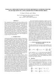
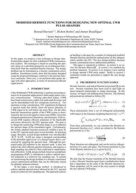
UWB EIRP Emission Level (dBm/MHz)<br />
0<br />
−10<br />
−20<br />
−30<br />
−40<br />
−50<br />
System 2<br />
System 1<br />
FCC Mask<br />
−60<br />
0 2 4 6 8 10 12 14 16 18 20<br />
Frequency (GHZ)<br />
Figure 1: The power spectral density of the Gaussian monocycle<br />
<strong>pulse</strong> <strong>for</strong> the tow peak amplitude A 1<br />
and A 2<br />
and the<br />
FFC indoor spectral emission mask<br />
3. PROBLEM STATEMENT<br />
Based on the FCC spectral mask S´ f µ illustrated in figure.1,<br />
we observe that most of the UWB signal power should be allocated<br />
to the 3.1 - 10.6GHz band, while considerable attenuation<br />
is imposed in other regions of the spectrum, especially<br />
<strong>for</strong> frequencies up to 3.1GHz. These constraints are designed<br />
to avoid interference to legacy narrowband systems. Accordingly,<br />
we define F p : f Ò f ¾ 31106℄GHz as the UWB<br />
passband 4℄. Be<strong>for</strong>e introducing the problem statement, let<br />
us first consider the Gaussian monocycle <strong>pulse</strong>, which has<br />
been widely adopted by UWB radar and communication systems.<br />
The Gaussian monocycle can be expressed as<br />
g´tµ 2 Ô eA t<br />
τ g<br />
e 2´ t<br />
τ g<br />
µ 2 (6)<br />
where τ g is the time duration between its minimum and maximum<br />
values and A represents its peak amplitude. The <strong>pulse</strong><br />
duration is approximately equal to T g 4τ g Accordingly,<br />
the Fourier Trans<strong>for</strong>m (FT) of g´tµ is<br />
G´ f µ 1 2<br />
Ö<br />
2e<br />
π<br />
A<br />
fg<br />
2 e 1 2<br />
f 2<br />
fg<br />
(7)<br />
where f g : 1´πτ g µ is the frequency where G´ f µ is<br />
maximum11℄.<br />
In figure.1, we have plotted the FFC indoor spectral emission<br />
mask and frequency response G´ f µ <strong>for</strong> the two amplitudes<br />
A 1<br />
(system 1) and A 2<br />
(system 2). Trying to maximize<br />
transmission power, system 1 violates the FFC spectrum<br />
mask; whereas trying to respect the FFC mask, system 2 does<br />
not exploit the FFC mask in a power efficient manner. Consequently,<br />
the Gaussian monocycle does not lead to <strong>optimal</strong><br />
utilization of the spectrum assigned by FFC.To maximize the<br />
received SNR, the spectral shape of UWB <strong>pulse</strong> p´tµ should<br />
<strong>optimal</strong>ly utilize the allowed bandwidth and power spectra,<br />
while at the same time respecting the spectral mask S´ f µ<br />
The spectrum utilization efficiency can be measured by the<br />
normalized effective signal power (NESP) ψ4℄ :<br />
ψ <br />
ÊF p<br />
P´ f µ 2<br />
where P´ f µ is the FT of p´tµ<br />
¢ 100 (8)<br />
2 ÊF S´ p<br />
f µ<br />
The objective of our <strong>pulse</strong> design problem is to find p´tµ<br />
that maximizes ψ under the spectral mask constraint. this<br />
can be mathematically <strong>for</strong>mulated as follows:<br />
maxψ subject to P´ f µ S´ f µ f (9)<br />
p´tµ<br />
4. NEW DESIGN APPROACH<br />
In this section, we exploit the property of Hermite function<br />
to design time-limited <strong>pulse</strong> shape <strong>for</strong> UWB systems , with<br />
given frequency magnitude characteristic. To control <strong>pulse</strong><br />
width of the Hermite <strong>functions</strong>, we propose to use a scaling<br />
factor α, <strong>for</strong> each Hermite function d n´tµ (Iftheα increases,<br />
the bandwidth of the <strong>pulse</strong> becomes narrower). Consequently,<br />
the bandwidth can be fitted into the bounds of the<br />
spectral mask.<br />
From the <strong>modified</strong> Hermite function, we construct a set<br />
of even <strong>functions</strong> defined by:<br />
g iα ´tµ ´ di´αtµ ¢ cos´2πtf c µ if i is even<br />
d i´αtµ ¢ sin´2πtf c µ if i is odd<br />
(10)<br />
where f c is the center frequency of the FFC mask.<br />
It is worth noting, that these g iα ´tµ <strong>for</strong>ms a set of orthogonal<br />
function.<br />
The Fourier trans<strong>for</strong>mation G iα ´ f µ FT´g iα ´tµµ is<br />
given by:<br />
if i 2n<br />
<br />
´ 1µ nÔ <br />
2π<br />
2α<br />
d i 2π´ f<br />
α<br />
f c µ · d i 2π´ f<br />
α · f cµ<br />
G iα ´ f µ if i 2n · 1<br />
<br />
Ô <br />
2π´ 1µ<br />
n·1<br />
2α<br />
d i 2π´ f<br />
α<br />
f c µ d i 2π´ f<br />
α · f cµ<br />
(11)<br />
For an appropriate α, the two terms d i 2π´ f<br />
α<br />
f c µ and<br />
<br />
d i 2π´ f<br />
α · f cµ will not interfere, so we can approximate<br />
´ f µ <strong>for</strong> f ¾ 0 ·∞ as follows:<br />
G iα<br />
G iα ´ f µ <br />
<br />
´ 1µ nÔ <br />
2π<br />
2α<br />
d i 2π´ f<br />
α<br />
f c µ if i 2n<br />
Ô 2π´ 1µ<br />
n·1<br />
2α<br />
<br />
d i 2π´ f<br />
α<br />
f c µ if i 2n · 1<br />
For a fixed scaling factor αwe build a sub-field E<br />
Ò<br />
Lα Ó<br />
spanned by L orthogonal <strong>functions</strong> g g 0α 1α ¡¡¡ g L 1α<br />
.<br />
We restrict, the optimization problem, by finding an <strong>optimal</strong><br />
<strong>pulse</strong> p Lα ´tµ in the sub-field E Lα . Thus p Lα ´tµ will be expressed<br />
as follows:<br />
∑<br />
p Lα ´tµ L 1<br />
i0<br />
x i g iα<br />
´tµ (12)<br />
¬<br />
¬ ¬¬<br />
The power spectrum S p´ f µ := ¬P Lα´ f 2 µ of pLα<br />
.<br />
´tµ is<br />
.
given by<br />
S p´ f µ<br />
¬<br />
L 1<br />
∑<br />
i0<br />
x i<br />
G iα ´ f µ ¬ ¬¬¬¬<br />
2<br />
(13)<br />
<br />
<br />
L 1<br />
100<br />
90<br />
80<br />
2<br />
∑ x i<br />
G iα ´ f µ <br />
i0<br />
For the chosen <strong>pulse</strong> model 12 and an appropriate α, the<br />
NESP can be approximated as follows:<br />
ψ<br />
70<br />
60<br />
50<br />
<br />
L 1 ÊF ´ p<br />
∑<br />
i0<br />
ψ <br />
<br />
x i<br />
G iα ´ f µµ 2<br />
df<br />
ÊF p<br />
S´ f µ df<br />
<br />
<br />
Ê L 1<br />
2<br />
·∞<br />
0 ´ ∑ x i<br />
G iα ´ f µµ df<br />
i0<br />
Ê ·∞<br />
0 S´ f µ df<br />
¢ 100 (14)<br />
¢ 100<br />
Using the orthogonality property of function g iα ´tµ, the<br />
NESP can be approximated by:<br />
L 1<br />
1<br />
2α ∑ x 2 i<br />
i0<br />
ψ Ê ·∞<br />
0 S´ f µ df ¢ 100<br />
Due to the fact that G iα ´ f µ is real, the Fourier trans<strong>for</strong>mation<br />
P Lα ´ f µ of our designed <strong>pulse</strong> p Lα ´tµ will be also<br />
¬<br />
¬ ¬¬<br />
real, so the mask constraint ¬P Lα´ f 2 µ S´ f µ can also be<br />
equivalently written as:<br />
Ô<br />
S´ f µ PLα ´ f Ô µ S´ f µ (15)<br />
In the frequency domain, the mask was represented with<br />
infinite number of linear constraints. We relax this constraint<br />
by a discretization method, in witch the entire UWB passband<br />
is sampled in an ascending order at a fine frequency resolution<br />
to <strong>for</strong>m a frequency set f 0<br />
f 1<br />
¡¡¡ f M 1 Now our<br />
<strong>pulse</strong> design problem defined over the continuous frequency<br />
variable f can then be re<strong>for</strong>mulated as a convex quadratic<br />
function of X x 0<br />
x 1<br />
¡¡¡ x L 1 ℄T with finite number of linear<br />
constraints <strong>for</strong>mulated as follows:<br />
min<br />
x<br />
<br />
<br />
100<br />
2α Ê ·∞<br />
0 S´ f µ df<br />
HLα<br />
H Lα<br />
¾<br />
<br />
X <br />
<br />
<br />
L 1<br />
∑ x 2 i (16)<br />
i0<br />
¿<br />
S´ f 0<br />
µ<br />
S´ f 1 µ<br />
.<br />
S´ f M 1 µ<br />
<br />
<br />
where H Lα is the matrix defined as follows:<br />
H Lα<br />
<br />
¼<br />
<br />
<br />
G f 0α 0<br />
G f 0α 1<br />
.<br />
¡<br />
¡<br />
G 0α f M 1<br />
¡<br />
. ¡¡¡<br />
¡¡¡ G L 1α f 0<br />
¡¡¡ G f L 1α 1<br />
.<br />
¡<br />
¡<br />
¡¡¡ G L 1α f M 1<br />
¡<br />
40<br />
30<br />
½<br />
<br />
3<br />
Our<br />
following<br />
4<br />
global<br />
optimization<br />
5<br />
design<br />
5.<br />
6<br />
min<br />
α<br />
st<br />
DESIGN<br />
7<br />
problem<br />
problem:<br />
min<br />
X<br />
HLα<br />
8<br />
α<br />
ψ´Xαµ<br />
Lα<br />
EXAMPLES<br />
9<br />
now<br />
<br />
10<br />
be<br />
11<br />
written<br />
12<br />
as<br />
13<br />
x10 9<br />
can<br />
<br />
<br />
<br />
X M<br />
H<br />
Figure 2: Evolution of the normalized effective signal power<br />
versus the scaling factors α, <strong>for</strong> L 10 and N 21.<br />
the<br />
(17a)<br />
To relax the optimization problem 17, we split it into tow<br />
steps. First, <strong>for</strong> a fixed α, we solve the convex problem described<br />
by equation 16, and compute the optimum NESP denoted<br />
ψ L´αµ, In the second step, we analyze the evolution<br />
of ψ L´αµ Versus α. Then we choose the optimum α, α opt ,<br />
which maximizes ψ L´αµ.<br />
In this section, we apply our approach design method, presented<br />
in the previous section, to design <strong>optimal</strong> ultrawadeband<br />
<strong>pulse</strong> shaper. To lessen the hardware implementation<br />
difficulty, we set the sampling frequency to be relatively<br />
low value of 25GHz.<br />
We denote N the number of taps <strong>for</strong> the <strong>pulse</strong> p Lα ´tµ.<br />
So,N will fix the <strong>pulse</strong> duration.<br />
In the first case, we solve the optimization problem <strong>for</strong><br />
L 10, and N 21, using the optimization package of Matlab.<br />
In figure 2, we report the evolution of ψ 10´αµ versus α.<br />
We deduce that the optimum α is equal to α opt 932 10 9 .<br />
The <strong>optimal</strong> generated <strong>pulse</strong> and its spectrum is presented in<br />
figure 3.Compliant to the FFC mask, the synthesized <strong>pulse</strong><br />
achieves a maximum NESP of ψ 807%<br />
In a second case, we have find that <strong>for</strong> N 11 the <strong>optimal</strong><br />
factor α opt is equal to 1226 10 9 , where the synthesized<br />
<strong>pulse</strong> achieves a maximum NESP of ψ 687%. The <strong>optimal</strong><br />
generated <strong>pulse</strong> and its FT are plotted in figure 4.<br />
In figure 5 we have compared the evolution of the <strong>optimal</strong><br />
normalized effective signal power achieved by the <strong>pulse</strong><br />
shapers designed in 4℄ with our <strong>new</strong> design <strong>pulse</strong> shaper versus<br />
the <strong>pulse</strong> duration. It is clear that our design utilizes the<br />
FFC spectral mask most efficiently. As example, <strong>for</strong> N 10,<br />
the <strong>pulse</strong> in 4℄ has ψ 43% however our <strong>new</strong> <strong>pulse</strong> has<br />
ψ 687%
Spectrum (dB)<br />
10<br />
0<br />
−10<br />
−20<br />
−30<br />
−40<br />
Synthesized <strong>pulse</strong> N=21<br />
FCC spectral Mask S(f)<br />
−50<br />
0 5 10<br />
f (GHZ)<br />
Amplitude<br />
0.6<br />
0.5<br />
0.4<br />
0.3<br />
0.2<br />
0.1<br />
0<br />
−0.1<br />
−0.2<br />
−0.3<br />
−0.4<br />
−0.4 −0.2 0 0.2 0.4<br />
Time (ns)<br />
Figure 3: For N 21, <strong>optimal</strong>ly designed <strong>pulse</strong> shaper and<br />
its FT <strong>for</strong> α 932 10 9 and L 10<br />
Spectrum (dB)<br />
10<br />
0<br />
−10<br />
−20<br />
−30<br />
−40<br />
Synthesized <strong>pulse</strong> N=11<br />
FCC spectral Mask S(f)<br />
−50<br />
0 5 10<br />
f (GHZ)<br />
Amplitude<br />
0.5<br />
0.4<br />
0.3<br />
0.2<br />
0.1<br />
0<br />
−0.1<br />
−0.2<br />
−0.3<br />
−0.2 −0.1 0 0.1 0.2<br />
Time (ns)<br />
Figure 4: For N 11, <strong>optimal</strong>ly designed <strong>pulse</strong> shaper and<br />
its FT <strong>for</strong> α 1226 10 9 and L 10<br />
%<br />
100<br />
90<br />
80<br />
70<br />
60<br />
50<br />
Maximum achievable ψ of N fom [7]<br />
Maximum achievable ψ of N based on the <strong>new</strong> design method<br />
40<br />
10 15 20 25<br />
N<br />
Figure 5: Evolution of the maximum normalized effective<br />
signal power versus the <strong>pulse</strong> duration.<br />
6. CONCLUSION<br />
In this paper, we have proposed a <strong>new</strong> <strong>pulse</strong> design approach.<br />
The approach consists on searching the <strong>optimal</strong> <strong>pulse</strong> in a<br />
sub-field spanned by a set of orthogonal <strong>functions</strong>, built from<br />
the <strong>modified</strong> Hermite <strong>functions</strong>. The problem becomes a<br />
linearly constrained convex problem. The obtained results,<br />
show that the generated <strong>pulse</strong>s meet the FCC mask and out<br />
per<strong>for</strong>m other design approach.<br />
REFERENCES<br />
[1] M. Z. Win and R. A. Scholtz, “Im<strong>pulse</strong> radio: How it<br />
works”, IEEE Commun. Lett., vol. 2, pp. 3638, Febuary<br />
1998.<br />
[2] H.Sheng, P.Orlik, “On the Spectral and Power Requirements<br />
<strong>for</strong> Ultra-Wideband Transmission”, Communications,<br />
2003, ICC03, IEEE International Comm. Conference,Volume:1,2003<br />
pp:738-742<br />
[3] Parr, B.; ByungLok Cho; Wallace, K.; Zhi Ding, “A<br />
novel ultra-wideband <strong>pulse</strong> design algorithm”, Communications<br />
Letters , IEEE, vol. 7, no. 5, pp. 219-221,<br />
May 2003.<br />
[4] X. Wu, Z. Tian, T. N. Davidson, G. B. Giannakis, “Optimal<br />
Wave<strong>for</strong>m Design <strong>for</strong> UWB Radios”, Proceedings<br />
of IEEE International Conference on Acoustics,<br />
Speech and Signal Processing (ICASSP’2004), Montreal,<br />
QC, vol. 4, pp. 521-524, May 17-21, 2004.<br />
[5] N.C. Beaulieu and B. Hu, “A Novel Pulse Design Algorithm<br />
<strong>for</strong> Ultra-wideband Communications”, IEEE<br />
GLOBECOM, Dallas, Texas, Nov. 29-Dec. 3, 2004.<br />
[6] X. Wu, Z. Tian, T. N. Davidson, G. B. Giannakis, “Orthogonal<br />
Wave<strong>for</strong>m Design <strong>for</strong> UWB Radios”, Proceedings<br />
of IEEE Signal Processing Workshop on Advances<br />
in Wireless Communications (SPAWC2004),<br />
Lisbon, July 11-14, 2004.<br />
[7] Zeng, D., A. Annamalai Jr., A.I. Zaghloul,“ Pulse Shaping<br />
Filter Design in UWB System”, IEEE Conference<br />
on Ultra Wideband Systems and Technologies, pp.<br />
6670, November 2003.<br />
[8] M. Ouertani, H. Besbes, A. Bouallegue, “A <strong>new</strong> design<br />
approach <strong>for</strong> ODMA systems”, 2004 First International<br />
Symposium on Control, Communications and<br />
Signal Processing, ISCCSP 2004, Tunisia 2004.<br />
[9] G. Andrews, R. Askey, R. Roy, Special <strong>functions</strong>,<br />
edited by Cambridge University Press, Cambridge, UK,<br />
1999.<br />
[10] Ghavami M., L. B. Michael and R. Kohno, “Hermite<br />
Function Based Orthogonal Pulses <strong>for</strong> Ultra Wideband<br />
Communication”, in Proc. International Symposium<br />
on Wireless Personal Multimedia Communications<br />
(WPMC), Aalborg, Denmark, pp. 437440, Sep.<br />
2001.<br />
[11] X. Luo, L. Yang, and G. B. Giannakis, “Designing Optimal<br />
Pulse-Shapers <strong>for</strong> Ultra-Wideband Radios,” IEEE<br />
Journal on Communications and Networks, vol. 5, no.<br />
4, pp. 344-353, December 2003.