Bulletin 122 Modul-r - Tinius Olsen
Bulletin 122 Modul-r - Tinius Olsen
Bulletin 122 Modul-r - Tinius Olsen

Create successful ePaper yourself
Turn your PDF publications into a flip-book with our unique Google optimized e-Paper software.
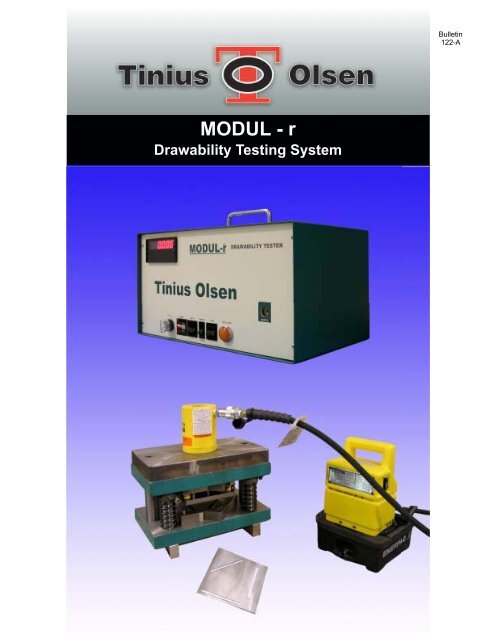
MODUL - r<br />
Drawability Testing System<br />
<strong>Bulletin</strong><br />
<strong>122</strong>-A
The <strong>Modul</strong>-r is the most efficient and<br />
economical ‘Go/No-Go’ testing method<br />
available for determining if given batch of<br />
sheet steel is suitable for a deep-drawing<br />
application<br />
If you can’t assess the drawability of your<br />
sheet steel, you can’t be certain that your<br />
steel will perform properly when deep-drawn<br />
in a particular application. Without the proper<br />
drawability characteristics, it could fracture in<br />
the die or create excessive “ears” that could<br />
ruin an entire production run. At the same<br />
time, you can’t afford to hold up production<br />
while obtaining that quality control<br />
assurance…..conventional testing takes<br />
time.<br />
The <strong>Modul</strong>-r testing system helps cut<br />
potential material and production losses<br />
because you can accurately assess the<br />
drawability and earing characteristics of any<br />
carbon or other magnetic sheet steel in 5<br />
minutes or less….compared to the three,<br />
plus, hours conventional testing methods<br />
can take. Additionally, the <strong>Modul</strong>-r can be<br />
used by personnel with little or no technical<br />
background.<br />
The <strong>Modul</strong>-r is compact and light enough to<br />
make it truly transportable anywhere in the<br />
plant and only requires a tabletop as a test<br />
surface. The unit isn’t susceptible to the<br />
normal floor vibrations of stamping or steelproducing<br />
environments so can be kept<br />
close to the pressing operations, eliminating<br />
the downtime normally associated with<br />
coordinating testing operations between<br />
plant locations. Any production variable<br />
changes can be handled with a minimum of<br />
downtime and material loss.<br />
Operation is extremely simple. First, the<br />
operator prepares three test strips from a<br />
sample sheet about150 mm square; after<br />
marking the rolling direction of the sheet,<br />
three narrow test strips are blanked, or<br />
sheared, at 0 o , 45 o and 90 o to this direction.<br />
For optimum ease, all three test strips can<br />
be produced simultaneously with the punch<br />
press described later.<br />
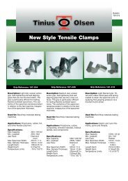
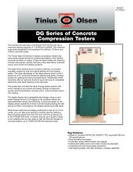
Fig 1. How the <strong>Modul</strong> r stacks up<br />
<strong>Modul</strong> r<br />
Punch Press<br />
Testing involves simply inserting a steel strip<br />
into the test slot and depressing the ‘TEST’<br />
button for a few seconds while the resonant<br />
frequency appears on the display. The<br />
operator records the reading on a worksheet<br />
and repeats the test for the remaining two<br />
strips.<br />
The relationship between r and Young’s<br />
modulus allows us to readily determine the<br />
drawing and earing tendencies of the<br />
sample. Taking the resonant frequency and<br />
using the data handbook and worksheet<br />
format we provide, the operator performs a<br />
short series of indicated calculations to<br />
generate the necessary information.<br />
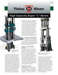
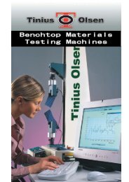
The <strong>Modul</strong>-r system punch press is<br />
recommended for punching out samples in<br />
the required configuration. This easy to use<br />
unit will simultaneously punch out all three<br />
required samples in one smooth stroke and<br />
consists of an electric pump, piston and<br />
cylinder, and all necessary dies.<br />
Preparing samples is easy too. Mark the<br />
rolling direction along the center line of a<br />
2<br />
150 mm sample from the sheet and insert<br />
the sample in the press. The piston lowers<br />
and punches out three clean test strips from<br />
the sample: one parallel to the rolling<br />
direction (0 o ), one 45 o to the rolling direction,<br />
and one at 90 o to the rolling direction.<br />
Two sizes of punch press are available, as<br />
are two models of <strong>Modul</strong> r – see attached<br />
chart for sample thickness limitations for<br />
each system.<br />
<strong>Modul</strong> r I (0.008" to 0.080" thick material)<br />
<strong>Modul</strong> r II (0.02 to 0.125" thick material)<br />
Punch press 1 (thicknesses up to 0.04")<br />
Punch press II (0.0358" to 0.125" thick material)<br />
Many years ago, engineers at US Steel’s<br />
Monroeville Research Center studied the<br />
correlation between the average plastic<br />
strain ratio, and the average Young’s<br />
<strong>Modul</strong>us of a sample of steel. They observed<br />
that the higher the plastic strain ratio (r or r m)<br />
of a steel, the higher the drawability. They<br />
also discovered that Young’s moduli could<br />
easily be determined by using a resonant<br />
frequency technique, which led to their<br />
development of the <strong>Modul</strong>-r now produced<br />
by <strong>Tinius</strong> <strong>Olsen</strong>.<br />
For most commercially produced low carbon<br />
steel sheets, the plastic strain ratio ® varies<br />
with the test direction relative to the rolling<br />
direction. This variation is called the planar<br />
anisotropy, which correlates with the<br />
tendency of the sheet to form “ears” upon<br />
drawing.<br />
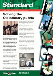
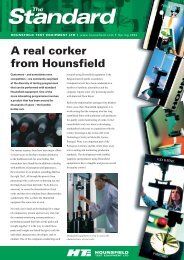
The <strong>Modul</strong>-r employs a simple feedback<br />
system (called a magnetostrictive oscillator)<br />
consisting of a measuring head, an amplifier<br />
and an electronic counter. The measuring<br />
head consists of three coils that form the<br />
sample chamber. When the sample is<br />
inserted and the TEST button depressed, an<br />
alternating field is created by the current<br />
passing through the coil network, producing<br />
cyclical longitudinal expansion and<br />
contraction in the sample through a process<br />
called magnetostriction.<br />
These vibrations match the characteristic<br />
velocity of sound for that particular sample,<br />
or resonant frequency. This frequency Is<br />
displayed within seconds and is also used to<br />
control the oscillator circuit, stabilizing the<br />
output to a high degree of accuracy.<br />
Drive<br />
Coil<br />
Bias<br />
Coil<br />
Pickup<br />
Coil<br />
Specifications subject to change without notice<br />
Contact Your Local Representative:<br />
1065 Easton Road, Horsham, PA 19044 USA<br />
(215) 675-7100 Fax (215) 441-0899<br />
www.<strong>Tinius</strong><strong>Olsen</strong>.com<br />
6 Perrywood Business Park, Honeycrock Lane,<br />
Salfords, Redhill, Surrey RH1 5DZ England<br />
+44 (0) 1737 765001 Fax +44 (0) 1737 764768<br />
Counter<br />
Steel specimen<br />
Special<br />
Amplifier