Using Selective Withdrawal to Coat Microparticles - Itai Cohen Group
Using Selective Withdrawal to Coat Microparticles - Itai Cohen Group
Using Selective Withdrawal to Coat Microparticles - Itai Cohen Group

You also want an ePaper? Increase the reach of your titles
YUMPU automatically turns print PDFs into web optimized ePapers that Google loves.
R EPORTS<br />
<strong>Using</strong> <strong>Selective</strong> <strong>Withdrawal</strong> <strong>to</strong><br />
<strong>Coat</strong> <strong>Microparticles</strong><br />
<strong>Itai</strong> <strong>Cohen</strong>, 1 Hui Li, 2 James L. Hougland, 2 Milan Mrksich, 2<br />
Sidney R. Nagel 1<br />
We report a method that uses the process of selective withdrawal of one fluid<br />
through a second immiscible fluid <strong>to</strong> coat small particles with polymer films.<br />
Fluid is withdrawn through a tube with its orifice slightly above a water-oil<br />
interface. Upon increasing the flow rate, there is a transition from a state where<br />
only oil is withdrawn <strong>to</strong> a state where the water, containing the particles <strong>to</strong> be<br />
coated and appropriate prepolymer reagents, is entrained in a thin spout along<br />
with the oil. The entrained particles eventually cause the spout interface <strong>to</strong><br />
break, producing a thin coat of controllable thickness around each particle,<br />
which can be subsequently polymerized using chemical reagents, light, or heat.<br />
This method allows flexibility in the chemical composition and thickness of the<br />
conformal coatings.<br />
<strong>Coat</strong>ed microparticles are important in a<br />
range of technologies, including solid-phase<br />
resins for the synthesis of combina<strong>to</strong>rial libraries<br />
(1), immobilized catalysts in chemical<br />
production (2), protective coatings for cell<br />
and tissue encapsulation (3, 4), and vehicles<br />
1<br />
James Frank Institute and Department of Physics,<br />
2<br />
Department of Chemistry, University of Chicago,<br />
Chicago, IL 60637, USA.<br />
for local drug delivery (5). Several coating<br />
methods are used because no single technique<br />
is best suited for all types of particles and<br />
polymerization schemes. Current options for<br />
encapsulation include droplet generation (6)<br />
or coacervation (7), emulsion formation (8),<br />
polyelectrolyte multilayering (9), and direct<br />
polymerization from a surface-adsorbed initia<strong>to</strong>r<br />
(10). Many of these techniques (6–8)<br />
have the limitation that they produce particles<br />
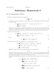
Fig. 1. (A) Diagram of the apparatus used in selective withdrawal. The tube orifice is a distance S<br />
from the unperturbed interface, and the rate of <strong>to</strong>tal fluid withdrawal is Q. A gear pump (Tuthill<br />
D9005M) was used <strong>to</strong> withdraw the fluids through a tube with S between 6.5 and 8.0 mm. Q was<br />
typically between 0.7 and 1.5 ml/s. Siphoning can also be used. (B) Pho<strong>to</strong>graph of a water spout<br />
entrained with the heavy mineral oil in a tube with orifice diameter 1.6 mm. The viscosities of the<br />
water and oil are 1.0 cSt and 195 cSt, respectively, at room temperature. The surface tension of the<br />
water-oil interface is 35 3 dynes/cm.<br />
of a constant <strong>to</strong>tal size, including the coat,<br />
even when the uncoated particles have a heterogeneous<br />
size distribution. Other coating<br />
techniques (9, 10) are able <strong>to</strong> produce coats of<br />
uniform thickness, but may often be restricted<br />
with respect <strong>to</strong> the chemical composition<br />
of the coat and the polymerization schemes<br />
that can be used. There remains an important<br />
need for a versatile coating technology that<br />
allows for the use of a variety of polymerization<br />
schemes and can apply uniform coats of<br />
diverse composition and controllable thickness<br />
on<strong>to</strong> polydisperse particles.<br />
We report a method that uses the process of<br />
selective withdrawal (11, 12) <strong>to</strong> apply polymer<br />
coats of uniform thickness and varying composition<br />
on<strong>to</strong> polydisperse particles. In the simplest<br />
version of this experiment, a tube is introduced<br />
in<strong>to</strong> a container such that its tip is suspended<br />
at a height S above an interface separating<br />
two immiscible liquids (Fig. 1A). For<br />
low rates of fluid withdrawal Q, only the upper<br />
fluid, which in this experiment is oil, is withdrawn<br />
through the tube. An increase in Q (or a<br />
decrease in S) leads <strong>to</strong> a transition where the<br />
lower liquid (which in this experiment is water)<br />
is entrained in a thin spout along with the oil<br />
(Fig. 1B) (12). Once the spout has formed, an<br />
increase in Q or a reduction in S causes the<br />
spout <strong>to</strong> thicken. A higher oil viscosity produces<br />
thinner initial spouts (13).<br />
When particles are added <strong>to</strong> the aqueous<br />
phase, they become entrained in the spout.<br />
Because the spout gets progressively thinner<br />
as it rises above the interface, it eventually<br />
becomes thinner than the entrained particle,<br />
which causes the interface <strong>to</strong> stretch (Fig. 2)<br />
and eventually break both above and below<br />
the particle, leaving a thin water shell surrounding<br />
the particle. A key feature of the<br />
spout collapse is that larger particles break up<br />
the spout earlier than smaller ones, and so the<br />
thickness of the shell is relatively independent<br />
of the particle size. The viscous outer<br />
fluid (14) suppresses flow instabilities in the<br />
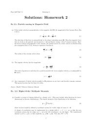
Fig. 2. Pho<strong>to</strong>graph of a poppy seed inside<br />
the water spout. The spout stretches<br />
around the particle and eventually<br />
breaks up both above and below the<br />
particle <strong>to</strong> produce particles encapsulated<br />
in an aqueous shell of uniform<br />
thickness. The orifice diameter is 1.2<br />
mm and the particle diameter is about<br />
0.8 mm.<br />
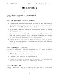
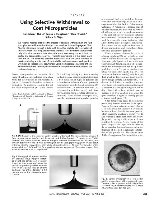
Fig. 3. Optical micrograph of a corn pollen<br />
particle encapsulated with a polyamide coat.<br />
The corn pollen appears as a dark, solid elliptical<br />
object 83 m in diameter; the coat is about<br />
38 m thick. Scale bar, 100 m.<br />
www.sciencemag.org SCIENCE VOL 292 13 APRIL 2001 265
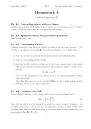
Fig. 4. Plot of coat thickness versus<br />
particle diameter. The flat<br />
distribution indicates that coat<br />
thickness does not change with<br />
particle size. The inset shows a<br />
his<strong>to</strong>gram distribution of coat<br />
thickness for the same run in<br />
which both Q and S are held<br />
constant at 1.5 ml/s and 8.0 mm,<br />
respectively. The distribution can<br />
be fit with a Gaussian and has a<br />
standard deviation of 4 m.<br />
spout and aids particle collection. This process<br />
can be adopted <strong>to</strong> apply polymer coatings<br />
on<strong>to</strong> the particles by adding reagents <strong>to</strong><br />
the water that can subsequently be crosslinked<br />
(15). As with capillary flow focusing<br />
(16), selective withdrawal prevents tip clogging<br />
(17) by never allowing the prepolymer<br />
spout <strong>to</strong> <strong>to</strong>uch the tube.<br />
We now describe one example of applying<br />
a polyamide coat by chemically crosslinking<br />
a low molecular weight poly(ethylene<br />
glycol). The lower phase consists of D 2<br />
O<br />
containing O,O-bis(2-aminopropyl) poly-<br />
(ethylene glycol), molecular weight 800 [5%<br />
w/v, viscosity 1.4 cSt (where 1 cSt 10 2<br />
cm 2 s 1 at room temperature)] and a polydisperse<br />
suspension of corn pollen particles<br />
(average diameter 100 m). The higher density<br />
of D 2<br />
O relative <strong>to</strong> H 2<br />
O keeps the corn<br />
pollen particles near the interface, where they<br />
efficiently enter the spout. The encapsulated<br />
particles are then deposited in a separate bath<br />
of heavy mineral oil containing 1,3,5-benzenetricarbonyl<br />
trichloride (15 mM). Upon contact<br />
with the aqueous film, the reagent reacts<br />
with the amino groups of the polyethylene<br />
glycol <strong>to</strong> produce a cross-linked coat around<br />
the particle (Fig. 3). With this scheme, the<br />
particle is never exposed <strong>to</strong> the reagent that<br />
induces polymerization. As described below,<br />
the coat can be made much thinner or thicker<br />
R EPORTS<br />
than that shown in Fig. 3.<br />
We used confocal and optical microscopies<br />
<strong>to</strong> determine the thickness and uniformity of the<br />
polymer coats. The inset of Fig. 4 shows a<br />
representative distribution of coat thickness corresponding<br />
<strong>to</strong> a run with both flow rate Q and<br />
tube height S held constant. Figure 5 shows the<br />
mean coat thickness as a function of Q for S <br />
6.5 mm. For flow rates of 0.74 ml/s, the corn<br />
pollen coats had a thickness of 15 5 m.<br />
Increasing Q produces thicker coats, consistent<br />
with the trend that the spout becomes thicker at<br />
higher Q. The error bars, corresponding <strong>to</strong> the<br />
standard deviations of the distributions, increase<br />
with Q. The width is due in part <strong>to</strong> drop<br />
coalescence and should decrease when fast<br />
cross-linking schemes are initiated immediately<br />
after coat formation. Such rapid cross-linking<br />
can also be used <strong>to</strong> counteract buoyancy effects<br />
that occasionally yield off-center particles.<br />
In contrast <strong>to</strong> the current droplet generation<br />
techniques (6–8), selective withdrawal<br />
ensures that all particles receive a coat of<br />
equal mean thickness (Fig. 4), and this thickness<br />
can be controlled by adjusting the experimental<br />
parameters (for example, by varying<br />
Q as shown in Fig. 5). This might be<br />
useful in potential future applications involving<br />
the coating of transplanted biological<br />
cells in order <strong>to</strong> protect them from the host<br />
immune system (3, 4). For example, the irregular<br />
shape and size of cell clusters (such as<br />
islet cells transplanted <strong>to</strong> regulate the delivery<br />
of insulin in<strong>to</strong> the bloodstream) makes it<br />
difficult <strong>to</strong> produce coats that are uniform in<br />
thickness.<br />
We have described one possible scheme<br />
that uses selective withdrawal <strong>to</strong> encapsulate<br />
a particle and a chemical initia<strong>to</strong>r <strong>to</strong> subse-<br />
Fig. 5. Plot of mean coat thickness as a function<br />
of Q, for S 6.5 mm. The mean thickness<br />
increases linearly with Q; error bars represent<br />
standard deviation of thickness.<br />
Fig. 6. Confocal images of a polystyrene bead coated with agarose (type XII, Sigma). After selective<br />
withdrawal, the coat was hardened by cooling the coat-plus-particle systems <strong>to</strong> temperatures<br />
lower than the gelling point of the agarose. The agarose contains PolyFluor 512 (Polysciences),<br />
which fluoresces while the polystyrene bead, 220 m in diameter, does not fluoresce. Successive<br />
cross-sectional image planes show that the agarose coat has a uniform thickness of 12 m. The<br />
agarose rings increase in diameter with cross sections nearing the particle’s equa<strong>to</strong>rial plane.<br />
Beyond this point, the particle itself starts <strong>to</strong> block the light. Scale bar, 0.4 mm.<br />
266<br />
13 APRIL 2001 VOL 292 SCIENCE www.sciencemag.org
R EPORTS<br />
Fig. 7. Optical micrograph of a poppy seed<br />
encapsulated in a poly(styrenesulfonic acid)<br />
coat. The poppy seed appears as a dark solid<br />
object 0.9 mm in diameter; the coat is 0.2 mm<br />
thick. The prepolymer used is styrene sulfonic<br />
acid sodium salt (30% w/v in D 2<br />
O) and triethylene<br />
glycol diacrylate (5% w/v in D 2<br />
O) mixed<br />
with eosin Y (0.5 mM) and triethanolamine<br />
(100 mM) as the pho<strong>to</strong>sensitizer–electron donor<br />
initiating system (18). After the selective<br />
withdrawal process, the coated particles were<br />
collected in a plastic container and irradiated<br />
for 20 min with a halogen lamp. Scale bar, 0.5<br />
mm.<br />
quently harden the coat. However, this coating<br />
method is easily generalized <strong>to</strong> allow for<br />
different ways of hardening the particle coats.<br />
With the use of appropriate reagents, this<br />
technique is also compatible with schemes<br />
that thermally or optically initiate the hardening<br />
of the coats. Figure 6 shows confocal<br />
images of a polystyrene bead encapsulated<br />
with an agarose coat that was hardened by<br />
lowering its temperature. In Fig. 7, we show<br />
an optical micrograph of a poppy seed encapsulated<br />
in a poly(styrenesulfonic acid) coat<br />
that was pho<strong>to</strong>polymerized. The selective<br />
withdrawal geometry may also be inverted by<br />
inserting the straw through the bot<strong>to</strong>m of the<br />
withdrawal container, with the straw tip positioned<br />
below the interface. Now the denser<br />
aqueous fluid is the primary fluid being withdrawn,<br />
and the particles <strong>to</strong> be coated are<br />
placed in the oil (upper fluid). This inversion<br />
extends the applicability of this coating technique<br />
<strong>to</strong> hydrophobic particles in oil-soluble<br />
reagents as well as <strong>to</strong> heavy particles in the<br />
upper fluid that will sediment <strong>to</strong> the interfacial<br />
boundary.<br />
The selective withdrawal coating technique<br />
complements other currently available<br />
techniques, such as surface-induced polymerization<br />
(10), which can also produce coats of<br />
uniform thickness on irregularly shaped particles<br />
but which often require modification of<br />
the particle surface and therefore may not be<br />
feasible. In our technique, as illustrated in the<br />
description of the polyamide coating, the particles<br />
can be completely separated from the<br />
caustic reagents that initiate the polymerization<br />
at the outer interface. Moreover, surfaceinduced<br />
polymerization requires the reagent<br />
<strong>to</strong> be stable in the solution being polymerized.<br />
This is not always possible (as with the<br />
polyamide coat installation, the trichloride<br />
reagent is unstable in aqueous solutions), and<br />
selective withdrawal can solve this problem<br />
by initiating polymerization with a reagent<br />
that is stable in the fluid surrounding the coat.<br />
Finally, many polymer coatings are either<br />
difficult [e.g., the pho<strong>to</strong>polymerized poly-<br />
(styrenesulfonic acid) coat shown in Fig. 7]<br />
or impossible (e.g., the thermally hardened<br />
agarose coat shown in Fig. 6) <strong>to</strong> prepare using<br />
techniques such as surface-induced polymerization<br />
and must be hardened in bulk. For<br />
these cases in particular, selective withdrawal<br />
presents a valuable advantage over currently<br />
available coating techniques.<br />
The selective withdrawal technique can be<br />
readily optimized. With a single tube we<br />
estimate that 10,000 particles can be coated<br />
per hour. Preliminary experiments have<br />
demonstrated that this technique can be<br />
scaled up by using an array of tubes in<br />
parallel. Injecting particles directly in<strong>to</strong> the<br />
region below the spout can make the method<br />
suitable for particles with higher density<br />
than the prepolymer. As described above,<br />
inversion of the selective withdrawal geometry<br />
can extend the applicability of this<br />
technique <strong>to</strong> hydrophobic particles in oilsoluble<br />
reagents. Because of its flexibility<br />
in polymerization schemes, its ability <strong>to</strong><br />
coat particles of many different types, and<br />
its ability <strong>to</strong> tune the thickness of the coats,<br />
this technique is an attractive option in a<br />
range of applications and a valuable addition<br />
<strong>to</strong> the reper<strong>to</strong>ire of currently available<br />
coating techniques.<br />
References and Notes<br />
1. A. J. Mendonca, X. Y. Xiao, Med. Res. Rev. 19, 451<br />
(1999).<br />
2. S. J. Shuttleworth, S. M. Allin, P. K. Sharma, Synthesis<br />
11, 1217 (1997).<br />
3. F. Lim, A. M. Sun, Science 210, 908 (1980).<br />
4. P. Soon-Shiong, Adv. Drug Deliv. Rev. 35, 259 (1999).<br />
5. R. Langer, Acc. Chem. Res. 33, 94 (2000).<br />
6. G. H. J. Wolters, W. M. Fritschy, D. Gerrits, R. Van<br />
Schilfgaarde, J. Appl. Biomater. 3, 281 (1992).<br />
7. T. Yoshioka, R. Hirano, T. Shioya, M. Kako, Biotechnol.<br />
Bioeng. 35, 66 (1990).<br />
8. E. Mathiowitz, Encyclopedia of Controlled Drug Delivery<br />
(Wiley, New York, 1999).<br />
9. E. Donath, G. B. Sukhorukov, F. Caruso, S. A. Davis, H.<br />
Mohwald, Angew. Chem. Int. Ed. 37, 2202 (1998).<br />
10. G. M. Cruise, O. D. Hegre, D. S. Scharp, J. A. Hubbell,<br />
Biotechnol. Bioeng. 57, 655 (1998).<br />
11. J. R. Lister, J. Fluid Mech. 198, 231 (1989).<br />
12. S. Blake and G. N. Ivey, J. Volcanol. Geotherm. Res.<br />
27, 153 (1986).<br />
13. I. <strong>Cohen</strong> and S. R. Nagel, in preparation.<br />
14. E. E. Timm, U.S. Patent 4,444,961 (1984).<br />
15. Even without the inclusion of particles, as originally<br />
shown by Savart [Annal. Chim. 53, 337 (1883)] and<br />
Rayleigh [Philos. Mag. 34, 177 (1892)], the prepolymer<br />
spout will break in<strong>to</strong> droplets that can be hardened,<br />
allowing the fabrication of monodisperse particles.<br />
16. A. M. Ganan-Calvo, Phys. Rev. Lett. 80, 285 (1997).<br />
17. P. B. Umbanhowar, V. Prasad, D. A. Weitz, Langmuir<br />
16, 347 (2000).<br />
18. O. Valges-Aguilera, C. P. Pathak, J. Shi, D. Watson,<br />
D. C. Neckers, Macromolecules 25, 541 (1992).<br />
19. We thank H. Rilo and A. Rotamel for early discussions<br />
that motivated these studies. We also thank C. Lassy<br />
and the Confocal Digital Imaging Facility at the University<br />
of Chicago. Supported by NSF grant DMR-<br />
9722646 and NSF Materials Research Science and<br />
Engineering Centers Program grant DMR-9808595.<br />
19 January 2001; accepted 7 March 2001<br />
Anthropogenic Warming of<br />
Earth’s Climate System<br />
Sydney Levitus, 1 * John I. An<strong>to</strong>nov, 1 Julian Wang, 2<br />
Thomas L. Delworth, 3 Keith W. Dixon, 3 Anthony J. Broccoli 3<br />
We compared the temporal variability of the heat content of the world ocean,<br />
of the global atmosphere, and of components of Earth’s cryosphere during the<br />
latter half of the 20th century. Each component has increased its heat content<br />
(the atmosphere and the ocean) or exhibited melting (the cryosphere). The<br />
estimated increase of observed global ocean heat content (over the depth range<br />
from 0 <strong>to</strong> 3000 meters) between the 1950s and 1990s is at least one order of<br />
magnitude larger than the increase in heat content of any other component.<br />
Simulation results using an atmosphere-ocean general circulation model that<br />
includes estimates of the radiative effects of observed temporal variations in<br />
greenhouse gases, sulfate aerosols, solar irradiance, and volcanic aerosols over<br />
the past century agree with our observation-based estimate of the increase in<br />
ocean heat content. The results we present suggest that the observed increase<br />
in ocean heat content may largely be due <strong>to</strong> the increase of anthropogenic gases<br />
in Earth’s atmosphere.<br />
Studies using instrumental data <strong>to</strong> document<br />
a warming of Earth’s climate system due <strong>to</strong><br />
increasing concentrations of greenhouse gases<br />
(GHGs) have focused on surface air temperature<br />
and sea surface temperature (1).<br />
These variables have proved invaluable for<br />
documenting an average warming of approximately<br />
0.6°C at Earth’s surface (1) during<br />
the past 100 years. Recent comparisons (2–4)<br />
with paleoclimatic proxy data indicate that<br />
www.sciencemag.org SCIENCE VOL 292 13 APRIL 2001 267