
Create successful ePaper yourself
Turn your PDF publications into a flip-book with our unique Google optimized e-Paper software.
Introduction to Rheodyne ® Manual <strong>Valves</strong><br />
HIGH PRESSURE VALVES<br />
Sample Injectors<br />
How to Choose a Sample Injector<br />
Table I below compares the characteristics of Rheodyne manual sample<br />
injectors and will help you choose the most suitable model.<br />
Types and Capabilities<br />
Models ending in 25 (i.e. 7725) are dual mode injectors. Dual mode<br />
injectors can use both the partial-filling and the complete-filling<br />
method for loading the sample loop (See the “Sample Loop Loading”<br />
Application Note on page 98). They are variable volume injectors<br />
because they allow the loading of various sample volumes. These<br />
dual mode injectors, also called front-loading injectors, have a needle<br />
port for loading sample built into the handle. The unique Rheodyne<br />
injection port design allows the tip of the needle to connect directly<br />
to the sample loop for no sample loss during loading.<br />
Models ending in 10 (i.e. 7010) are single mode injectors. Single mode<br />
injectors use only the complete-filling method to load the sample loop.<br />
They are called fixed loop injectors as the sample loop size determines<br />
the sample volume. These injectors require a Loop Filler Port accessory<br />
(page 96), as a needle port is not built into the valve handle. There is not<br />
a direct connection between the syringe and the sample loop. Therefore,<br />
an excess of sample must be used to overfill the Loop Filler Port and<br />
completely fill the sample loop.<br />
Models with an “i” suffix (i.e. 7725i) are identical to the models with the<br />
same numbers but the “i” designates a built-in position sensing switch.<br />
The switch provides the chromatograph with a reproducible start signal<br />
to mark the injection time in the data system.<br />
The reproducibility of manual sample injectors depends on operator<br />
skill, syringe calibration, and the loading method. Partial-filling method<br />
is typically reproducible to 1.0% relative standard deviation (RSD).<br />
Complete-filling method is reproducible to 0.1% RSD for loops 5 µL.<br />
Scale, Sample Volume, and Loop Size<br />
Analytical scale models are for conventional columns with samples from<br />
1.0 µL to 5.0 mL. Microscale models are for 1.0 mm and 2.0 mm inner<br />
diameter columns. Model 8125 has a sample range of 0.1 µL to 500 µL,<br />
and can be used for both analytical and micro columns. Preparative<br />
scale models are for columns with diameters from 1 to 10 cm, and<br />
operate at high flow rates with samples from 100 µL to 20 mL.<br />
Liquid Contact Materials<br />
All models have a polymeric rotor seal of Vespel ® <br />
Tefzel ® or PEEK <br />
PEEK. Most models have an inert ceramic stator face assembly.<br />
Make-Before-Break (MBB ® )<br />
Models incorporating Rheodyne’s patented MBB architecture design<br />
<br />
positions. MBB greatly reduces transient pressure shocks and is<br />
benefi cial for fl ow-sensitive detectors, fragile columns, and pumps.<br />
Models 7725, 9725, 3725, and “i” versions contain the MBB design.<br />
ChromTRAC Mapping<br />
Selected Rheodyne manual valves contain the industry standard<br />
ChromTRAC Mapping to color-code your fluid connections. You<br />
can identify each port by its colored number, which designates the<br />
ChromTRAC color for each system component. Simply coordinate<br />
the ChromTRAC colored fittings with the port color.<br />
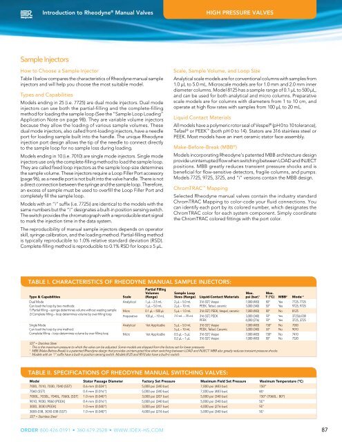
TABLE I. CHARACTERISTICS OF RHEODYNE MANUAL SAMPLE INJECTORS:<br />
Type & Capabilities<br />
<br />
<br />
<br />
<br />
<br />
<br />
<br />
Scale<br />
<br />
Partial Filling<br />
Volumes<br />
(Range)<br />
<br />
<br />
Sample Loop<br />
Sizes (Range)<br />
<br />
<br />
Liquid-Contact Materials<br />
<br />
<br />
Max.<br />
psi (bar) 1<br />
<br />
<br />
Max.<br />
T (ºC) MBB 2 Model 3<br />
<br />
<br />
<br />
<br />
<br />
<br />
<br />
<br />
<br />
<br />
<br />
<br />
<br />
<br />
<br />
<br />
<br />
SST = Stainless Steel<br />
1<br />
This is the maximum pressure to which the valve can be adjusted. Some models are shipped from the factory set for lower pressures.<br />
2<br />
MBB(Make-Before-Break) is a patented Rheodyne design that provides uninterrupted flow when switching between LOAD and INJECT. MBB also greatly reduces transient pressure shocks.<br />
3<br />
Models with an “i” suffix have a built-in position sensing switch. Models 8125 and 9010 also have a built-in switch.<br />
<br />
<br />
<br />
<br />
<br />
<br />
<br />
<br />
<br />
<br />
<br />
<br />
<br />
<br />
<br />
<br />
<br />
<br />
<br />
<br />
<br />
<br />
<br />
<br />
TABLE II. SPECIFICATIONS OF RHEODYNE MANUAL SWITCHING VALVES:<br />
Model Stator Passage Diameter Factory Set <strong>Pressure</strong> Maximum Field Set <strong>Pressure</strong> Maximum Temperature (ºC)<br />
<br />
<br />
<br />
<br />
<br />
<br />
SST = Stainless Steel<br />
ORDER<br />
87