
You also want an ePaper? Increase the reach of your titles
YUMPU automatically turns print PDFs into web optimized ePapers that Google loves.
HIGH PRESSURE VALVES<br />
Introduction to Rheodyne ® Manual <strong>Valves</strong><br />
<strong>High</strong> <strong>Pressure</strong> Switching <strong>Valves</strong><br />
Rheodyne offers high pressure manual switching valves to simplify<br />
procedures and improve the speed, resolution, and sensitivity of<br />
<br />
and PEEK , with a choice of 1.6 mm (1/16”) or 3.2 mm (1/8”) ports.<br />
See Table II on page 87 for valve specifications.<br />
Column Selection<br />
The six-position switching valves are used for column selection. These<br />
valves substitute one column for another without the need to manually<br />
disconnect the plumbing. This makes it easy to designate a separate<br />
column for each analysis, which helps eliminate equilibration delays,<br />
reduce interferences and prolong column life. Turning the valve handle<br />
selects the column desired for a particular analysis. Columns switched<br />
to off-line are automatically sealed at both ends.<br />
Column Switching<br />
The two-position switching valves can be used to reroute mobile<br />
phase during the chromatographic run without changing separation<br />
techniques. They can also be used to perform sequential separations<br />
with different columns and/or mobile phases.<br />
Although the model 7000 is the most commonly used and versatile<br />
switching valve, other models have specific uses such as for three-way<br />
or four-way switching patterns.<br />
Many models have flow passages available in both standard bore and<br />
large bore (designated with an “L” suffix). L models use 1/16” fittings<br />
and tubing but have larger flow passage diameters than non-L models.<br />
As such, L models can accommodate higher flow rates. Large bore<br />
tubing can be used when the pressure drop must be limited. Large bore<br />
valves have a lower pressure drop than standard bore valves when both<br />
valve sizes accommodate the same flow rate (see graph below).<br />
Effects of <strong>Valves</strong> and Tubing on Resolution<br />
The effect of tubing on analytical and microscale analyses can be<br />
significant. Since dispersion caused by tubing is proportional to the<br />
fourth power of diameter, large bore tubing should be avoided when<br />
performing analytical scale or microscale analyses. Tubing ID size<br />
≤ 0.25 mm (0.010”) is recommended.<br />
Consider a system with a Rheodyne injector and column switching<br />
valves and analytical columns with small-bore connecting tubing.<br />
The chromatograms below, made using a typical analytical<br />
chromatograph, show these effects. Scheme A is the control<br />
(injector column detector) with no valve in the system. In Schemes<br />
B and C, two model 7060 Six-Position Switching <strong>Valves</strong> were placed<br />
side by side (injector valve #1 column valve #2 detector).<br />
The injector and detector were connected to these valves by the same<br />
tubing used in the control. The extra tubing pieces required to connect<br />
the valves to the column were a 10 cm length for valve #1-to-column,<br />
and a 35 cm length for column-to-valve #2. The diameters of these<br />
tubes are indicated in the experimental details, below.<br />
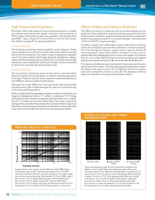
EFFECTS OF VALVES AND TUBING<br />
ON RESOLUTION:<br />
PRESSURE DROP VS. FLOW RATE:<br />
<br />
<br />
<br />
<strong>Pressure</strong> Drop (psi)<br />
1<br />
<br />
<br />
1 <br />
Flow Rate (mL/min)<br />
<strong>Pressure</strong> drop vs. flow rate for model 7000 and model 7000L (largebore)<br />
valves; water at 20°C. Experimental measurements: The flow<br />
channel is one stator inlet port, one rotor seal groove, one stator outlet<br />
port and two connecting tubes. Solid squares = (1.0 mm 7000L valve) +<br />
<br />
(two 1.0 mm x 5.0 cm tubes). Cross mark = (0.6 mm 7000 valve) +<br />
(two 0.5 mm x 5.0 cm tubes). Solid lines are theoretical values for 10 cm<br />
long tubes of 1.0 mm and 0.5 mm ID. <strong>Pressure</strong> drop is in units of psi.<br />
A Column Only B Valve w/ 0.007” C Valve w/ 0.020”<br />
Tubing<br />
Tubing<br />
These chromatograms show the loss of resolution caused by the<br />
addition of two model 7060 column selection valves when using<br />
connection tubes of two different inside diameters. Conditions for all<br />
cases: 4.6 mm x 12.5 cm column, 5 µm C-18 packing, 50% acetonitrile<br />
in water, 2.0 mL/min, 21°C, 5.0 µL sample partial filled into a model<br />
7125 injector, 10 cm x 0.18 mm (0.007”) bore injector outlet tube<br />
(to column or valve), 10 cm x 0.18 mm bore detector inlet tube<br />
(from column or valve), low dispersion 1.0 cm path UV detector cell,<br />
0.2 sec detector time constant. See text above for details.<br />
88<br />
ORDER