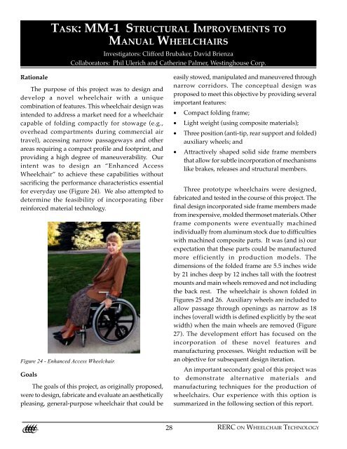
MM-1 Structural Improvements to Manual Wheelchairs
MM-1 Structural Improvements to Manual Wheelchairs
MM-1 Structural Improvements to Manual Wheelchairs

Create successful ePaper yourself
Turn your PDF publications into a flip-book with our unique Google optimized e-Paper software.
TASK: <strong>MM</strong>-1 STRUCTURAL IMPROVEMENTS TO<br />
MANUAL WHEELCHAIRS<br />
Investiga<strong>to</strong>rs: Clifford Brubaker, David Brienza<br />
Collabora<strong>to</strong>rs: Phil Ulerich and Catherine Palmer, Westinghouse Corp.<br />
Rationale<br />
The purpose of this project was <strong>to</strong> design and<br />
develop a novel wheelchair with a unique<br />
combination of features. This wheelchair design was<br />
intended <strong>to</strong> address a market need for a wheelchair<br />
capable of folding compactly for s<strong>to</strong>wage (e.g.,<br />
overhead compartments during commercial air<br />
travel), accessing narrow passageways and other<br />
areas requiring a compact profile and footprint, and<br />
providing a high degree of maneuverability. Our<br />
intent was <strong>to</strong> design an “Enhanced Access<br />
Wheelchair” <strong>to</strong> achieve these capabilities without<br />
sacrificing the performance characteristics essential<br />
for everyday use (Figure 24). We also attempted <strong>to</strong><br />
determine the feasibility of incorporating fiber<br />
reinforced material technology.<br />
Figure 24 - Enhanced Access Wheelchair.<br />
Goals<br />
The goals of this project, as originally proposed,<br />
were <strong>to</strong> design, fabricate and evaluate an aesthetically<br />
pleasing, general-purpose wheelchair that could be<br />
easily s<strong>to</strong>wed, manipulated and maneuvered through<br />
narrow corridors. The conceptual design was<br />
proposed <strong>to</strong> meet this objective by providing several<br />
important features:<br />
• Compact folding frame;<br />
• Light weight (using composite materials);<br />
• Three position (anti-tip, rear support and folded)<br />
auxiliary wheels; and<br />
• Attractively shaped solid side frame members<br />
that allow for subtle incorporation of mechanisms<br />
like brakes, releases and structural members.<br />
Three pro<strong>to</strong>type wheelchairs were designed,<br />
fabricated and tested in the course of this project. The<br />
final design incorporated side frame members made<br />
from inexpensive, molded thermoset materials. Other<br />
frame components were eventually machined<br />
individually from aluminum s<strong>to</strong>ck due <strong>to</strong> difficulties<br />
with machined composite parts. It was (and is) our<br />
expectation that these parts could be manufactured<br />
more efficiently in production models. The<br />
dimensions of the folded frame are 5.5 inches wide<br />
by 21 inches deep by 12 inches tall with the footrest<br />
mounts and main wheels removed and not including<br />
the back rest. The wheelchair is shown folded in<br />
Figures 25 and 26. Auxiliary wheels are included <strong>to</strong><br />
allow passage through openings as narrow as 18<br />
inches (overall width is defined explicitly by the seat<br />
width) when the main wheels are removed (Figure<br />
27). The development effort has focused on the<br />
incorporation of these novel features and<br />
manufacturing processes. Weight reduction will be<br />
an objective for subsequent design iteration.<br />
An important secondary goal of this project was<br />
<strong>to</strong> demonstrate alternative materials and<br />
manufacturing techniques for the production of<br />
wheelchairs. Our experience with this option is<br />
summarized in the following section of this report.<br />
28 RERC ON WHEELCHAIR TECHNOLOGY
Figure 25. - Side view of folded wheelchair.<br />
Methods<br />
A CAD design for the pro<strong>to</strong>type wheelchair was<br />
executed using CADKEY. This design was exported<br />
<strong>to</strong> a more sophisticated CAD system at Westinghouse<br />
Corp. Science and Technology Center where the<br />
design was further refined. A structural analysis<br />
using ANSYS, a finite element analysis program, was<br />
conducted <strong>to</strong> determine the necessary material<br />
strengths for the different parts. Stress analyses were<br />
performed on individual components and for an<br />
articulated model of the prospective pro<strong>to</strong>type. Upon<br />
completion of the design and computer simulation<br />
phases, the project proceeded <strong>to</strong> the development of<br />
the physical pro<strong>to</strong>type. Thermoset materials were<br />
considered as a low-cost production option for<br />
wheelchair structures.<br />
Inexpensive, molded thermoset materials offer<br />
several advantages for use as low cost wheelchair<br />
structures. Two major disadvantages are<br />
manufacturers’ lack of experience with thermoset<br />
molding and the high initial cost of molds. Both of<br />
these problems were considered in this project.<br />
The structural elements of the wheelchair were<br />
designed as compression molded, glass filled<br />
polyester components. One reason for this selection<br />
is the very low cost of this material. It is used<br />
commonly in industry for electrically insulated<br />
structural parts. Since it is an engineered plastic, an<br />
entire range of material strengths, weights and costs<br />
are available. This allows for trade-off between<br />
weight and cost in the design and manufacture of<br />
wheelchairs. The basic design and geometry of this<br />
wheelchair was defined substantially by the novel<br />
folding mechanism of the chair and by common<br />
structural requirements for wheelchairs.<br />
A few iterations of weight reduction analysis were<br />
done on the parts <strong>to</strong> save some material. Considerably<br />
more refinement is possible. The chair was modeled<br />
as plate elements and loaded with a 200 kg dummy<br />
at 3 g’s. Consideration was given <strong>to</strong> both the<br />
maximum von Mises stress and the maximum<br />
deflection. Acceptable deflection was based only on<br />
assumed aesthetic perceptions for the pro<strong>to</strong>type<br />
development. The stress limit was determined from<br />
isotropic treatment of the maximum allowable tensile<br />
stress.<br />
Figure 26 - Folded (front).<br />
The high cost of mold fabrication precluded mold<br />
development for parts other than the side frame. Parts<br />
were initially machined from sheet s<strong>to</strong>ck. This<br />
decision was made with the knowledge that<br />
machined composite parts typically have structural<br />
strengths on the order of 40% less than comparable<br />
FINAL REPORT: 1993-1998<br />
29
molded parts. This loss of strength is well<br />
documented and results from surface cracks and<br />
defects left from milling the smooth, fiber free<br />
surfaces. The use of machined composite parts proved<br />
not <strong>to</strong> be a viable solution in subsequent testing. The<br />
parts (other than the side panels) were subsequently<br />
machined from aluminum sheet and bar s<strong>to</strong>ck.<br />
Figure 27 - Side view with main wheels removed.<br />
The molding technology chosen for this project<br />
is based on spray metal <strong>to</strong>oling. This technique for<br />
mold making takes about a month and costs less than<br />
$8,000. This process is rather new and has seldom<br />
been used on compression molded parts of this size.<br />
Only 20 <strong>to</strong> 150 parts would be expected from this <strong>to</strong>ol.<br />
By contrast, standard mold construction (using steel)<br />
for comparable sized parts would require 4 <strong>to</strong> 6<br />
months <strong>to</strong> complete at a cost on the order of $70,000.<br />
These steel molds could be used <strong>to</strong> produce 500,000<br />
<strong>to</strong> 5,000,000 parts. Standard aluminum molds are less<br />
expensive ($45,000), quicker <strong>to</strong> machine<br />
(approximately 3 months), and would be suitable for<br />
producing 5,000 <strong>to</strong> 25,000 parts. The project provided<br />
an opportunity <strong>to</strong> consider the efficacy of<br />
compression molded parts at modest cost.<br />
The mold was fabricated over the course of 8<br />
weeks and was received at Penn Compression near<br />
Pittsburgh, PA. The mold was made from a wood<br />
model of the final part, which was placed in an inert<br />
bed up <strong>to</strong> the mold parting line. An electric spray head<br />
was used <strong>to</strong> sputter-coat thin layers of a zincaluminum<br />
alloy on<strong>to</strong> the pattern. Zinc-aluminum<br />
wire is fed in<strong>to</strong> the spray head and electrically melted.<br />
Repeated layers of sprayed metal were applied until<br />
a shell was created from 1/8 <strong>to</strong> 1/4 inch thick. This<br />
shell was backed with an aluminum-filled epoxy <strong>to</strong><br />
provide strength and stiffness and placed in<strong>to</strong> a cold<br />
rolled steel frame about 1/2 inch thick. This process<br />
was repeated <strong>to</strong> form the other half of the mold.<br />
Unfortunately, the mold was incorrectly developed<br />
as a conventional injection mold, rather than as a<br />
compression mold. For injection molding the mold<br />
is parted at the midline with two symmetrical (in this<br />
instance) halves that are held in opposition while<br />
material is injected. In contrast, a compression mold<br />
has a “force” component and a “cavity” component<br />
as the two “halves.” Without a force and cavity, it<br />
was difficult <strong>to</strong> assure that sufficient material would<br />
be incorporated in<strong>to</strong> the mold <strong>to</strong> fill the part. After<br />
six attempts the proper charge of bulk molded<br />
material <strong>to</strong> fill the part was determined. After the<br />
third piece was molded, the ejec<strong>to</strong>r system failed and<br />
the molder was forced <strong>to</strong> pry subsequent pieces out<br />
of the mold using hand <strong>to</strong>ols. This was difficult, as<br />
the mold must be stabilized at 350 degrees before the<br />
molding process can begin. The failure required a<br />
modification of the mold. It became necessary <strong>to</strong><br />
machine away extra material. This ultimately<br />
weakened the parts.<br />
Figure 28 - Narrow access.<br />
30 RERC ON WHEELCHAIR TECHNOLOGY
The molded side-frame had four “through<br />
holes,”including a 1" diameter main axle hole and<br />
three 1/4 inch diameter holes <strong>to</strong> s<strong>to</strong>p the auxiliary<br />
wheel in its various positions. Of the parts produced,<br />
five did not fill completely and several others were<br />
broken while being ejected from the <strong>to</strong>ol. In the end,<br />
six acceptable parts were made, allowing for the<br />
assembly of three pro<strong>to</strong>types.<br />
Pro<strong>to</strong>type assembly<br />
Fabrication of an initial pro<strong>to</strong>type resulted in the<br />
discovery of weaknesses in the original design. As a<br />
result of the initial fabrication phase, a substantial<br />
number of the components were redesigned with the<br />
goal of increasing the structural integrity of the<br />
wheelchair frame. The modified designs were used<br />
<strong>to</strong> fabricate two additional pro<strong>to</strong>types, which were<br />
evaluated using applicable ISO standard test<br />
procedures. The modified version is shown in Figure<br />
29 and 30.<br />
Figure 29 - Assembled Pro<strong>to</strong>type.<br />
ISO Test Evaluation of the pro<strong>to</strong>type<br />
The first of the modified pro<strong>to</strong>types was tested<br />
according <strong>to</strong> ISO 7176-8 (<strong>Wheelchairs</strong> - Part 8:<br />
Requirements and test methods for static, impact and<br />
fatigue strength). The chair passed all static and<br />
impact strength tests with the exception of armrest<br />
upward weight bearing. The armrest upward force<br />
test is not applicable <strong>to</strong> our design since the armrests<br />
were designed <strong>to</strong> release with upward force. The chair<br />
successfully completed 200,000 cycles on the twodrum<br />
fatigue strength test without failure, but failed<br />
after 2055 cycles of the curb drop test. This failure<br />
was a fracture of the side frame where the footrest<br />
and front caster wheels are attached. Prior <strong>to</strong> the<br />
testing, we observed cracks in the frame resulting<br />
from a poor fit between the molded side frame and<br />
the footrest/caster wheel mount. It will be necessary<br />
<strong>to</strong> address this area of structural weakness in the<br />
design of future pro<strong>to</strong>types using molded<br />
components.<br />
Consumer Evaluation of the Pro<strong>to</strong>type<br />
Initial evaluation was provided by an<br />
experienced wheelchair user and resulted in several<br />
comments and suggestions:<br />
• The concept of the design is attractive. The ability<br />
<strong>to</strong> remove the rear wheels and use 8 inch auxiliary<br />
wheels <strong>to</strong> roll down an airplane aisle or in a small<br />
rest room would be useful. (Figure 28)<br />
• The ability of the chair <strong>to</strong> fold and break-down<br />
in<strong>to</strong> small components makes it attractive for<br />
s<strong>to</strong>ring in overhead compartments of aircraft or<br />
in compact au<strong>to</strong>mobiles.<br />
• The folding mechanism is awkward and<br />
cumbersome. The wheelchair can become difficult<br />
<strong>to</strong> fold if the central pin loses alignment with the<br />
cross-braces. The dovetail joints bind and are<br />
prone <strong>to</strong> jamming from dust and dirt.<br />
• The wheelchair is much <strong>to</strong>o heavy. The materials<br />
need <strong>to</strong> be changed and the overall design<br />
lightened.<br />
• The wheelchair is <strong>to</strong>o tall and the leg rests are<br />
positioned <strong>to</strong>o far forward.<br />
• The auxiliary wheels do not perform adequately<br />
as anti-tip devices and are cumbersome <strong>to</strong> use.<br />
• The wheelchair and center of gravity are not<br />
adequately adjustable.<br />
• The backrest folding mechanism is bulky and<br />
does not provide adequate lateral stiffness.<br />
FINAL REPORT: 1993-1998<br />
31
• The chair has multiple pinch points that need <strong>to</strong><br />
be eliminated<br />
• The wheelchair provides a proof-of-concept and<br />
would require additional refinement prior <strong>to</strong><br />
being acceptable <strong>to</strong> consumers.<br />
wheelchair that allows access <strong>to</strong> narrow corridors and<br />
is rigid and durable enough for everyday use is now<br />
several years old, there is still considerable need for<br />
such a product by many wheelchair users. As a result,<br />
we feel that the market potential for a wheelchair with<br />
these features is still significant. This initial funding<br />
provided the basis <strong>to</strong> take the most critical step in the<br />
research and development process: from conceptual<br />
design <strong>to</strong> full-scale working pro<strong>to</strong>type. There are still<br />
several important engineering problems <strong>to</strong> solve<br />
before the eventual development of a commercial<br />
product; however, we have successfully<br />
demonstrated the feasibility of producing the<br />
wheelchair for enhanced access. Although it was not<br />
our primary objective, we have also shown the<br />
possibility of using parts manufactured with<br />
inexpensive techniques and materials.<br />
External Evaluation<br />
Figure 30 - Front view of assembly<br />
Several of these problems have already been<br />
addressed. For example, the seat was redesigned <strong>to</strong><br />
eliminate the possibility of pinching while it is being<br />
opened. The backrest support brackets were<br />
redesigned since this initial evaluation was made.<br />
Amelioration of all other shortcomings is being<br />
considered. The design will require further iteration<br />
<strong>to</strong> become viable for commercial development.<br />
Outcomes Summary<br />
Our initial impression of the pro<strong>to</strong>type relative<br />
<strong>to</strong> its performance is positive. The solid seat <strong>to</strong>gether<br />
with the cross braces and side frame members form<br />
a support structure that feels significantly more rigid<br />
than typical “X” cross brace frame, folding<br />
wheelchairs. Even with the large main wheels<br />
removed for narrow access, the wheelchair was<br />
sturdy and stable. In informal trials in our labora<strong>to</strong>ry,<br />
varying users have found the chair’s performance <strong>to</strong><br />
exceed their expectations for a folding frame<br />
wheelchair. A formal beta test program will be<br />
developed as the next stage of development.<br />
Although the concept of a compactly folding<br />
A more thorough demonstration and evaluation<br />
was conducted by the RERC on Technology Transfer<br />
at SUNY Buffalo. The Enhanced Access Wheelchair<br />
was evaluated by three focus groups of 30 consumers<br />
who had used a manual wheelchair for a minimum<br />
of five years. Some general results from comparisons<br />
with existing commercial products were particularly<br />
encouraging:<br />
1. 55% of the consumer participants preferred the<br />
pro<strong>to</strong>type <strong>to</strong> existing products.<br />
2. Consumers were willing <strong>to</strong> pay up <strong>to</strong> $200 more<br />
for the features incorporated in the Enhanced<br />
Access Pro<strong>to</strong>type.<br />
3. Consumers increased the additional amount they<br />
would pay for the pro<strong>to</strong>type features <strong>to</strong> $370<br />
(mean) after viewing the features of a competing,<br />
production model wheelchair.<br />
4. Among features valued by the consumers were<br />
the folding mechanism, the folded size, and the<br />
3-position deployment of the auxiliary wheels, the<br />
“solid” seat, and the aesthetics of the side-frame.<br />
Disadvantages identified included the<br />
imprecision and “awkwardness” of the<br />
mechanisms, the overall weight, and the lack of<br />
tie-down points. Suggestions were generally on<br />
ways <strong>to</strong> improve the mechanisms and decrease<br />
32 RERC ON WHEELCHAIR TECHNOLOGY
the weight. One of the strongest preferences for<br />
the pro<strong>to</strong>type over production folding chairs was<br />
the folding mechanism. It was perceived <strong>to</strong> be<br />
more stable and <strong>to</strong> allowed more compact folding.<br />
Recommendations for Future Development<br />
The project has progressed <strong>to</strong> the point of<br />
successful demonstration of several valuable features<br />
of a manual wheelchair. We believe that the<br />
evaluation information is sufficiently positive <strong>to</strong><br />
warrant further development. Initial plans for a<br />
second generation pro<strong>to</strong>type have been completed.<br />
We believe that it will be necessary <strong>to</strong> produce a metal<br />
frame model <strong>to</strong> gain the interest of current<br />
manufacturers. If we can obtain additional funding<br />
for this project we shall proceed with development<br />
of an all metal pro<strong>to</strong>type in which we shall refine the<br />
mechanisms and reduce the weight of the wheelchair<br />
as suggested by the consumer panels.<br />
Publications and Technical Reports<br />
Brienza, DM, CE Brubaker (1996) Design and Development<br />
of a Wheelchair for Enhanced Access, RESNA Proceedings,<br />
16:250-252.<br />
Brubaker CE, Brienza DM, Ulerich P “Design and<br />
Development of a Wheelchair for Enhanced Access,” Final<br />
Progress Report, SCRF Grant #1218, Paralyzed Veterans<br />
of America, November 10, 1995.<br />
Ulerich P, Palmer, K, Stampahar,M, Brubaker, CE “Design<br />
and Development of a Wheelchair for Enhanced Access,”<br />
First Annual Report <strong>to</strong> the Paralyzed Veterans of America<br />
Spinal Cord Research Foundation, Grant #1218-01, March<br />
16, 1994.<br />
FINAL REPORT: 1993-1998<br />
33