View - PTC Community
View - PTC Community
View - PTC Community

Create successful ePaper yourself
Turn your PDF publications into a flip-book with our unique Google optimized e-Paper software.
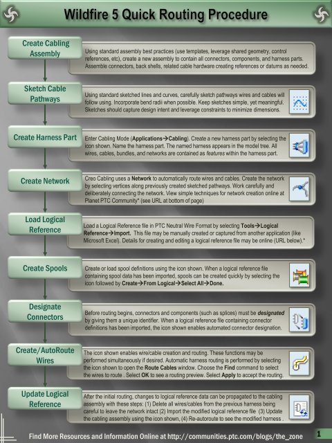
Create Cabling<br />
Assembly<br />
Using standard assembly best practices (use templates, leverage shared geometry, control<br />
references, etc), create a new assembly to contain all connectors, components, and harness parts.<br />
Assemble connectors, back shells, related cable hardware creating references or datums as needed.<br />
Sketch Cable<br />
Pathways<br />
Using standard sketched lines and curves, carefully sketch pathways wires and cables will<br />
follow using. Incorporate bend radii when possible. Keep sketches simple, yet meaningful.<br />
Sketches should capture design intent and leverage constraints to minimize dimensions.<br />
Create Harness Part<br />
Enter Cabling Mode (ApplicationsCabling). Create a new harness part by selecting the<br />
icon shown. Name the harness part. The named harness appears in the model tree. All<br />
wires, cables, bundles, and networks are contained as features within the harness part.<br />
Create Network<br />
Load Logical<br />
Reference<br />
Creo Cabling uses a Network to automatically route wires and cables. Create the network<br />
by selecting vertices along previously created sketched pathways. Work carefully and<br />
deliberately connecting the network. <strong>View</strong> simple techniques for network creation online at<br />
Planet <strong>PTC</strong> <strong>Community</strong>* (see URL at bottom of page)<br />
Load a Logical Reference file in <strong>PTC</strong> Neutral Wire Format by selecting ToolsLogical<br />
ReferenceImport. This file may be manually created or captured from another application (like<br />
Microsoft Excel). Details for creating and editing a logical reference file may be online (URL below).*<br />
Create Spools<br />
Create or load spool definitions using the icon shown. When a logical reference file<br />
containing spool data has been imported, spools can be created quickly by selecting the<br />
icon followed by CreateFrom LogicalSelect AllDone.<br />
Designate<br />
Connectors<br />
Before routing begins, connectors and components (such as splices) must be designated<br />
by giving them a unique identifier. When a logical reference file containing connector<br />
definitions has been imported, the icon shown enables automated connector designation.<br />
Create/AutoRoute<br />
Wires<br />
Update Logical<br />
Reference<br />
The icon shown enables wire/cable creation and routing. These functions may be<br />
performed simultaneously if desired. Automatic harness routing is performed by selecting<br />
the icon shown to open the Route Cables window. Choose the Find command to select<br />
the wires to route . Select OK to see a routing preview. Select Apply to accept the routing.<br />
After the initial routing, changes to logical reference data can be propagated to the cabling<br />
assembly with these steps: (1) Delete all wires/cables from the previous harness being<br />
careful to leave the network intact (2) Import the modified logical reference file (3) Update<br />
the cabling assembly using the icon shown, (4) Re-autoroute to see the modified harness .<br />
Find More Resources and Information Online at http://communities.ptc.com/blogs/the_zone<br />
1
Environment<br />
Tools<br />
Cable & Network Operations<br />
Ref Designators On/Off<br />
Show Thin Cables<br />
(Shows Networks)<br />
Show Thick Cables<br />
(Hides Networks)<br />
Internal Routing On/Off<br />
Compare Logical Reference<br />
Update Logical Reference<br />
Network Tools Fly Out<br />
Network Tools Fly Out<br />
Check Continuity<br />
(Find Disconnections)<br />
Check Locations<br />
(Find Overlapping Locations)<br />
Create/Edit Harness Fly Out<br />
Create/Edit Spools<br />
Insert Splice/Component<br />
Auto Designate Connectors<br />
Create/Edit Harness Fly Out<br />
Modify/Edit Harness<br />
Create New Harness<br />
Route Wires/Cables<br />
Route Network<br />
Add Location<br />
Bundle Operations<br />
Cosmetic Features Fly Out<br />
Cosmetic Features Fly Out<br />
Create Marker<br />
Create Tape Feature<br />
Create Tie Wrap<br />
2