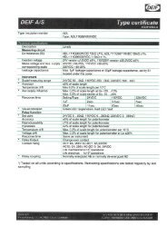
Genset Controller, GC-1F
Genset Controller, GC-1F
Genset Controller, GC-1F

You also want an ePaper? Increase the reach of your titles
YUMPU automatically turns print PDFs into web optimized ePapers that Google loves.
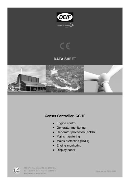
DATA SHEET<br />
<strong>Genset</strong> <strong>Controller</strong>, <strong>GC</strong>-<strong>1F</strong><br />
• Engine control<br />
• Generator monitoring<br />
• Generator protection (ANSI)<br />
• Mains monitoring<br />
• Mains protection (ANSI)<br />
• Engine monitoring<br />
• Display panel<br />
Document no.: 4921240310I
Data sheet Gen-set <strong>Controller</strong> <strong>GC</strong>-<strong>1F</strong><br />
This data sheet includes the following versions:<br />
<strong>GC</strong>-<strong>1F</strong> SW version 1.2x.x<br />
<strong>GC</strong>-<strong>1F</strong>/2 SW version 2.0x.x or later<br />
DEIF A/S Page 2 of 13
Data sheet Gen-set <strong>Controller</strong> <strong>GC</strong>-<strong>1F</strong><br />
Application<br />
The Gen-set <strong>Controller</strong> <strong>GC</strong>-<strong>1F</strong> is a microprocessorbased<br />
control unit containing all necessary functions for<br />
protection and control of a diesel engine. Furthermore,<br />
it contains a three-phase AC voltage measuring circuit.<br />
The unit is equipped with an LCD display presenting all<br />
values and alarms. <strong>GC</strong>-<strong>1F</strong> is a compact all-in-one unit<br />
designed for the following applications:<br />
1. Automatic engine start/stop<br />
2. Engine protection<br />
3. Breaker control<br />
4. Generator protection<br />
5. Automatic Mains Failure<br />
6. Automatic Transfer Switch control*<br />
<strong>GC</strong>-<strong>1F</strong> automatically carries out a cyclical self test. If<br />
any errors are found, the status relay output will<br />
deactivate (normally closed). In order to save battery<br />
power, the display can be set to switch off automatically<br />
after a given period of time. The display will turn on<br />
again, if events or alarms take place, or if one of the<br />
push-buttons is activated.<br />
Terminals<br />
Setup<br />
Setup is easily done via a PC Windows ® based utility<br />
software (password-protected). A PC interface box is<br />
needed for this operation (option J5). Option J5 is<br />
optional equipment for <strong>GC</strong>-<strong>1F</strong>. The PC utility software<br />
offers additional features such as monitoring of all<br />
relevant information during commissioning, saving and<br />
downloading of settings and downloading of software<br />
updates. Furthermore, the most frequently used<br />
settings can be accessed via the display push-buttons<br />
(password-protected).<br />
Language<br />
Master language is English and furthermore, there are<br />
three selectable languages. These are listed in the<br />
order specification.<br />
Translation<br />
This function makes it possible to change all texts used<br />
in the unit.<br />
Options<br />
The options selected by the customer will be integrated<br />
in the standard <strong>GC</strong>-<strong>1F</strong>, hereby securing the same user<br />
interface unaffected by whether the application needs a<br />
basic or a more complex gen-set controller.<br />
Terminal Technical data Description<br />
1 Power supply + Aux. supply<br />
2 Power supply – GND<br />
3-4<br />
Status out/configurable. Contact ratings 1 A 24V DC/V<br />
AC Resistive<br />
General status output for marine approvals/only configurable in<br />
hw 1.05 and sw 2x.x.<br />
9 Common Common for term. 10…15<br />
10 Digital input Start enable/configurable<br />
11 Digital input Remote start/stop/configurable<br />
12 Digital input Charge alternator D+ (running)/configurable<br />
13 Digital input Configurable<br />
14 Digital input Coolant temperature/configurable<br />
15 Digital input Oil pressure/configurable<br />
19 Common Common for emergency stop term. 20<br />
20 Emergency stop and common for 21…23 Common for relays 1, 2 and 3 and input for emergency stop*<br />
21 Relay output 21. Start prepare/configurable. Function NO<br />
22 Relay output 22. Starter (crank)/configurable. Function NO<br />
23 Relay output 23. Run coil/configurable. Function NO<br />
24-25 Relay output 24. Horn/configurable. Function NO<br />
26-27 Relay output 26. Alarm/configurable. Function NO<br />
5 Common<br />
Multi-functional inputs<br />
Common for term. 6…8<br />
6 VDO1/0(4)...20 mA/binary input Fuel level/configurable<br />
7 VDO2/0(4)...20 mA/binary input Oil pressure/configurable<br />
8 VDO3/0(4)...20 mA/binary input Water temp./configurable<br />
Tacho RPM input<br />
16 RPM input Magnetic pick-up/tacho generator<br />
17 RPM-GND Common for RPM input<br />
18 RPM input W Magnetic pick-up. PNP, NPN or charge alternator W terminal<br />
* Only possible with HW 1.05 and SW 2.2x.x.<br />
DEIF A/S Page 3 of 13
Data sheet Gen-set <strong>Controller</strong> <strong>GC</strong>-<strong>1F</strong><br />
3-phase generator voltage input<br />
33 Gen. voltage L1<br />
34 Gen. neutral<br />
35<br />
36<br />
Not used, must not be connected<br />
Gen. voltage L2<br />
Generator voltage and frequency<br />
37 Not used, must not be connected<br />
38 Gen. voltage L3<br />
3-phase generator current input<br />
39 Gen. current L1, s1<br />
40 Gen. current L1, s2<br />
41<br />
42<br />
Gen. current L2, s1<br />
Gen. current L2, s2<br />
Generator current<br />
43 Gen. current L3, s1<br />
44 Gen. current L3, s2<br />
3-phase mains voltage inputs<br />
28 Mains voltage L1<br />
29 Mains voltage neutral<br />
30 Mains voltage L2<br />
31 Not used, must not be connected<br />
32 Mains voltage L3<br />
Breaker relays<br />
45<br />
Relay R45.<br />
Generator circuit breaker/configurable, function NO (normally<br />
46 Relay R45<br />
open)<br />
47<br />
Relay R47.<br />
Optional relay for closing mains breaker (option B3)<br />
Mains circuit breaker/configurable, function NC (normally closed).<br />
48 Relay R47<br />
Optional relay NO contact (option M19)<br />
47<br />
Relay R47. Contact ratings 2 A 30V DC/250V AC<br />
(UL/cUL Listed: Contact ratings 2 A 30V DC/30V AC) Mains circuit breaker/configurable, function NO (normally open)<br />
48 Relay R47<br />
Optional Modbus RS485 interface (option H2)<br />
49 B (-)<br />
50 GND<br />
Modbus RS485 RTU or ASCII<br />
51 A (+)<br />
Optional CANbus #1 engine interface<br />
53 CAN-H<br />
54 CAN-GND<br />
CAN J1939 engine communication<br />
55 CAN-L<br />
Optional CANbus #2 AOP-2 interface (option X4)<br />
57 CAN-H<br />
58 CAN-GND<br />
CAN communication line to AOP-2<br />
59 CAN-L<br />
Optional CANbus #2 ext. I/O interface (option H8)<br />
57 CAN-H<br />
58 CAN-GND<br />
CAN communication line to external I/O<br />
59<br />
CAN-L<br />
DEIF A/S Page 4 of 13
Data sheet Gen-set <strong>Controller</strong> <strong>GC</strong>-<strong>1F</strong><br />
Available options<br />
Option Description Type Note<br />
B Generator protection<br />
B3 Automatic Mains Failure and ATS control<br />
- Generator and mains breaker control<br />
- Change-over (no synchronisation)<br />
G Breaker<br />
G6 Front layout with generator breaker Hardware option<br />
H Communication<br />
H2 Modbus RS485 RTU or ASCII Hardware option<br />
Hardware option ATS mode is only available<br />
in HW 1.05 and SW 2.2x.x.<br />
Option B3 must also be<br />
set.<br />
H5 CANbus J1939 CANbus #1 comm.<br />
Hardware option<br />
- Detroit Diesel<br />
- John Deere<br />
- Deutz<br />
- Volvo Penta EMS<br />
- Volvo Penta EMS 2<br />
- Scania EMS<br />
- Scania EMS 2<br />
- MTU MDEC 302<br />
- MTU MDEC 303<br />
- MTU ADEC<br />
- Cummins<br />
- Iveco<br />
- Perkins<br />
- Caterpillar<br />
H8 External I/O CANbus #2 comm. Hardware option See supported modules in<br />
option H8 documentation<br />
J Cables<br />
J5 PI-1 converter box kit (for PC connection) Hardware option<br />
K Documentation<br />
K1 Installation Instructions and Reference Handbook (hard copy) Other<br />
K2 CD-ROM with complete documentation Other<br />
L Gasket for IP65 Hardware option<br />
M<br />
L2 Heatfoil for display (display will operate down to -40°C) Hardware option Only HW 1.05 and ASW<br />
2.0x.x<br />
M19 Mains circuit breaker/configurable, contact function NO (normally<br />
open)<br />
X Display<br />
X4 Additional operator panel (AOP-2): 16 configurable LEDs, 8 configurable<br />
buttons and 1 status relay. CANbus #2 comm.<br />
Y Folio<br />
Hardware option Only HW 1.05 and ASW<br />
2.2x.x<br />
Hardware option Maximum of 2 AOP2s<br />
Y2 Engine folio without generator symbol, generator and mains breaker Hardware option<br />
Y10 Source – source folio with breaker symbols Hardware option Only HW 1.05 and ASW<br />
2.2x.x<br />
DEIF A/S Page 5 of 13
Data sheet Gen-set <strong>Controller</strong> <strong>GC</strong>-<strong>1F</strong><br />
Option B3 display layout<br />
AUT TEST<br />
Option Y10 Source – Source display layout<br />
DEIF A/S Page 6 of 13<br />
ESC
Data sheet Gen-set <strong>Controller</strong> <strong>GC</strong>-<strong>1F</strong><br />
F: Fuse: Min. 2 A slow-blow.<br />
Wiring, engine interface<br />
It is possible to combine VDO inputs with binary and 0(4)…20 mA inputs in a mix.<br />
DEIF A/S Page 7 of 13
Data sheet Gen-set <strong>Controller</strong> <strong>GC</strong>-<strong>1F</strong><br />
Connection of the 3-phase voltage and current<br />
GB<br />
CONSUMER<br />
N L1<br />
S2<br />
S1<br />
N L1<br />
Generator<br />
L2 L3<br />
Wiring, AC interface<br />
The AC current grounding can be made as required to s1 or s2.<br />
GB: Use a contactor. The ON output from the <strong>GC</strong>-<strong>1F</strong> is a constant signal. Remember to use free-wheel<br />
diodes across the contactor coils, if DC voltage is used as supply for these.<br />
Fuse for AC voltage: Max. 2 A slow-blow.<br />
S2<br />
S1<br />
L2<br />
L3<br />
14 GB OFF feedback<br />
33 U L1<br />
36 U L2<br />
40 L1 s2<br />
39 L1 s1<br />
Generator<br />
voltages<br />
Generator<br />
current<br />
DEIF A/S Page 8 of 13<br />
Supply<br />
<strong>GC</strong>-<strong>1F</strong><br />
45<br />
46<br />
34 Neutral<br />
38<br />
42<br />
41<br />
U L3<br />
L2 s2<br />
L2 s1<br />
S2 44 L3 s2<br />
S1 43 L3 s1<br />
GB ON command
Data sheet Gen-set <strong>Controller</strong> <strong>GC</strong>-<strong>1F</strong><br />
Consumers<br />
MB<br />
GB<br />
MAINS<br />
N<br />
N<br />
Wiring, AMF (option B3)<br />
The AC current grounding can be made as required to s1 or s2.<br />
GB and MB: Use contactors. The ON outputs from the <strong>GC</strong>-<strong>1F</strong> AMF are constant signals. Remember to<br />
use free-wheel diodes across the contactor coils, if DC voltage is used as supply for these.<br />
Fuse for AC voltage: Max. 2 A slow-blow.<br />
L1<br />
S2<br />
S1<br />
L1<br />
L2<br />
S2<br />
S1<br />
L2<br />
Generator<br />
L3<br />
S2<br />
S1<br />
L3<br />
14 GB OFF feedback<br />
DEIF A/S Page 9 of 13<br />
Supply<br />
<strong>GC</strong>-<strong>1F</strong> AMF<br />
28 U L1<br />
29<br />
30<br />
32<br />
15<br />
47<br />
48<br />
45<br />
46<br />
Neutral<br />
U L2<br />
33 U L1<br />
36 U L2<br />
Mains<br />
voltages<br />
MB OFF feedback<br />
34 Neutral<br />
40<br />
39<br />
U L3<br />
38 U L3<br />
L1 s2<br />
L1 s1<br />
42 L2 s2<br />
41 L2 s1<br />
44 L3 s2<br />
43 L3 s1<br />
MB ON command<br />
GB ON command<br />
Generator<br />
voltage<br />
Generator<br />
current
Data sheet Gen-set <strong>Controller</strong> <strong>GC</strong>-<strong>1F</strong><br />
The <strong>GC</strong>-<strong>1F</strong> can operate ATS switches in Gen – Mains and Source – Source applications.<br />
Relay outputs can be configured for pulse or continues signals for 2 or 3 position ATS. Detailed<br />
information about different variants can be found in the option B3 manual.<br />
DEIF A/S Page 10 of 13
Data sheet Gen-set <strong>Controller</strong> <strong>GC</strong>-<strong>1F</strong><br />
Accuracy: Class 2.0<br />
To EN 60688<br />
Operating temp.: -20…70°C (-4…158°F)<br />
-40…70°C (-40…158°F)<br />
with option L2<br />
(UL/cUL Listed: Max. 50°C ambient)<br />
Storage temp.: -40…70°C (-40…158°F)<br />
Heatfoil Display will operate<br />
(option L2): down to -40°C<br />
Measuring input<br />
voltage: 50…480V AC (+20%)<br />
Phase-to-phase<br />
Short-circuit 3% of 350%*In (only available<br />
protection: from HW 1.05 and 2.0x.x)<br />
(UL/cUL Listed: 50…300V AC)<br />
Load: 1.5 MΩ/phase<br />
Frequency: 30…70 Hz<br />
Measuring input<br />
current: 1 A or 5A AC from current<br />
transformer<br />
Current overload: 4 x In continuously<br />
20 x In, 10 sec. (max. 75 A)<br />
80 x In, 1 sec. (max. 300 A)<br />
Consumpt. max.: 0.3 VA/phase<br />
(UL/cUL Listed: Use listed or R/C (XODW2.8)<br />
current transformers)<br />
Pick-up input<br />
voltage: 2…70 V peak<br />
Frequency: 10-10000 Hz<br />
Aux. supply: 6-36V DC continuously<br />
Max. 8 W consumption<br />
Including L2 heatfoil, max. 16 W<br />
(UL/cUL Listed: 7.5…32.7V DC)<br />
Passive binary<br />
input voltage: Bi-directional optocoupler<br />
6…36V DC<br />
Impedance: 4.7 kΩ<br />
Dropout cranking: Able to survive 0 V for 50 ms at<br />
12V DC aux. supply before dropout<br />
VDO inputs: Resistor inputs, internal 3 V supply<br />
Analogue input: From active transducer<br />
Technical specifications<br />
Current: (0)4…20 mA<br />
Impedance: 50 Ω<br />
Active binary<br />
input voltage: Dry contact inputs (see note)<br />
3V DC supply, with cable<br />
supervision<br />
Relay outputs:<br />
Impedance: 240 Ω ~ 16 mA<br />
Relays 21-23: 30V AC/DC 2 A<br />
(UL/cUL Listed: 30V DC 1 A Resistive)<br />
Relays 45, 47: 250V AC/30V DC 2 A<br />
(UL/cUL Listed: 30V DC 2 A Resistive)<br />
Relays 24, 26: 30V AC/DC 8 A<br />
(UL/cUL Listed: 30V DC 6 A Resistive)<br />
Status relay/<br />
config.: 24V DC 1 A Resistive<br />
Response times:<br />
(Delay set to min.) Generator:<br />
Reverse power < 400 ms<br />
Power/overload < 400 ms<br />
Overcurrent < 400 ms<br />
Over-/undervoltage < 400 ms<br />
Over-/underfrequency < 400 ms<br />
Fast overcurrent < 300 ms<br />
Mounting: Panel-mounted<br />
(UL/cUL Listed: For use on a flat surface of a type 1<br />
enclosure.<br />
Main disconnect shall be provided<br />
by installer)<br />
Size: 160 x 220 mm (6.30” x 8.66”)<br />
Climate: 97% RH to IEC 60068-2-30, test Db<br />
-20°C (-40°) to IEC 60068-2-1<br />
+70°C to IEC 60068-2-2<br />
Display: 128 x 64 pixel backlight STN<br />
3 line views can max. show a value<br />
of 9999<br />
Safety: To EN 61010-1, UL508 and<br />
CSA22.2 No. 14-05<br />
Installation category (overvoltage<br />
category) III, 300V, pollution degree<br />
2<br />
Protection: Front: IP52/NEMA type 1<br />
(IP65/NEMA type 1 with gasket,<br />
option L)<br />
Terminals: IP20/NEMA type 1<br />
To IEC/EN 60529<br />
DEIF A/S Page 11 of 13
Data sheet Gen-set <strong>Controller</strong> <strong>GC</strong>-<strong>1F</strong><br />
EMC/CE: To EN 61000-6-1/2/3/4<br />
IEC 60255-22-1/EN 61000-4-18<br />
(PL3), IEC 60255-26<br />
Material: All plastic materials are selfextinguishing<br />
acc. to UL94 (V1)<br />
Plug<br />
connections: AC voltage/current inputs:<br />
3.5 mm2 (13 AWG) multi-stranded<br />
Other:<br />
1.5 mm2 (16 AWG) multi-stranded<br />
(UL/cUL Listed: Wire size: AWG 30-12<br />
Use 60/75°C copper conductors<br />
only)<br />
Tightening torque,<br />
min.: AC voltage input: 0.5Nm (5-7lb-in)<br />
Other: 0.5Nm (5-7lb-in)<br />
PC connection: RS232 converter box (option J5)<br />
Weight: Approx. 0.9 kg (1.9lbs)<br />
Installation: To be installed in acc. with the<br />
NEC (US) or the CEC (Canada)<br />
Approval: CE & UL/cUL Listed<br />
Additional operator panel AOP-2<br />
Operating temp.: -20…70°C (-4…158°F)<br />
(UL/cUL Listed: Max. 60°C ambient)<br />
Storage temp.: -40…70°C (-40…158°F)<br />
Aux. supply: 18…36V DC by external DC/DC<br />
converter 12DCR24/5 supplied<br />
from controlled Class 2 source<br />
Terminals: Tightening torque: 0.4Nm (4lb-in)<br />
Wiring: Size AWG 30-12<br />
Use 60/75°C copper conductors<br />
only<br />
Mounting: Panel-mounted<br />
(UL/cUL Listed: For use on a flat surface of type 1<br />
(IP54) enclosure<br />
Main disconnect must be provided<br />
by installer)<br />
Installation:<br />
(UL/cUL Listed: To be installed in acc. with the<br />
NEC (US) or the CEC (Canada)<br />
Approval: CE & UL/cUL Listed<br />
DEIF A/S Page 12 of 13
Data sheet Gen-set <strong>Controller</strong> <strong>GC</strong>-<strong>1F</strong><br />
(2.40)<br />
61.0 160.0<br />
54.0<br />
(6.30)<br />
(2.13)<br />
DEIF A/S<br />
DEIF A/S, Frisenborgvej 33<br />
DK-7800 Skive, Denmark<br />
Unit dimensions in mm (inches)<br />
220.0<br />
(8.66)<br />
211.0<br />
(8.30)<br />
Tel.: +45 9614 9614, Fax: +45 9614 9615<br />
E-mail: deif@deif.com, URL: www.deif.com<br />
ESC<br />
AUT TEST<br />
Order specifications<br />
151.00<br />
(5.94)<br />
Due to our continuous development we reserve the right<br />
to supply equipment which may vary from the described.