Product data sheet - Halton
Product data sheet - Halton
Product data sheet - Halton

Create successful ePaper yourself
Turn your PDF publications into a flip-book with our unique Google optimized e-Paper software.
Function<br />
The FDS is a rectangular fire damper, which prevents<br />
fire and smoke from spreading in ventilation ducts.<br />
Approved fire resistance classes are (EN 1366-2):<br />
· Ceilings: ES 60<br />
· Walls: ES60, E90 (both concrete/masonry and<br />
lightweight walls)<br />
The fire damper is equipped with either an electrical or<br />
pneumatic actuator. Under all options, a fuse responds<br />
to a rise in temperature, causing a spring-return blade<br />
to close.<br />
Alternatively, the damper may be released by a<br />
system using an electric motor or using solenoids with<br />
a pneumatic motor.<br />
Setting of the damper is performed from outside the<br />
device.<br />
The fire damper is made of incombustible materials.<br />
Once the fire damper has closed, the blade and<br />
sealing close the duct tightly, effectively preventing<br />
the spreading of flue gases.<br />
Actuators have a visual position indicator.<br />
The nominal fuse release temperature is 72 °C.<br />
The FDS fire damper can be connected to the MSH<br />
control and testing system. The MSH system enables<br />
the use of smoke detectors in ductwork or in rooms.<br />
The FDS fire damper also can be connected to<br />
common building automation systems.<br />
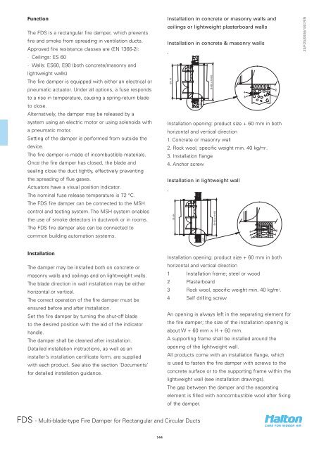
Installation in concrete or masonry walls and<br />
ceilings or lightweight plasterboard walls<br />
Installation in concrete & masonry walls<br />
B x H<br />
~30<br />
B+60 x H+60<br />
Installation opening: product size + 60 mm in both<br />
horizontal and vertical direction<br />
1. Concrete or masonry wall<br />
2. Rock wool, specific weight min. 40 kg/m 3 .<br />
3. Installation flange<br />
4. Anchor screw<br />
Installation in lightweight wall<br />
B x H<br />
~30<br />
B+60 x H+60<br />
20/FDS/0000/1007/EN<br />
Installation<br />
The damper may be installed both on concrete or<br />
masonry walls and ceilings and on lightweight walls.<br />
The blade direction in wall installation may be either<br />
horizontal or vertical.<br />
The correct operation of the fire damper must be<br />
ensured before and after installation.<br />
Set the fire damper by turning the shut-off blade<br />
to the desired position with the aid of the indicator<br />
handle.<br />
The damper shall be cleaned after installation.<br />
Detailed installation instructions, as well as an<br />
installer’s installation certificate form, are supplied<br />
with each product. See also the section ‘Documents’<br />
for detailed installation guidance.<br />
Installation opening: product size + 60 mm in both<br />
horizontal and vertical direction<br />
1 Installation frame; steel or wood<br />
2 Plasterboard<br />
3 Rock wool, specific weight min. 40 kg/m 3 .<br />
4 Self drilling screw<br />
An opening is always left in the separating element for<br />
the fire damper; the size of the installation opening is<br />
about W + 60 mm x H + 60 mm.<br />
A supporting frame shall be installed around the<br />
opening of the lightweight wall.<br />
All products come with an installation flange, which<br />
is used to fasten the fire damper with screws to the<br />
concrete surface or to the supporting frame within the<br />
lightweight wall (see installation drawings).<br />
The gap between the damper and the separating<br />
element is filled with noncombustible wool after fixing<br />
of the damper.<br />
FDS - Multi-blade-type Fire Damper for Rectangular and Circular Ducts<br />
144