Product data sheet - Halton
Product data sheet - Halton
Product data sheet - Halton

You also want an ePaper? Increase the reach of your titles
YUMPU automatically turns print PDFs into web optimized ePapers that Google loves.
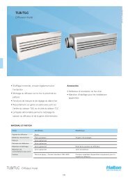
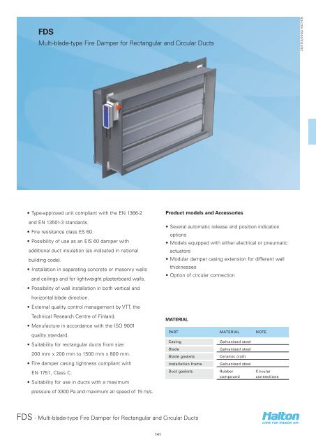
FDS<br />
Multi-blade-type Fire Damper for Rectangular and Circular Ducts<br />
20/FDS/0000/1007/EN<br />
• Type-approved unit compliant with the EN 1366-2<br />
and EN 13501-3 standards.<br />
• Fire resistance class ES 60.<br />
• Possibility of use as an EIS 60 damper with<br />
additional duct insulation (as indicated in national<br />
building code).<br />
• Installation in separating concrete or masonry walls<br />
and ceilings and for lightweight plasterboard walls.<br />
• Possibility of wall installation in both vertical and<br />
horizontal blade direction.<br />
• External quality control management by VTT, the<br />
Technical Research Centre of Finland.<br />
• Manufacture in accordance with the ISO 9001<br />
quality standard.<br />
• Suitability for rectangular ducts from size<br />
200 mm x 200 mm to 1500 mm x 800 mm.<br />
• Fire damper casing tightness compliant with<br />
EN 1751, Class C.<br />
• Suitability for use in ducts with a maximum<br />
pressure of 3300 Pa and maximum air speed of 15 m/s.<br />
<strong>Product</strong> models and Accessories<br />
• Several automatic release and position indication<br />
options<br />
• Models equipped with either electrical or pneumatic<br />
actuators<br />
• Modular damper casing extension for different wall<br />
thicknesses<br />
• Option of circular connection<br />
MATERIAL<br />
PART MATERIAL NOTE<br />
Casing<br />
Blade<br />
Blade gaskets<br />
Installation frame<br />
Duct gaskets<br />
Galvanised steel<br />
Galvanised steel<br />
Ceramic cloth<br />
Galvanised steel<br />
Rubber<br />
compound<br />
Circular<br />
connections<br />
FDS - Multi-blade-type Fire Damper for Rectangular and Circular Ducts<br />
141
DIMENSIONS<br />
W+156<br />
W+130<br />
421<br />
20/FDS/0000/1007/EN<br />
123<br />
W+156<br />
W+130<br />
110<br />
H+4<br />
W+4xH+4<br />
W+4<br />
210 210<br />
1<br />
Rectangular connections<br />
H/W 200 - 800 850 900 950 1000 1050 1100 1150 1200 1250 1300 1350 1400 1450 1500<br />
200 X H H H H H H H H H H H H H H<br />
300 X H H H H H H H H H H H H H H<br />
350 X H H H H H H H H H H H H H H<br />
400 X H H H H H H H H H H H H H H<br />
450 X H H H H H H H H H H H H H H<br />
500 X H H H H H H H H H H H H H H<br />
550 X H H H H H H H H H H H H H H<br />
600 X H H H H H H H H H H H H H H<br />
650 X H H H H H H H H H H H H H H<br />
700 X H H H H H H H H H H H H H H<br />
750 X H H H H H H H H H H H H H H<br />
800 X H H H H H H H H H H H H H H<br />
850 V - - - - - - - - - - - - - -<br />
900 V - - - - - - - - - - - - - -<br />
950 V - - - - - - - - - - - - - -<br />
1000 V - - - - - - - - - - - - - -<br />
1050 V - - - - - - - - - - - - - -<br />
1100 V - - - - - - - - - - - - - -<br />
1150 V - - - - - - - - - - - - - -<br />
1200 V - - - - - - - - - - - - - -<br />
1250 V - - - - - - - - - - - - - -<br />
1300 V - - - - - - - - - - - - - -<br />
1350 V - - - - - - - - - - - - - -<br />
1400 V - - - - - - - - - - - - - -<br />
1450 V - - - - - - - - - - - - - -<br />
1500 V - - - - - - - - - - - - - -<br />
V<br />
H<br />
X<br />
Vertical blade direction only<br />
Horizontal blade direction only<br />
Both horizontal and vertical blade direction allowed<br />
Round connections<br />
W+156<br />
555<br />
W+130 67 421<br />
67<br />
D H W<br />
123<br />
630 600 600<br />
800 800 800<br />
W+156<br />
W+130<br />
110<br />
H+4<br />
D-1<br />
W+4<br />
210 210<br />
1<br />
FDS - Multi-blade-type Fire Damper for Rectangular and Circular Ducts<br />
142
ACCESSORIES AND PRODUCT MODELS<br />
ACCESSORY CODE DESCRIPTION<br />
Mesh on one side<br />
N1<br />
Mesh on both sides<br />
N2<br />
Damper casing extension CE Length 210 mm<br />
Limit switches L2 2 pcs, Bernstein; closed/open position indication<br />
Solenoid valve M1 24 VAC<br />
Solenoid valve M2 230 VAC<br />
20/FDS/0000/1007/EN<br />
Actuators<br />
Pneumatic, AT100 (rotating actuator), P0<br />
Belimo BF 24-T-2 HL, operating voltage AC/DC 24 V<br />
(fuse: 72 ºC, includes limit switch), B1<br />
Belimo BF 230-T-2 HL, operating voltage AC 230 V<br />
(fuse: 72 ºC, includes limit switch), B2<br />
Solenoid operation<br />
The fire damper can be released with an electrical<br />
signal, which is initiated by a smoke detector, limit<br />
switch / pressure switch, or similar. When the circuit<br />
is closed, the operating voltage is switched to the<br />
magnet and the damper closes.<br />
ACCESSORIES<br />
The fire damper can be equipped with a bipolar limit<br />
switch, which indicates the closing of the shut-off<br />
blade. The limit switch has potential-free contacts<br />
(no=normally open and nc=normally closed), which<br />
can be used to control other fire dampers equipped<br />
with an electric release (e.g., triggering an alarm in the<br />
fire suppression system).<br />
The maximum operating voltage and current is 400 V,<br />
10 A.<br />
Option M1 M2<br />
Power supply 24 VDC 230 VAC<br />
Power consumption (design<br />
specification)<br />
15 W 40 VA<br />
Enclosure class (minimum) IP20 IP20<br />
ED 100% 100%<br />
PNEUMATIC ACTUATOR<br />
A fusible link releases and cuts off operating pressure<br />
to the spring-return actuator, allowing springs to<br />
close the damper blades. The fire damper opens<br />
automatically when the fuse has been changed and<br />
the pneumatic air supply is re-established.<br />
ELECTRIC ACTUATOR<br />
A fusible link releases and cuts off operating voltage<br />
to the spring-return motor, allowing the spring to close<br />
the damper blades.<br />
The fire damper always has thermal release operation<br />
(a fuse). Additional release systems available:<br />
FDS - Multi-blade-type Fire Damper for Rectangular and Circular Ducts<br />
143
Function<br />
The FDS is a rectangular fire damper, which prevents<br />
fire and smoke from spreading in ventilation ducts.<br />
Approved fire resistance classes are (EN 1366-2):<br />
· Ceilings: ES 60<br />
· Walls: ES60, E90 (both concrete/masonry and<br />
lightweight walls)<br />
The fire damper is equipped with either an electrical or<br />
pneumatic actuator. Under all options, a fuse responds<br />
to a rise in temperature, causing a spring-return blade<br />
to close.<br />
Alternatively, the damper may be released by a<br />
system using an electric motor or using solenoids with<br />
a pneumatic motor.<br />
Setting of the damper is performed from outside the<br />
device.<br />
The fire damper is made of incombustible materials.<br />
Once the fire damper has closed, the blade and<br />
sealing close the duct tightly, effectively preventing<br />
the spreading of flue gases.<br />
Actuators have a visual position indicator.<br />
The nominal fuse release temperature is 72 °C.<br />
The FDS fire damper can be connected to the MSH<br />
control and testing system. The MSH system enables<br />
the use of smoke detectors in ductwork or in rooms.<br />
The FDS fire damper also can be connected to<br />
common building automation systems.<br />
Installation in concrete or masonry walls and<br />
ceilings or lightweight plasterboard walls<br />
Installation in concrete & masonry walls<br />
B x H<br />
~30<br />
B+60 x H+60<br />
Installation opening: product size + 60 mm in both<br />
horizontal and vertical direction<br />
1. Concrete or masonry wall<br />
2. Rock wool, specific weight min. 40 kg/m 3 .<br />
3. Installation flange<br />
4. Anchor screw<br />
Installation in lightweight wall<br />
B x H<br />
~30<br />
B+60 x H+60<br />
20/FDS/0000/1007/EN<br />
Installation<br />
The damper may be installed both on concrete or<br />
masonry walls and ceilings and on lightweight walls.<br />
The blade direction in wall installation may be either<br />
horizontal or vertical.<br />
The correct operation of the fire damper must be<br />
ensured before and after installation.<br />
Set the fire damper by turning the shut-off blade<br />
to the desired position with the aid of the indicator<br />
handle.<br />
The damper shall be cleaned after installation.<br />
Detailed installation instructions, as well as an<br />
installer’s installation certificate form, are supplied<br />
with each product. See also the section ‘Documents’<br />
for detailed installation guidance.<br />
Installation opening: product size + 60 mm in both<br />
horizontal and vertical direction<br />
1 Installation frame; steel or wood<br />
2 Plasterboard<br />
3 Rock wool, specific weight min. 40 kg/m 3 .<br />
4 Self drilling screw<br />
An opening is always left in the separating element for<br />
the fire damper; the size of the installation opening is<br />
about W + 60 mm x H + 60 mm.<br />
A supporting frame shall be installed around the<br />
opening of the lightweight wall.<br />
All products come with an installation flange, which<br />
is used to fasten the fire damper with screws to the<br />
concrete surface or to the supporting frame within the<br />
lightweight wall (see installation drawings).<br />
The gap between the damper and the separating<br />
element is filled with noncombustible wool after fixing<br />
of the damper.<br />
FDS - Multi-blade-type Fire Damper for Rectangular and Circular Ducts<br />
144
Electric actuator wiring diagram<br />
~ AC 24 V<br />
+ DC 24 V !<br />
Connect via<br />
safety isolating<br />
transformer!<br />
20/FDS/0000/1007/EN<br />
S1 S2 S3<br />
S4 S5 S6<br />
1 2<br />
< 5¡<br />
< 80¡<br />
BF24 HI<br />
Tf1 Tf2 Tf3 BAE72A-S<br />
N L1<br />
230 VAC<br />
S1 S2 S3<br />
S4 S5 S6<br />
1 2<br />
< 5¡<br />
< 80¡<br />
BF230-HI<br />
Tf1 Tf2 Tf3 BAE72A-S<br />
Pneumatic actuator wiring diagram<br />
3<br />
**)<br />
11 13 12<br />
3 3<br />
3<br />
6<br />
6<br />
6<br />
6<br />
6<br />
8 8 10<br />
24 VDC 5<br />
8<br />
230 VAC<br />
6<br />
4 8<br />
6<br />
2<br />
7<br />
3<br />
1<br />
22<br />
14<br />
22<br />
14<br />
9<br />
21<br />
13<br />
21<br />
13<br />
D<br />
E<br />
S<br />
O<br />
L<br />
C<br />
N<br />
E<br />
P<br />
O<br />
**) PNEU. INLET (5–10 BAR) FOR A PLASTIC TUBE Ø<br />
6 MM<br />
1 SPRING-RETURN ACTUATOR<br />
2 QUICK EXHAUST VALVE<br />
3 SILENCER<br />
4 FUSIBLE LINK VALVE<br />
5 OPTION: SOLENOID VALVE<br />
6 MALE CONNECTOR<br />
7 DOUBLE NIPPLE<br />
8 PLASTIC TUBE<br />
9 OPTION: OPEN/CLOSED SWITCHES<br />
10 OPTION: MANUAL VALVE<br />
11 PRESSURE REGULATOR<br />
12 MALE ELBOW<br />
13 SPEED CONTROLLER<br />
NOTE: ADDITIONAL SOLENOID VALVE MAX. 10<br />
METRES FROM FIRE DAMPER<br />
FDS - Multi-blade-type Fire Damper for Rectangular and Circular Ducts<br />
145
Servicing<br />
To ensure proper operation of the fire dampers, they<br />
should be inspected regularly. It is recommended that<br />
the fire damper be connected to automatic control and<br />
testing system MSH (24-V system).<br />
Suggested specifications<br />
Multi-blade-type fire damper FDS for rectangular<br />
and circular ducts. The casing and blades of the fire<br />
damper shall be made of galvanised steel and the<br />
blade gaskets made of incombustible material.<br />
20/FDS/0000/1007/EN<br />
Dampers not connected to an automatic testing<br />
system shall be tested periodically. The minimum<br />
recommended inspection period is one year or<br />
according to building code.<br />
An inspection opening shall be installed in the<br />
proximity of the fire damper as indicated in the<br />
building code (not part of the product).<br />
Upon failure during testing of the fire damper,<br />
maintenance service shall be ordered from an<br />
authorised <strong>Halton</strong> representative, to ensure<br />
appropriate operation of the product.<br />
The fire damper shall be approved for both separating<br />
concrete or masonry walls and ceilings and installation<br />
in lightweight walls according to EN 1366-2 with<br />
ES60(E90w) fire resistance. The fire damper shall be<br />
approved for wall installation in both horizontal and<br />
vertical blade direction.<br />
The fire damper shall be installed on a separating<br />
wall by screws without the need for an additional<br />
installation frame or grouting.<br />
The fire damper shall include a position indicator.<br />
The fire damper shall be equipped with a thermal<br />
fuse. According to specification, the damper shall be<br />
supplied with one of the following release options:<br />
A. Electric signal release by closing circuit (initiated by,<br />
e.g., a smoke detector or a microswitch or pressure<br />
switch); the enclosure class of the electric release<br />
arrangement shall be IP 54 or better.<br />
B. Pneumatic release.<br />
C. Solenoid release as additional option with<br />
pneumatic motor.<br />
FDS - Multi-blade-type Fire Damper for Rectangular and Circular Ducts<br />
146
<strong>Product</strong> code<br />
FDS/S-W-H-D<br />
20/FDS/0000/1007/EN<br />
S = Type of duct connections<br />
R Rectangular connections<br />
C Circular connections<br />
W = Width<br />
S=R: 200, +50, …, 1500<br />
H = Height<br />
S=R: 200, 300, +50, …, 800<br />
D = Connection size<br />
S=C: 630, 800<br />
Specifics and accessories<br />
RE = Release type<br />
B1 BF-24-T-2 HL, fuse: 72 °C<br />
B2 BF-230-T-2 HL, fuse: 72 °C<br />
P0 Pneumatic, rotating AT100<br />
AC = Accessories<br />
CE Casing extension, 210 mm, for structural thickness > 200 mm<br />
L2 Limit switches, 2 pcs, Bernstein, with pneumatic motor<br />
M1 Solenoid valve, 24 VAC, with pneumatic motor<br />
M2 Solenoid valve, 230 VAC, with pneumatic motor<br />
N1 Safety mesh, 1 side, installed in actuator side<br />
N2 Safety mesh, 2 sides<br />
Code example<br />
FDS/R-200-200 , RE=B1, AC=N1<br />
FDS - Multi-blade-type Fire Damper for Rectangular and Circular Ducts<br />
147