GPS Receiver Module LS-40MM LS-40MM
GPS Receiver Module LS-40MM LS-40MM
GPS Receiver Module LS-40MM LS-40MM

You also want an ePaper? Increase the reach of your titles
YUMPU automatically turns print PDFs into web optimized ePapers that Google loves.
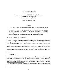
<strong>GPS</strong> <strong>Receiver</strong> <strong>Module</strong><br />
<strong>LS</strong>-<strong>40MM</strong><br />
Features<br />
• 12 parallel channel <strong>GPS</strong> receiver<br />
• 4000 simultaneous time-frequency<br />
search bins<br />
• SBAS (WAAS, EGNOS) support<br />
• High Sensitivity:<br />
• -137dBm acquisition sensitivity<br />
• -145dBm tracking sensitivity<br />
• Fast Acquisition<br />
• < 10 second hot start<br />
• < 45 second cold start<br />
• 5m CEP accuracy<br />
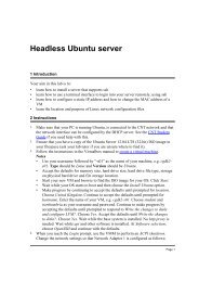
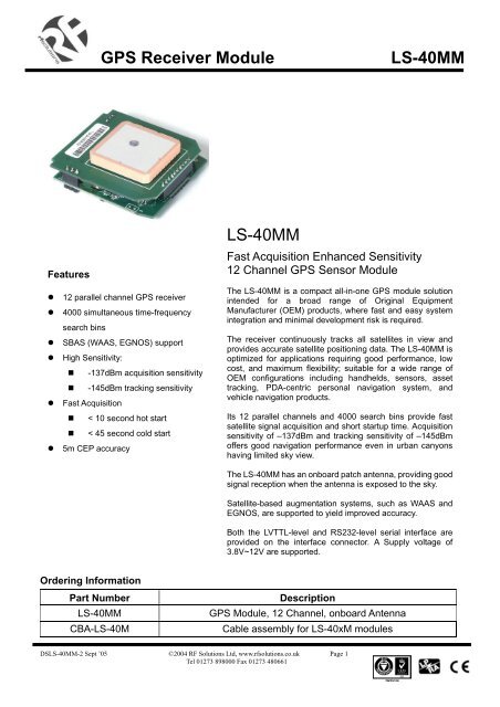
<strong>LS</strong>-<strong>40MM</strong><br />
Fast Acquisition Enhanced Sensitivity<br />
12 Channel <strong>GPS</strong> Sensor <strong>Module</strong><br />
The <strong>LS</strong>-<strong>40MM</strong> is a compact all-in-one <strong>GPS</strong> module solution<br />
intended for a broad range of Original Equipment<br />
Manufacturer (OEM) products, where fast and easy system<br />
integration and minimal development risk is required.<br />
The receiver continuously tracks all satellites in view and<br />
provides accurate satellite positioning data. The <strong>LS</strong>-<strong>40MM</strong> is<br />
optimized for applications requiring good performance, low<br />
cost, and maximum flexibility; suitable for a wide range of<br />
OEM configurations including handhelds, sensors, asset<br />
tracking, PDA-centric personal navigation system, and<br />
vehicle navigation products.<br />
Its 12 parallel channels and 4000 search bins provide fast<br />
satellite signal acquisition and short startup time. Acquisition<br />
sensitivity of –137dBm and tracking sensitivity of –145dBm<br />
offers good navigation performance even in urban canyons<br />
having limited sky view.<br />
The <strong>LS</strong>-<strong>40MM</strong> has an onboard patch antenna, providing good<br />
signal reception when the antenna is exposed to the sky.<br />
Satellite-based augmentation systems, such as WAAS and<br />
EGNOS, are supported to yield improved accuracy.<br />
Both the LVTTL-level and RS232-level serial interface are<br />
provided on the interface connector. A Supply voltage of<br />
3.8V~12V are supported.<br />
Ordering Information<br />
Part Number<br />
<strong>LS</strong>-<strong>40MM</strong><br />
CBA-<strong>LS</strong>-40M<br />
Description<br />
<strong>GPS</strong> <strong>Module</strong>, 12 Channel, onboard Antenna<br />
Cable assembly for <strong>LS</strong>-40xM modules<br />
DS<strong>LS</strong>-<strong>40MM</strong>-2 Sept ’05 ©2004 RF Solutions Ltd, www.rfsolutions.co.uk Page 1<br />
Tel 01273 898000 Fax 01273 480661
<strong>GPS</strong> <strong>Receiver</strong> <strong>Module</strong><br />
<strong>LS</strong>-<strong>40MM</strong><br />
TECHNICAL SPECIFICATIONS<br />
<strong>Receiver</strong> Type<br />
12 parallel channel, L1 C/A code<br />
Accuracy Position 5m CEP<br />
Velocity 0.1m/sec<br />
Startup Time<br />
Reacquisition<br />
Sensitivity<br />
Update Rate<br />
< 10sec hot start<br />
< 35sec warm start<br />
< 45sec cold start<br />
1s<br />
-137dBm acquisition<br />
-145dBm tracking<br />
1Hz<br />
Dynamics 4G (39.2m/sec 2 )<br />
Operational Limits<br />
Serial Interface<br />
Altitude < 18,000m or velocity < 515m/s<br />
(COCOM limit, either may be exceeded but not both)<br />
LVTTL level and RS-232 level<br />
Protocol NMEA-0183 V3.01<br />
GPGGA, GPGLL, GPGSA, GPGSV, GPRMC, GPVTG, GPZDA<br />
4800 baud, 8, N, 1<br />
Datum<br />
Interface Connector<br />
Cable Assembly<br />
Default WGS-84<br />
User definable<br />
1.0mm pitch WTB S/R wafer 87213 SMT R/A type connector<br />
SIL socket to tinned wires, 150mm<br />
Input Voltage 3.8V ~ 12.0V<br />
Current Consumption<br />
Dimension<br />
Weight:<br />
90 ~ 110mA<br />
43mm L x 42mm W x 13mm H<br />
23g<br />
Operating Temperature<br />
-40 o C ~ +85 o C<br />
Humidity 5% ~ 95%<br />
DS<strong>LS</strong>-<strong>40MM</strong>-2 Sept ’05 ©2004 RF Solutions Ltd, www.rfsolutions.co.uk Page 2<br />
Tel 01273 898000 Fax 01273 480661
<strong>GPS</strong> <strong>Receiver</strong> <strong>Module</strong><br />
<strong>LS</strong>-<strong>40MM</strong><br />
Patch Antenna<br />
pin-1<br />
<strong>LS</strong>-<strong>40MM</strong> Lateral View<br />
PINOUT DESCRIPTION<br />
Pin Number Signal Name Description<br />
1 Serial Data Out 1 Asynchronous serial output at LVTTL level, to output NMEA message<br />
2 Serial Data In 1 Asynchronous serial input at LVTTL level, to input command message<br />
3 Serial Data Out 2 Asynchronous serial output at RS-232 level, to output NMEA message<br />
4 Serial Data In 2 Asynchronous serial input at RS-232 level, to input command message<br />
5 Power 3.8V ~ 12.0V DC input<br />
6 Ground Power and signal ground<br />
DS<strong>LS</strong>-<strong>40MM</strong>-2 Sept ’05 ©2004 RF Solutions Ltd, www.rfsolutions.co.uk Page 3<br />
Tel 01273 898000 Fax 01273 480661
<strong>GPS</strong> <strong>Receiver</strong> <strong>Module</strong><br />
<strong>LS</strong>-<strong>40MM</strong><br />
NMEA Messages<br />
The serial interface protocol is based on the National Marine Electronics Association’s NMEA 0183 ASCII<br />
interface specification. This standard is fully define in “NMEA 0183, Version 3.01” The standard may be<br />
obtained from NMEA, www.nmea.org<br />
GGA - <strong>GPS</strong> FIX DATA<br />
Time, position and position-fix related data (number of satellites in use, HDOP, etc.).<br />
Format:<br />
$GPGGA,,,,,,,,,,M,,M,,,*<br />
Example:<br />
$GPGGA,104549.04,2447.2038,N,12100.4990,E,1,06,01.7,00078.8,M,0016.3,M,,*5C<br />
Field Example Description<br />
1 104549.04 UTC time in hhmmss.ss format, 000000.00 ~ 235959.99<br />
2 2447.2038 Latitude in ddmm.mmmm format<br />
Leading zeros transmitted<br />
3 N Latitude hemisphere indicator, ‘N’ = North, ‘S’ = South<br />
4 12100.4990 Longitude in dddmm.mmmm format<br />
Leading zeros transmitted<br />
5 E Longitude hemisphere indicator, 'E' = East, 'W' = West<br />
6 1 Position fix quality indicator<br />
0: position fix unavailable<br />
1: valid position fix, SPS mode<br />
2: valid position fix, differential <strong>GPS</strong> mode<br />
7 06 Number of satellites in use, 00 ~ 12<br />
8 01.7 Horizontal dilution of precision, 00.0 ~ 99.9<br />
9 00078.8 Antenna height above/below mean sea level, -9999.9 ~ 17999.9<br />
10 0016.3 Geoidal height, -999.9 ~ 9999.9<br />
11 Age of D<strong>GPS</strong> data since last valid RTCM transmission in xxx format (seconds)<br />
NULL when D<strong>GPS</strong> not used<br />
12 Differential reference station ID, 0000 ~ 1023<br />
NULL when D<strong>GPS</strong> not used<br />
13 5C Checksum<br />
Note: The checksum field starts with a ‘*’ and consists of 2 characters representing a hex number. The<br />
checksum is the exclusive OR of all characters between ‘$’ and ‘*’.<br />
DS<strong>LS</strong>-<strong>40MM</strong>-2 Sept ’05 ©2004 RF Solutions Ltd, www.rfsolutions.co.uk Page 4<br />
Tel 01273 898000 Fax 01273 480661
<strong>GPS</strong> <strong>Receiver</strong> <strong>Module</strong><br />
<strong>LS</strong>-<strong>40MM</strong><br />
GLL - LATITUDE AND LONGITUDE, WITH TIME OF POSITION FIX AND STATUS<br />
Latitude and longitude of current position, time, and status.<br />
Format:<br />
$GPGLL,,,,,,,*<br />
Example:<br />
$GPGLL,2447.2073,N,12100.5022,E,104548.04,A,A*65<br />
Field Example Description<br />
1 2447.2073 Latitude in ddmm.mmmm format<br />
Leading zeros transmitted<br />
2 N Latitude hemisphere indicator, ‘N’ = North, ‘S’ = South<br />
3 12100.5022 Longitude in dddmm.mmmm format<br />
Leading zeros transmitted<br />
4 E Longitude hemisphere indicator, 'E' = East, 'W' = West<br />
5 104548.04 UTC time in hhmmss.ss format, 000000.00 ~ 235959.99<br />
6 A Status, ‘A’ = valid position, ‘V’ = navigation receiver warning<br />
7 A Mode indicator<br />
‘N’ = Data invalid<br />
‘A’ = Autonomous<br />
‘D’ = Differential<br />
‘E’ = Estimated<br />
8 65 Checksum<br />
GSA - <strong>GPS</strong> DOP AND ACTIVE SATELLITES<br />
<strong>GPS</strong> receiver operating mode, satellites used for navigation, and DOP values.<br />
Format:<br />
$GPGSA,,,,,,,,,,,,,,,,,*<br />
Example:<br />
$GPGSA,A,3,26,21,,,09,17,,,,,,,10.8,02.1,10.6*07<br />
Field Example Description<br />
1 A Mode, ‘M’ = Manual, ‘A’ = Automatic<br />
2 3 Fix type, 1 = not available, 2 = 2D fix, 3 = 3D fix<br />
3 26,21,,,09,17,,,,,, PRN number, 01 to 32, of satellite used in solution, up to 12 transmitted<br />
4 10.8 Position dilution of precision, 00.0 to 99.9<br />
5 02.1 Horizontal dilution of precision, 00.0 to 99.9<br />
6 10.6 Vertical dilution of precision, 00.0 to 99.9<br />
7 07 Checksum<br />
DS<strong>LS</strong>-<strong>40MM</strong>-2 Sept ’05 ©2004 RF Solutions Ltd, www.rfsolutions.co.uk Page 5<br />
Tel 01273 898000 Fax 01273 480661
<strong>GPS</strong> <strong>Receiver</strong> <strong>Module</strong><br />
<strong>LS</strong>-<strong>40MM</strong><br />
GSV - <strong>GPS</strong> SATELLITE IN VIEW<br />
Number of satellites in view, PRN number, elevation angle, azimuth angle, and C/No. Only up to four satellite<br />
details are transmitted per message. Additional satellite in view information is sent in subsequent GSV<br />
messages.<br />
Format:<br />
$GPGSV,,,,,,,,…,,,, *<br />
Example:<br />
$GPGSV,2,1,08,26,50,016,40,09,50,173,39,21,43,316,38,17,41,144,42*7C<br />
$GPGSV,2,2,08,29,38,029,37,10,27,082,32,18,22,309,24,24,09,145,*7B<br />
Field Example Description<br />
1 2 Total number of GSV messages to be transmitted<br />
2 1 Number of current GSV message<br />
3 08 Total number of satellites in view, 00 ~ 12<br />
4 26 Satellite PRN number, <strong>GPS</strong>: 01 ~ 32, SBAS: 33 ~ 64 (33 = PRN120)<br />
5 50 Satellite elevation number, 00 ~ 90 degrees<br />
6 016 Satellite azimuth angle, 000 ~ 359 degrees<br />
7 40 C/No, 00 ~ 99 dB<br />
Null when not tracking<br />
8 7C Checksum<br />
RMC - RECOMMANDED MINIMUM SPECIFIC <strong>GPS</strong>/TRANSIT DATA<br />
Time, date, position, course and speed data.<br />
Format:<br />
$GPRMC,,,,,,,,,,,,*<br />
Example:<br />
$GPRMC,104549.04,A,2447.2038,N,12100.4990,E,016.0,221.0,250304,003.3,W,A*22<br />
Field Example Description<br />
1 104549.04 UTC time in hhmmss.ss format, 000000.00 ~ 235959.99<br />
2 A Status, ‘V’ = navigation receiver warning, ‘A’ = valid position<br />
3 2447.2038 Latitude in dddmm.mmmm format<br />
Leading zeros transmitted<br />
4 N Latitude hemisphere indicator, ‘N’ = North, ‘S’ = South<br />
5 12100.4990 Longitude in dddmm.mmmm format<br />
Leading zeros transmitted<br />
6 E Longitude hemisphere indicator, 'E' = East, 'W' = West<br />
7 016.0 Speed over ground, 000.0 ~ 999.9 knots<br />
8 221.0 Course over ground, 000.0 ~ 359.9 degrees<br />
9 250304 UTC date of position fix, ddmmyy format<br />
10 003.3 Magnetic variation, 000.0 ~ 180.0 degrees<br />
11 W Magnetic variation direction, ‘E’ = East, ‘W’ = West<br />
12 A Mode indicator<br />
‘N’ = Data invalid<br />
‘A’ = Autonomous<br />
‘D’ = Differential<br />
DS<strong>LS</strong>-<strong>40MM</strong>-2 Sept ’05 ©2004 RF Solutions Ltd, www.rfsolutions.co.uk Page 6<br />
Tel 01273 898000 Fax 01273 480661
<strong>GPS</strong> <strong>Receiver</strong> <strong>Module</strong><br />
<strong>LS</strong>-<strong>40MM</strong><br />
‘E’ = Estimated<br />
13 22 Checksum<br />
VTG - COURSE OVER GROUND AND GROUND SPEED<br />
Velocity is given as course over ground (COG) and speed over ground (SOG).<br />
Format:<br />
GPVTG,,T,,M,,N,,K,*<br />
Example:<br />
$GPVTG,221.0,T,224.3,M,016.0,N,0029.6,K,A*1F<br />
Field Example Description<br />
1 221.0 True course over ground, 000.0 ~ 359.9 degrees<br />
2 224.3 Magnetic course over ground, 000.0 ~ 359.9 degrees<br />
3 016.0 Speed over ground, 000.0 ~ 999.9 knots<br />
4 0029.6 Speed over ground, 0000.0 ~ 1800.0 kilometers per hour<br />
5 A Mode indicator<br />
‘N’ = Data invalid<br />
‘A’ = Autonomous<br />
‘D’ = Differential<br />
‘E’ = Estimated<br />
6 1F Checksum<br />
ZDA TIME AND DATE<br />
Format:<br />
$GPZDA,,,,,,*<br />
Example:<br />
$GPZDA,104548.04,25,03,2004,,*6C<br />
Field Example Description<br />
1 104548.04 UTC time in hhmmss.ss format, 000000.00 ~ 235959.99<br />
2 25 UTC time: day (01 ... 31)<br />
3 03 UTC time: month (01 ... 12)<br />
4 2004 UTC time: year (4 digit year)<br />
5 Local zone hour<br />
Not being output by the receiver (NULL)<br />
6 Local zone minutes<br />
Not being output by the receiver (NULL)<br />
7 6C Checksum<br />
Binary Messages<br />
See Binary Message Protocol User’s Guide for detailed descriptions.<br />
DS<strong>LS</strong>-<strong>40MM</strong>-2 Sept ’05 ©2004 RF Solutions Ltd, www.rfsolutions.co.uk Page 7<br />
Tel 01273 898000 Fax 01273 480661
<strong>GPS</strong> <strong>Receiver</strong> <strong>Module</strong><br />
<strong>LS</strong>-<strong>40MM</strong><br />
MECHANICAL CHARACTERISTICS<br />
RF Board<br />
42.0<br />
31.5<br />
5.0 5.5<br />
unit : mm<br />
Digital Board<br />
1.3<br />
0.7<br />
1.4<br />
17.0 5.5<br />
36.1<br />
5.0<br />
6.0<br />
9.5<br />
3.9<br />
5.6<br />
12.7 13.5<br />
12.7<br />
41.1<br />
5.6<br />
25.0<br />
25.0<br />
14.8<br />
11.5<br />
1.5<br />
4.0<br />
35.0<br />
3.0<br />
1.3<br />
41.6<br />
42.6<br />
4.0<br />
0.7<br />
1.0<br />
11.0<br />
2.2<br />
0.2 0.2<br />
1.0<br />
2.0<br />
41.1<br />
RF Solutions Ltd.,<br />
Unit 21, Cliffe Industrial Estate,<br />
South Street, Lewes, E Sussex, BN8 6JL. England<br />
Tel +44 (0)1273 898 000 Fax +44 (0)1273 480 661<br />
Email sales@rfsolutions.co.uk http://www.rfsolutions.co.uk<br />
DS<strong>LS</strong>-<strong>40MM</strong>-2 Sept ’05 ©2004 RF Solutions Ltd, www.rfsolutions.co.uk Page 8<br />
Tel 01273 898000 Fax 01273 480661