Product Manual - Boston Acoustics
Product Manual - Boston Acoustics
Product Manual - Boston Acoustics

You also want an ePaper? Increase the reach of your titles
YUMPU automatically turns print PDFs into web optimized ePapers that Google loves.
GTA<br />
High Performance<br />
Monoblock Amplifiers
Specifications<br />
Introduction<br />
Thank you for choosing <strong>Boston</strong> <strong>Acoustics</strong> and congratulations, you’ve<br />
made the right choice. You’re now equipped for the open road. Your high<br />
performance GTA amplifiers are engineered to perform and built to last.<br />
These products represent the pinnacle of performance and innovation that<br />
<strong>Boston</strong> <strong>Acoustics</strong> is famous for. We hope you enjoy your amplifier and the<br />
road ahead.<br />
Technical Specifications:<br />
GTA-400m<br />
GTA-800m<br />
Rated Power (CEA-2006-A):<br />
@ 2-Ohm (Mono) 400 Watts x 1 800 Watts x 1<br />
@ 4-Ohm (Mono) 250 Watts x 1 500 Watts x 1<br />
Impedance Stability: 2Ω 2Ω<br />
Frequency Response (-3dB): 10Hz–150Hz 10Hz–150Hz<br />
Signal-to-Noise Ratio: >90dB >90dB<br />
(A Weighted)<br />
THD+N: 0.05 0.05<br />
Lowpass Crossover:<br />
Frequency Range: 50Hz - 150Hz 50Hz - 150Hz<br />
Slope (dB Per Octave): 12dB 12dB<br />
Subsonic Filter (Highpass):<br />
Frequency Range: 10Hz - 50Hz 10Hz - 50Hz<br />
Slope (dB Per Octave): 12dB 12dB<br />
Signal Voltage Input Range:<br />
Low Level (RCA) Input: 200mv - 5v 200mv - 5v<br />
Speaker Level Input: 400mv - 10v 400mv - 10v<br />
Fuse Amp Rating (ATC): 40 Amp 2 x 40 Amp<br />
Dimensions:<br />
Width: 10 5 ⁄8” (268mm) 12 1 ⁄2” (318mm)<br />
Height: 2 3 ⁄8” (60mm) 2 3 ⁄8” (60mm)<br />
Depth: 8 3 ⁄8” (211mm) 8 3 ⁄8” (211mm)<br />
Parts List:<br />
GTA-400m<br />
GTA-800m<br />
Owners <strong>Manual</strong>: x 1 x 1<br />
3mm Hex Wrench: x 1 x 1<br />
4mm Hex Wrench: x 1 x 1<br />
Speaker Level Input Cable: x 1 x 1<br />
Mounting Screws: x 4 x 4<br />
Replacement Fuses (ATC): x 1 (40 amp) x 2 (40 amp)<br />
2
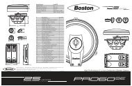
Connections and Controls<br />
GTA-400m<br />
1 2 3 4 5 6 7 8 9 10 11<br />
GTA-800m<br />
Connections / Controls<br />
Speaker Level Input<br />
RCA Input (Left and Right)<br />
Gain (250mv to 5.0v - continuously variable)<br />
Q-Tune “Q” Adjustment (0.707 to 1.6 - cont. variable)<br />
Lowpass Crossover Adjustment (50Hz to 150Hz - cont. variable)<br />
Q-Tune Highpass (Subsonic) Adjustment (10Hz to 50Hz - cont. variable)<br />
GTA-RSL Port (Remote Gain)<br />
Speaker Output Block<br />
Status LED (Blue = Normal / Red = Fault Mode)<br />
Fuse (Replace with same value only, refer to specifications on page 2)<br />
Power Block (12v / Remote / Ground)<br />
13 14 15<br />
Status LED<br />
1 2 3 4 5 6 7 8 9 10 11<br />
The <strong>Boston</strong> Logo will illuminate “Blue” under normal operating conditions.<br />
The LED will illuminate “Red” during start-up and under fault conditions. If the<br />
LED is still red after start-up, please refer to troubleshooting on page 8.<br />
Speaker Level Input Cable<br />
GTA amplifiers offer a dedicated speaker level input for ease installation into<br />
factory systems when an RCA (low level) signal is not available. Wiring code for<br />
the cable is industry standard;<br />
White Solid = Left Positive<br />
Gray Solid = Right Positive<br />
White w/ Black Stripe = Left Negative<br />
Gray w/ Black Stripe = Right Negative<br />
Warning: Do not connect both Speaker Level and RCAs into the amplifier at the<br />
same time as damage to the amplifier may occur.<br />
3
Installation - General<br />
Installation - General<br />
WARNING! Before driving the amplifier mounting screws through any surface,<br />
be sure of what is behind that surface. Check for the gas tank, brake lines, and<br />
any vehicle wiring harness. Never run wires outside or under the vehicle or<br />
where they could become broken or interfere with the safe operation of the<br />
vehicle.<br />
Before You Install<br />
Before you install the unit, disconnect the negative (–) battery cable in the<br />
engine compartment of the vehicle. Doing so will prevent damage to both the<br />
electrical system of the vehicle and the amplifier during installation.<br />
Battery and Charging System<br />
In order for the amplifier to function correctly, the electrical system of the<br />
vehicle should be professionally checked for overall electrical capacity. When<br />
used, the amplifier will increase the demand on the battery and alternator.<br />
Therefore, both should be thoroughly evaluated before installing the amplifier<br />
to ensure they are in normal operating condition and able to handle the<br />
increased demand the amplifier will present to the vehicle’s electrical system.<br />
Wire Routing<br />
Do not run the power wire near any low-level signals or audio cables such as<br />
the RCAs from the head unit. Noise can be introduced into the amplifier when<br />
this occurs. It is helpful to diagram the wire layout first before any installation<br />
is initiated.<br />
Choose the Mounting Location<br />
Plan your installation so that the amplifier is mounted where adequate<br />
ventilation is available. Never mount an amplifier in the engine compartment<br />
of a vehicle!<br />
Passenger and Trunk Compartment Mounting<br />
If the amplifier is mounted under a seat, be sure that there is adequate space<br />
around the amplifier once installed, 1” (25mm) recommended minimum. Do not<br />
allow seat padding or other obstructive material to press down on the amplifier.<br />
When mounting in a trunk, choose a location that will be protected from sliding<br />
cargo or other materials. Mount the amplifier to solid surfaces only. Do not<br />
mount to plastic trim panels. Do not mount the amplifier with Velcro, double-stick<br />
tape, or by wedging into position. Amplifier should be mounted using the screw<br />
mounts in the endpanels and with the provided mounting screws.<br />
Cooling<br />
Position the amplifier so that there is adequate space around the amplifier once<br />
installed, 1” (25mm) recommended minimum.<br />
4
Installation - Wiring<br />
Amplifier Fuses<br />
Although the amplifier has an internal fuse (s), additional fuse protection<br />
should be installed as close as possible to the battery on the positive (+) power<br />
wire going to the amplifier. An inline fuse should be installed at no more than<br />
18" (46cm) on the positive (+) power wire. The rating of the inline fuse should<br />
equal the value of the internal fuse of the amplifier if only the single amplifier is<br />
connected to this wire. If other devices are connected to this wire, the fuse<br />
value should be of sufficient capacity to handle the demand.<br />
Wire Gauge<br />
The amplifier accepts up to 4-gauge (8-gauge on GTA-400m) stripped wire at<br />
the DC power and ground input terminals, and 4-gauge (8-gauge on GTA-400m)<br />
is recommended as a minimum. Wire runs should be kept to the minimum<br />
practical length.<br />
Installation - Wiring<br />
Power 12v and Ground (GND) Connection<br />
Strip approximately 5/8” (16mm) of insulation. The positive (+) power wire is<br />
installed into the amplifier terminal marked “12v”. The negative (–) wire is<br />
installed into the terminal marked “GND”. The ground wire should be as short<br />
as possible and connected directly to the chassis of the vehicle. Make sure that<br />
the chassis connection point is free of rust, grease, dirt, paint, and other<br />
materials that may insulate the ground wire from making proper connection.<br />
Tighten the 12v and GND terminals with the supplied 4mm (3mm on<br />
GTA-400m) hex wrench to secure the wire into the terminals. If the power wire<br />
must be routed through a drilled or existing hole, use a nylon panel grommet<br />
to prevent the insulation from fraying. Failure to do so could lead to an<br />
electrical short if the wire insulation is worn through and the power wire is<br />
shorted to ground.<br />
Remote Input Connection<br />
Connect the REMOTE trigger lead from the head unit to the amplifier using the<br />
3mm hex wrench to tighten the connector on the power block of the amplifier.<br />
(refer to the diagram on page 3).<br />
Speaker Output Connection<br />
Prepare each wire by stripping approximately 5 ⁄8” (16mm) of insulation. The positive<br />
(+) speaker wires are installed into the amplifier terminal marked “SPEAK-<br />
ER OUTPUT” / “+” (refer to the diagram on page 3). The negative (–) speaker<br />
wires are installed into the amplifier terminal marked “SPEAKER OUTPUT” /<br />
“-”. Tighten the “SPEAKER OUTPUT”, “+”, and “-” terminals with the supplied<br />
3mm hex wrench to secure the wires into the terminals. If the speaker wires<br />
must be routed through a drilled or existing hole, use a nylon panel grommet<br />
to prevent fraying the wire insulation. Failure to do so could lead to an electrical<br />
short if the wire insulation is worn through and the speaker wires are shorted<br />
to ground.<br />
WARNING! Subwoofer impedance must not fall below 2-ohms<br />
5
Tuning The Amplifier - Subwoofer(s)<br />
Tuning The Amplifier - Subwoofer(s)<br />
1) Head Unit<br />
The head unit should have all controls such as bass, treble, balance, and fader<br />
set to the flat or centered position. The volume control should be at the<br />
minimum setting. If the head unit has any equalization or bass management<br />
features such as boost, they should be deactivated at this time. Turn head unit<br />
on, and verify that the Blue status LED (logo) is illuminated on the amplifier.<br />
2) Volume<br />
With the chosen musical track playing, turn the head unit volume control up<br />
until the maximum level of undistorted signal is heard from the speakers. For<br />
most head units, this will be at the end of the volume control range.<br />
WARNING! A distorted signal from the head unit sent to the amplifier can<br />
cause speaker failure at higher listening levels.<br />
3) Input Sensitivity Control (Gain)<br />
Turn control (refer to the diagram on page 3) all the way counterclockwise<br />
(minimum position). In this position, the amplifier will be less sensitive to the<br />
input signal from the head unit. Slowly rotate this control clockwise until<br />
maximum undistorted playing level is heard from the subwoofer(s). Listen<br />
closely for faults such as bottoming from the subwoofer(s). If fault is detected,<br />
rotate input sensitivity control counterclockwise until fault is eliminated. At this<br />
point, the maximum undistorted subwoofer playing level has been defined.<br />
6<br />
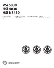
Configuration and C<br />
GTA-400m Amplifier Powering a Subwoofer
Tuning The Amplifier - Subwoofer(s)<br />
4) Lowpass Crossover Control<br />
Experiment with the crossover point settings while the subwoofer is active.<br />
A higher setting will increase the perceived output, and a lower setting will<br />
make the bass response more omnidirectional. Since the Lowpass cannot be<br />
disengaged, set to 15Hz if using an outboard processor or electronic<br />
crossover on the headunit.<br />
5) Q-Tune Control<br />
Once the highpass crossover point has been determined, use the Q-Tune control<br />
(refer to the diagram on page 3) to increase the bass information centered around<br />
the highpass crossover point.<br />
Setting the Q-Tune control is done in conjunction with setting the levels on the<br />
input sensitivity and highpass crossover (subsonic) frequency controls. You may find<br />
while setting the Q-Tune that over-excursion may be detected in the subwoofer (s);<br />
lowering the Q-Tune input sensitivity or raising the highpass crossover point will<br />
eliminate this. Minor adjustments to each setting are required to fine-tune the system.<br />
Setting the Q-Tune is a subtle process. It is recommended that the Q-Tune setting<br />
be left in the 0.7 position and adjusted only after the input sensitivity and<br />
highpass crossover ranges are known. Small adjustments to the Q-Tune setting<br />
are all that are required to fine-tune the system.<br />
6) GTA-RSL Control<br />
The remote level control (GTA-RSL) gives you independent level adjustment of the<br />
subwoofer’s output level beyond the standard system volume control. Please refer<br />
to the RSL’s manual for installation instruction. The GTA-RSL is available separately,<br />
please consult your authorized <strong>Boston</strong> <strong>Acoustics</strong> dealer.<br />
Tuning The Amplifier - Subwoofer(s)<br />
fuse<br />
onnection Diagram:<br />
(80Hz Lowpass, 35Hz Higpass, and Q of 1.2)<br />
7
Amplifier Troubleshooting Guide<br />
Status LEDs on Amplifier not Lit—Head Unit (Source) Turned “ON”<br />
Verify<br />
Remote turn-on wire from source to amplifier has proper voltage<br />
Power (B+) connections at amplifier, terminal blocks, and battery are secure<br />
Ground (GND) connections at amplifier and vehicle chassis are secure<br />
Battery B+ fuse and amplifier fuse are OK<br />
B+ at battery and B+ at amplifier have proper voltage<br />
Status LEDs Lit, no Output from Speakers—Speakers in Normal Operating Condition<br />
Verify<br />
High-level cables from speaker(s) to amplifier are securely connected<br />
RCA or Speaker Level Input from amplifier to source are securely connected<br />
Sensitivity adjustment on amplifier is correctly adjusted<br />
Engine Noise from Speaker(s)<br />
Turn source “OFF” and disconnect RCA cables at amplifier<br />
If noise stops, check equipment and cables leading to amplifier<br />
Verify<br />
RCA cables are of good quality with no breakage to internal shields<br />
RCA cables from source to amplifier are not run alongside power<br />
Amplifier Output Distorted—Music not Recorded with Intentional Distortion<br />
Verify<br />
Source output to amplifier is not distorted<br />
Amplifier input sensitivity is correctly adjusted<br />
Amplifier Shutting Down, RED LED Lit—Amplifier in Thermal Protection Mode<br />
Verify<br />
Amplifier is mounted with adequate space around heatsink<br />
Amplifier is not mounted under carpet<br />
Speakers meet correct impedance for application (mono or stereo hookup)<br />
Amplifier not Turning “ON”, RED LED Lit—Amplifier not Connected to a Shorted Speaker<br />
Verify<br />
Speaker crossover is not defective<br />
High-level cables from speaker to amplifier are not shorted<br />
Amplifier not Turning “ON”, RED LED Lit—Speakers, Crossovers, and Cable OK<br />
Internal fuse needs to be replaced<br />
Verify<br />
Replace fuse with fuse of same value<br />
Amplifier not Turning “ON”, RED LED Lit—Speakers, Crossovers, and Cable OK<br />
Amplifier requires service<br />
If Service Seems Necessary:<br />
First, contact the dealer from whom you purchased the product, or contact us via e-mail at:<br />
USA and Canada: support@bostona.com<br />
Europe: support@bostona.com<br />
Japan: ba_info@dm-holdings.com<br />
Asia/Pacific countries: service@dm-singapore.com<br />
We will promptly advise you of what action to take.<br />
<strong>Boston</strong> <strong>Acoustics</strong>, Inc. 300 Jubilee Drive, Peabody, MA 01960 USA<br />
T: 978.538.5000 F: 978.538.5100 W: bostonacoustics.com/car<br />
<strong>Boston</strong>, B/A ellipse symbol, <strong>Boston</strong> <strong>Acoustics</strong>, and the <strong>Boston</strong> <strong>Acoustics</strong> logo are registered trademarks and Q-Tune is a trademark of <strong>Boston</strong> <strong>Acoustics</strong>, Inc.<br />
Specifications are subject to change without notice. © 2009 <strong>Boston</strong> <strong>Acoustics</strong>, Inc. All rights reserved. Covered by patents issued and/or pending. 142-003821-0