FRIALEN® Safety Fittings for House Service and Supply ... - Friatec
FRIALEN® Safety Fittings for House Service and Supply ... - Friatec
FRIALEN® Safety Fittings for House Service and Supply ... - Friatec
Create successful ePaper yourself
Turn your PDF publications into a flip-book with our unique Google optimized e-Paper software.
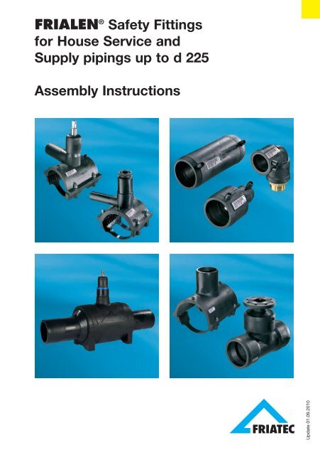
FRIALEN ® <strong>Safety</strong> <strong>Fittings</strong><br />
<strong>for</strong> <strong>House</strong> <strong>Service</strong> <strong>and</strong><br />
<strong>Supply</strong> pipings up to d 225<br />
Assembly Instructions<br />
Update 01.09.2010
Update 01.09.2010<br />
Contents Page<br />
FRIALEN ® <strong>Safety</strong> <strong>Fittings</strong>:<br />
2<br />
1. <strong>Safety</strong> 3<br />
2. Areas of application 3<br />
3. Regulations <strong>and</strong> processing instructions 4<br />
4. Couplers, Elbows, T-Pieces d 20 - d 225 6<br />
5. Pressure Tapping Tees, Pressure Tapping Valves 14<br />
6. Valve Tapping Saddles 20<br />
7. Shut-off Saddles 21<br />
8. Spigot Saddles 22<br />
9. Rein<strong>for</strong>cement <strong>and</strong> repair saddles 22<br />
10. FRIALOC ® PE shut-off valve 23<br />
11. Ball Valves 26<br />
12. Tapping Ball Valves 27<br />
13. Transition <strong>Fittings</strong> 27<br />
14. Repair Sleeves <strong>for</strong> pipes d 32 – d 63, SDR 11 29<br />
15. Updates of assembly instructions 30<br />
For further in<strong>for</strong>mation on the processing of FRIALEN ® <strong>Safety</strong> <strong>Fittings</strong>,<br />
please contact:<br />
FRIATEC Aktiengesellschaft<br />
Technical Plastics Division<br />
P.O.B. 710261 · D-68222 Mannheim<br />
Phone +49 621 486-1431<br />
Fax +49 621 479196<br />
Internet: www.frialen.com<br />
Email: info-frialen@friatec.de<br />
Hotline +49 621 486-1486
1. <strong>Safety</strong><br />
1.1 <strong>Safety</strong> advice <strong>and</strong> tips<br />
The following warning symbols are used in these assembly instructions:<br />
DANGER!<br />
Describes impending danger!<br />
Non-observance of this warning may lead to serious damages to health <strong>and</strong><br />
objects.<br />
WARNING!<br />
Describes a dangerous situation!<br />
Non-observance of this warning may cause minor injuries or damage to<br />
objects.<br />
IMPORTANT!<br />
Describes advice <strong>and</strong> other useful in<strong>for</strong>mation!<br />
2. Areas of application<br />
FRIALEN ® <strong>Safety</strong> <strong>Fittings</strong> are used <strong>for</strong> weld joints at pressure pipes made of<br />
polyethylene in the dimensions SDR 17.6 to SDR 11 <strong>for</strong> use in gas <strong>and</strong> water<br />
supply, pressure drainage, industry <strong>and</strong> l<strong>and</strong>fill construction.<br />
FRIALEN ® <strong>Safety</strong> <strong>Fittings</strong> can be fused with pipes of the dimensions<br />
SDR17.6 to SDR11, given a minimum wall thickness of at least ≥ 3.0 mm.<br />
Other fusion ranges, e.g. SDR7.4, are listed in the technical documentation<br />
<strong>and</strong> are directly identified on the product.<br />
Please contact us <strong>for</strong> the processing of pipes with deviating wall thickness<br />
or SDR.<br />
When operating with other media than drinking water <strong>and</strong> natural gas, please<br />
contact our application engineering department.<br />
IMPORTANT!<br />
The in<strong>for</strong>mation <strong>and</strong> processing instructions mentioned on the fitting or<br />
enclosed shall apply predominantly.<br />
01.09.2010<br />
3 Update
Update 01.09.2010<br />
3. Regulations <strong>and</strong> processing instructions<br />
For detailed <strong>and</strong> up-to-date in<strong>for</strong>mation on FRIALEN ® <strong>Safety</strong> <strong>Fittings</strong>, please<br />
see the technical datasheets available on the Internet (www.frialen.com).<br />
Please observe the guidelines of the DVGW regulations, of DVS, BGR 500<br />
(VBG 50), EN 1555, EN 12201, EN 13244, accident prevention regulations<br />
<strong>and</strong> the relevant country-specific regulations.<br />
DANGER!<br />
The described sequence of the processes is absolutely to be adhered<br />
to.<br />
FRIALEN ® <strong>Safety</strong> <strong>Fittings</strong> can be used with pipes made of PE 100,<br />
PE 80, PE 63, PE 50 according to DIN 8074/75, EN 1555-2, EN 12201-2,<br />
EN 13244-2, ISO 4437 <strong>and</strong> ISO 4427, PE-Xa according to DIN 16892/93<br />
(only up to pipe diameter 63mm; other pipe diameters on request), LDPE<br />
according to DIN 8072/73.<br />
For PE pipes, a fusion flow rate MFR 190/5 in the range of 0.2 – 1.7g/10 min.<br />
applies.<br />
We recommend using pipes with a limited dimension tolerance range,<br />
tolerance class B.<br />
LDPE pipes can be fused at ambient temperatures > 0°C.<br />
FRIALEN ® <strong>Safety</strong> <strong>Fittings</strong> consist of PE 100 <strong>and</strong> meet the requirements<br />
accord ing to DIN 16963-5, -7, EN 1555-3, EN 12201-3, EN 13244-3, ISO 4427-<br />
3, ISO 8085-3 as well as the DVGW test bases. FRIALEN ® <strong>Safety</strong> <strong>Fittings</strong> can<br />
be fused with FRIAMAT ® Electrofusion Units at ambient temperatures between<br />
- 10°C <strong>and</strong> + 45°C.<br />
For material transition joints, the material- or system-specific st<strong>and</strong>ards <strong>and</strong><br />
installation guidelines apply in addition.<br />
WARNING!<br />
Fusion with other pipe materials such as e.g. PP, PVC etc. is not<br />
possible.<br />
WARNING!<br />
During processing, pipes <strong>and</strong> fittings should have a balanced temperature<br />
level in the permissible range of application between -10°C <strong>and</strong> +45°C.<br />
4
IMPORTANT!<br />
FRIALEN ® <strong>Safety</strong> <strong>Fittings</strong> are identified by a batch marking.<br />
This reads from left to right: Example:<br />
Production week (KW) (stamp 1+2)<br />
Production year (stamp 2)<br />
Material identification letter (stamp 3)<br />
KW 14/01/E<br />
The FRIALEN ® Fitting can be stored <strong>and</strong> processed <strong>for</strong> a long time, provided<br />
the general storage specifications are adhered to. When properly stored (in<br />
closed rooms or containers (boxes) <strong>and</strong>/or not exposed to UV radiation as<br />
well as effects of weather like humidity etc.), a storage <strong>and</strong> processing period<br />
of more than 4 years can be assumed.<br />
WARNING!<br />
Improperly stored component parts may not be processed because this<br />
may result in leaking fusion joints.<br />
Traceability<br />
An automatic component traceability is possible when using e.g. traceabilitycapable<br />
FRIAMAT ® Electrofusion Units with a special barcode (see Fig. 9)<br />
which contains the specific data of the fitting, e.g. manufacturer, dimension,<br />
material, batch. These data on component traceability can be electronically<br />
archived together with the fusion process data.<br />
IMPORTANT!<br />
Manual electrofusion units (without barcode reader), e.g. FWS 225, are<br />
no longer state-of-the art. Processing of FRIALEN ® <strong>Safety</strong> <strong>Fittings</strong> with<br />
these units is thus no longer possible.<br />
3.1 Pressure load-bearing capability<br />
The pressure load-bearing capability of FRIALEN ® <strong>Safety</strong> <strong>Fittings</strong> made of<br />
PE 100 is determined by the identification SDR.<br />
Pipe outer diameter ø d<br />
SDR =<br />
Pipe wall thickness s<br />
01.09.2010<br />
5 Update
Update 01.09.2010<br />
The design factor C (calculation coefficient <strong>for</strong> PE components) depends on<br />
the area of application <strong>and</strong> the specifications (min. 1.25).<br />
6<br />
Fitting material: PE 100<br />
(FRIALEN<br />
Water Gas<br />
® st<strong>and</strong>ard)<br />
SDR Stage maximum operating pressure maximum operating pressure<br />
in bar <strong>for</strong> C = 1.25 in bar <strong>for</strong> C = 2<br />
17 10 5<br />
11 16 10<br />
7,4 25 -<br />
The parts are identified <strong>and</strong> usable with regard to their load-bearing capa bility<br />
according to the above table.<br />
For pressure classifications deviating from this identification, e.g. because of<br />
function-related limitations <strong>for</strong> FRIASTOPP ® , the data on the fitting or in the<br />
technical data sheets are to be observed.<br />
DANGER!<br />
Fusion with escaping media is not permissible.<br />
4. Couplers, Elbows, T-Pieces d 20 - d 225<br />
4.1 Cutting to length of pipes<br />
Cut off the pipe in a right angle to the<br />
pipe axis (see Fig. 1). A suitable tool<br />
is a PE pipe cutter or a saw with<br />
toothing suitable <strong>for</strong> plastics.<br />
DANGER!<br />
A non-rectangular pipe cutting<br />
may cause the heating coil partially<br />
not being covered by the pipe<br />
which may result in overheating,<br />
uncontrolled melt <strong>for</strong>mation or<br />
self-ignition (see Fig. 2).<br />
Fig. 1<br />
Fig. 2
4.2 Measure fusion zone, mark<br />
with a FRIALEN ® marker<br />
<strong>and</strong> remove oxide layer<br />
Fusion zone:<br />
For fittings in general the insertion<br />
depth, i.e. the distance between the<br />
coupler edge <strong>and</strong> the internal stop.<br />
For slide over couplers, the distance<br />
between the coupler edge<br />
<strong>and</strong> the centre of the coupler.<br />
At first, remove contaminations from<br />
the pipe. A processing allowance of<br />
approx. +5mm in addition of the<br />
insertion depth provides proof after<br />
fusion that the oxide layer has been<br />
removed properly. Using a manual<br />
scraper or FRIATOOLS ® Scraper<br />
tools FWSG (see Fig. 3-5), the oxide<br />
layer, which <strong>for</strong>med during on the<br />
surface of HDPE pipes <strong>and</strong> spigot<br />
fittings during storage, has to be<br />
removed completely directly be<strong>for</strong>e<br />
the assembly.<br />
Pipe spigots, e.g. at fittings DAA,<br />
DAV…, ball valves KH, KHP or<br />
thread connecting adapters UAN/<br />
UAM are to be prepared analogue to<br />
the processing specifications <strong>for</strong><br />
pipes.<br />
Rotational scraper tools are prescribed<br />
pursuant to DVS2207-1,<br />
Supplement 1, <strong>for</strong> the preparation of<br />
PE-X pipes.<br />
An equal <strong>and</strong> seamless scraping is<br />
achieved by using FWSG scraper<br />
tools.<br />
FWSG 63 d 20 - d 63<br />
FWSG 225 d 75 - d 225<br />
FWSG SE d 63 - d 315*<br />
Fig. 3<br />
Fig. 4<br />
Fig. 5<br />
*Dimension-dependent units <strong>for</strong> the processing of pipe ends <strong>and</strong> saddle<br />
fusion areas (Fig. 5)<br />
01.09.2010<br />
7 Update
Update 01.09.2010<br />
The scraping result is to be verified.<br />
WARNING!<br />
If the oxide layer is not removed completely, inhomogeneous, leaking<br />
fusion joints may result.<br />
A one-time, complete removal is sufficient (min. 0.15 mm). Damages to the<br />
pipe surface as e.g. axial grooves or scratches may not be located within the<br />
fusion zone.<br />
WARNING!<br />
An excessive swarf removal may result in an excessively large annular<br />
gap which either cannot or only insufficiently closed by fusion.<br />
Please thus regularly check the condition of the blade at the manual<br />
scraper <strong>and</strong> the wear of the scraper blade at the scraper tool. Worn<br />
blades must be replaced (see FRIALEN ® Info No. 1).<br />
8<br />
Scraper tool Desired swarf thickness (mm) Wear limit (mm)<br />
FWSG 63 0.15 - 0.25 > 0.3<br />
FWSG 225 0.25 - 0.35 > 0.4<br />
FWSG SE ≤ d63 0.15 – 0.25 < 0.15 / > 0.3<br />
FWSG SE > d63 – d225 0.25 – 0.35 < 0.15 / > 0.4<br />
Please note that the indicated wearing margin applies to FRIALEN ®<br />
<strong>Safety</strong> <strong>Fittings</strong>. Where appropriate please observe manufacturers’<br />
indications.<br />
Filing or s<strong>and</strong>ing are not permitted because contaminations are introduced.<br />
For a control of the complete surface removal over the entire surface, we<br />
recommend to apply marking (control) lines (see Fig. 3). If during scraping of<br />
the surface non-scraped areas occur at some points (e.g. in case of bundled<br />
coil goods or oval pipes), these areas are to be reworked. The processed zone<br />
is to be protected against dirt, soap, grease, subsequently flowing water <strong>and</strong><br />
unfavourable effects of weather (e.g. moisture, frost <strong>for</strong>mation). Do not touch<br />
the fusion zone again after scraping.
WARNING!<br />
FRIALEN ® <strong>Safety</strong> <strong>Fittings</strong> with integrated heating coils guarantee optimal<br />
heat transfer through their exposed heating coils <strong>and</strong> may thus not<br />
be scraped at the inside of the fitting.<br />
4.3 External <strong>and</strong> internal chamfering of the cutting edge<br />
For this purpose, the manual scraper is a suitable tool. Remove swarves<br />
from within the pipe.<br />
4.4 Restoration of irregular /<br />
oval pipes<br />
Pipes, in particular bundled coils <strong>and</strong><br />
drums, may loose their roundness<br />
during storage. If the pipe out-ofroundness<br />
in the fusion zone area<br />
exceeds 1.5% of d (outer diameter)<br />
or is > 3.0 mm, these pipes must be<br />
rounded in the fusion zone area.<br />
Please use rounding clamps <strong>for</strong> this<br />
purpose which are installed at the<br />
end of the fusion zone (see Fig. 6).<br />
4.5 Cleaning<br />
The surfaces of the pipes to be fused<br />
<strong>and</strong> the interior surfaces of the<br />
FRIALEN ® <strong>Safety</strong> <strong>Fittings</strong> must be<br />
absolutely clean, dry <strong>and</strong> free from<br />
any grease. These areas are to be<br />
cleaned with a suitable cleaning<br />
agent <strong>and</strong> exclusively with absorbent,<br />
lint-free <strong>and</strong> non-dyed paper<br />
directly be<strong>for</strong>e the assembly <strong>and</strong> after<br />
scraping (see Fig. 7).<br />
Fig. 6<br />
Fig. 7<br />
We recommend PE cleaning agents which meet the requirements of the test<br />
basis DVGW-VP 603, e.g. AHK cleaning agents.<br />
The amount of the PE cleaning agent is to be chosen such that the paper is<br />
slightly wetted. Skin contact is to be avoided. Please observe the safety notes<br />
of the manufacturer of the PE cleaning agent.<br />
When cleaning, ensure that no contaminations from the unscraped pipe<br />
surface are introduced into the fusion zone.<br />
01.09.2010<br />
9 Update
Update 01.09.2010<br />
WARNING!<br />
When using alcoholic cleaning agents, the alcohol percentage must be<br />
at least 99.8% according to DVGW-VP 603.<br />
The cleaning agent must be completely evaporated be<strong>for</strong>e starting the<br />
fusion process.<br />
Subsequently, re-apply marking line <strong>for</strong> the fusion zone width with the<br />
FRIALEN ® marker because this line was removed during scraping <strong>and</strong><br />
cleaning. The joint surfaces must be clean <strong>and</strong> dry be<strong>for</strong>e installing the<br />
fitting. The cleaned fusion zone should not be touched with bare h<strong>and</strong>s.<br />
Moisture in the area of the joint area, e.g. because of dew or frost, is to be<br />
removed using suitable aids.<br />
The fusion fitting is to be removed from the packaging only directly be<strong>for</strong>e<br />
the planned processing. The packaging protects the fittings against external<br />
influences during transport <strong>and</strong> storage.<br />
4.6 Positioning of insertion or pipe ends into the fitting<br />
When connecting FRIALEN ® <strong>Safety</strong> <strong>Fittings</strong> <strong>and</strong> pipes, it is to be ensured<br />
that the contact sockets <strong>for</strong> connecting the fusion plug are accessible. Do<br />
not jam when connecting. The FRIALEN ® <strong>Safety</strong> <strong>Fittings</strong> should be slipped<br />
on without using <strong>for</strong>ce. The processed insertion end must be inserted into<br />
the fitting up to the mark. If needed, rounding clamps (see Fig. 6) are to be<br />
used.<br />
Repeated scraping may not be per<strong>for</strong>med to remedy installation problems<br />
due to out-of-roundness!<br />
If the fitting cannot be slipped on without using <strong>for</strong>ce despite the above<br />
described procedure, a repeated scraping is permitted.<br />
A simple control of the high points is possible by installing the coupler <strong>and</strong><br />
evaluating the annular gap.<br />
4.7 Ensuring a tension-free assembly of the components<br />
All joints prepared <strong>for</strong> fusion must be tension-free. Pipes may not be positioned<br />
in the FRIALEN ® <strong>Safety</strong> Fitting under bending stress or self-load.<br />
After the installation on the pipe ends, it must still be possible to move the<br />
couplers by h<strong>and</strong>.<br />
If required, the piping or the fitting is to be supported or suitable fixing<br />
facilities are to be used. The tension-free fixing of the joint is to be maintained<br />
until the cooling time stated on the barcode <strong>and</strong> in the table (see Item 4.9) is<br />
reached.<br />
10
Be<strong>for</strong>e starting the fusion process, check again based on the markings<br />
whether the position of the pipe insertion end in the FRIALEN ® <strong>Safety</strong> Fitting<br />
has shifted (correct, if required).<br />
WARNING!<br />
A non-tension-free or shifted joint<br />
may result in an impermissible<br />
melt flow <strong>and</strong> a defective joint<br />
during fusion (see Fig. 8).<br />
4.8 Carrying out fusion<br />
WARNING!<br />
Only use fusion units which have been approved by the manufacturer<br />
with regard to their function <strong>for</strong> the processing of FRIALEN ® <strong>Safety</strong><br />
<strong>Fittings</strong>. See DVS 2207-1.<br />
The fusion parameters are contained<br />
in the main barcode affixed to the<br />
FRIALEN ® <strong>Safety</strong> Fitting. When<br />
using fully automatic fusion units<br />
(e.g. FRIAMAT ® ), the parameters are<br />
entered into the fusion unit using the<br />
reader.<br />
Fig. 8<br />
The subordinated barcode contains Fig. 9<br />
the data <strong>for</strong> component traceability<br />
(see in<strong>for</strong>mation 2). This barcode is only to be read if the component traceability<br />
function is to be used. This requires suitable fusion units.<br />
The fusable pipe series are listed in the SDR labelling on the label.<br />
The fusion units automatically monitor the fusion process <strong>and</strong> control the<br />
supplied energy in determined limits.<br />
01.09.2010<br />
11 Update
Update 01.09.2010<br />
INFORMATION:<br />
The fusion parameters are encoded<br />
on the barcode label in the<br />
<strong>for</strong>m of a 24-digit figure (top), the<br />
data <strong>for</strong> component traceability in<br />
the <strong>for</strong>m of a 26-digit column of<br />
numbers (bottom), <strong>and</strong> can also<br />
be entered manually into the<br />
FRIAMAT ® fusion unit using the<br />
emergency entry mode.<br />
For fittings with separate coils (see<br />
Fig. 10), each fitting side is to be<br />
fused separately.<br />
For fittings with continuous coil,<br />
both fitting sides are to be fused<br />
simultaneously (see Fig. 11).<br />
For FRIALEN ® <strong>Safety</strong> <strong>Fittings</strong> equipped<br />
with a fusion indicator, the latter<br />
only indicates to the per<strong>for</strong>med<br />
fusion process. The proper fusion<br />
process is, however, only indicated<br />
by the fusion unit!<br />
After reading of the barcode, the<br />
fitting data are to be compared with<br />
the data shown on the unit’s display.<br />
If they are identical, start fusion.<br />
Please observe the operating instruction<br />
of the FRIAMAT ® fusion<br />
unit.<br />
Avoid stress on the connecting spot.<br />
Fig. 12<br />
WARNING!<br />
Keep a distance of one meter to the fusion site during the fusion process<br />
<strong>for</strong> general safety reasons.<br />
12<br />
Fig. 10<br />
Fig. 11
The obtained actual fusion time is to be compared with the target fusion<br />
time on the unit <strong>and</strong> to be noted on the pipe or the FRIALEN ® <strong>Safety</strong> Fitting<br />
(see Fig. 12).<br />
With this identification it is ensured that no fusion point is overlooked.<br />
In case of doubt, a fusion can be repeated. But the joint surfaces must be<br />
cooled down to ambient temperature be<strong>for</strong>e each renewed fusion. Please<br />
contact <strong>for</strong> this purpose your local FRIALEN ® sales engineer by phone or the<br />
FRIALEN ® Hotline.<br />
4.9 Cooling times.<br />
The cooling time is<br />
a) the time which is required to cool down the component to the temperature<br />
which facilitates the movement of the joint. This time is also listed on the<br />
barcode <strong>and</strong> is identified by CT.<br />
b) the time which is required to cool down the component to the temperature<br />
which facilitates the application of the full test or operating pressure. This<br />
is classified into pressure volumes of up to 8 bar <strong>and</strong> > 8 bar.<br />
Diameter Cooling time in minutes <strong>for</strong> FRIALEN ®<br />
in mm couplers <strong>and</strong> fittings<br />
CT Up to pressurising Up to pressurising<br />
until the at up to 8 bar at > 8 bar<br />
joint may be<br />
moved<br />
20 – 32 5 8 10<br />
40 – 63 7 15 25<br />
75 – 110 10 30 40<br />
125 – 140 15 35 45<br />
160 – 225 20 60 75<br />
INFORMATION:<br />
A piping may only be commissioned after successful pressure test (see<br />
EN 805, EN 12007 <strong>and</strong> DVGW G 469, W 400).<br />
The guidelines of the DVGW leaflets <strong>for</strong> pressure tests, the European<br />
st<strong>and</strong>ards or the country-specific regulations are to be observed.<br />
01.09.2010<br />
13 Update
Update 01.09.2010<br />
5. Pressure Tapping Tees, Pressure Tapping Valves<br />
FRIALEN ® Pressure Tapping Tees <strong>and</strong> Pressure Tapping Valves are suitable<br />
to be used as branches <strong>for</strong> unpressurised <strong>and</strong> pressurised pipings.<br />
WARNING!<br />
Saddle components d 40 – d 63 cannot be processed with SDR 17<br />
HD-PE pipes.<br />
For tapping-technical reasons, FRIALEN ® Pressure Tapping Tees can in<br />
general not be processed with SDR 7.4 pipes, <strong>and</strong> pressure tapping<br />
valves can in general not be processed with SDR 7.4 <strong>and</strong> SDR 9 pipes.<br />
Please read our fitting data sheets<br />
or ask the FRIALEN ® application<br />
engineer.<br />
5.1 Measuring of fusion zone of<br />
the pipes (<strong>and</strong> the lateral<br />
outlet spigot), marking <strong>and</strong><br />
removing oxide layer<br />
At first, remove contaminations from<br />
the pipe.<br />
Fusion zone: is the pipe surface<br />
covered by the upper part (see Fig.<br />
13); in case of lateral outlets the inser<br />
tion depth at the smooth fusion<br />
end. Using a FRIATOOLS ® Scraper<br />
tool (see Fig. 14), the oxide layer,<br />
which <strong>for</strong>med during on the surface<br />
during storage, has to be removed<br />
com pletely from the area of the<br />
fusion zone directly be<strong>for</strong>e the assembly.<br />
A processing allowance of several Fig. 14<br />
millimetres in addition to the covered<br />
area provides proof after fusion that the oxide layer has been properly removed<br />
from the pipe.<br />
14<br />
Fig. 13
WARNING!<br />
If the oxide layer is not removed completely, leaking fusion joints may<br />
result.<br />
Worn blades of the scraper tool <strong>and</strong> manual scraper must be replaced.<br />
A one-time, complete removal is sufficient (min. 0.15mm). A uni<strong>for</strong>m surface<br />
without flattening <strong>and</strong> material grates at the pipe diameter should be the result.<br />
WARNING!<br />
Filing or s<strong>and</strong>ing of the pipe is not permitted because contaminations<br />
are introduced.<br />
For a control of the complete surface removal over the entire surface, we<br />
recommend to apply marking (control) lines. If during scraping of the surface<br />
non-scraped areas occur at some points, these areas are to be reworked.<br />
The processed zone is to be protected against dirt, soap, grease, subsequently<br />
flowing water <strong>and</strong> unfavourable effects of weather (e.g. moisture,<br />
frost <strong>for</strong>mation).<br />
5.2 Cleaning<br />
The surfaces of the pipes to be fused <strong>and</strong> the interior surfaces of the FRIALEN ®<br />
<strong>Safety</strong> <strong>Fittings</strong> must be absolutely clean, dry <strong>and</strong> free from any grease. These<br />
areas are to be cleaned with a suitable cleaning agent <strong>and</strong> exclusively<br />
with absorbent, lint-free <strong>and</strong> non-dyed paper directly be<strong>for</strong>e the assembly<br />
<strong>and</strong> after scraping. We recommend PE cleaning agents which meet the requirements<br />
of the test basis DVGW-VP 603, e.g. AHK cleaning agents.<br />
When cleaning, ensure that no contaminations from the unscraped pipe<br />
surface are introduced into the fusion zone.<br />
WARNING!<br />
When using alcoholic cleaning agents, the alcohol percentage must be<br />
at least 99.8% according to DVGW-VP 603.<br />
01.09.2010<br />
15 Update
Update 01.09.2010<br />
The cleaning agent must be completely evaporated be<strong>for</strong>e starting the<br />
fusion process.<br />
Subsequently, re-apply marking line <strong>for</strong> the fusion zone width with the<br />
FRIALEN ® marker because this line was removed during scraping <strong>and</strong><br />
cleaning. The joint surfaces must be clean <strong>and</strong> dry be<strong>for</strong>e installing the<br />
fitting. The cleaned fusion zone should not be touched with bare h<strong>and</strong>s.<br />
Moisture in the area of the joint area, e.g. because of dew or frost, is to be<br />
removed using suitable aids.<br />
The fusion fitting is to be removed from the packaging only directly be<strong>for</strong>e the<br />
planned processing. The packaging protects the fittings against external<br />
influences during transport <strong>and</strong> storage.<br />
5.3 Assembly<br />
- Loosen pre-mounted screws on<br />
one side.<br />
- Open upper <strong>and</strong> lower part; still<br />
screwed side serves as hinge.<br />
- Place onto processed pipe area.<br />
- Tighten all four screws equally<br />
cross-wise up to the stop using<br />
an Allen wrench (see Fig. 15).<br />
16<br />
Allen wrench Fitting<br />
SW 5 up to d 75<br />
SW 6 from d 90<br />
Fig. 15<br />
Bottom parts are a component part of the fittings <strong>and</strong> serve the application of<br />
the joining pressure.<br />
WARNING!<br />
For pressure tapping tees <strong>and</strong> pressure tapping valves, the factory drill<br />
setting may not be changed be<strong>for</strong>e starting the fusion process.<br />
5.4 Carrying out of fusion<br />
When fusing Pressure Tapping Tees <strong>and</strong> Valves to media-carrying pipings,<br />
the following operating pressures may not be exceeded until the pipe has<br />
cooled down completely:
Pipe material PE 80 PE 100<br />
SDR 17 11 17 11<br />
Maximum permissible operating pressure in bar<br />
Gas pipe 2 5 5 10<br />
Water pipe 8 12,5 10 16<br />
WARNING!<br />
Only use fusion units which have been approved by the manufacturer<br />
with regard to their function <strong>for</strong> the processing of FRIALEN ® <strong>Safety</strong><br />
<strong>Fittings</strong>. See DVS 2207-1.<br />
The fusion parameters are contained in the main barcode affixed to the<br />
FRIALEN ® <strong>Safety</strong> Fitting. When using fully automatic fusion units (e.g.<br />
FRIAMAT ® ), the parameters are entered into the fusion unit using the reader.<br />
After reading of the barcode, the fitting data are to be compared with the<br />
data shown on the unit’s display. If they are identical, start fusion. Please<br />
observe the operating instruction of the FRIAMAT ® fusion unit.<br />
A pressure test of the branch line can be per<strong>for</strong>med be<strong>for</strong>e tapping the<br />
main line.<br />
The fusion units automatically monitor the fusion process <strong>and</strong> control the<br />
supplied voltage in determined limits.<br />
The indicator only indicates to the per<strong>for</strong>med fusion process. The proper<br />
fusion process is, however, only indicated by the fusion unit!<br />
WARNING!<br />
Keep a distance of one meter to the fusion site during the fusion process<br />
<strong>for</strong> general safety reasons.<br />
The obtained ACTUAL fusion time is to be compared with the target fusion<br />
time on the unit <strong>and</strong> to be noted on the pipe or the FRIALEN ® <strong>Safety</strong> <strong>Fittings</strong>.<br />
With this identification it is ensured that no fusion point is overlooked.<br />
01.09.2010<br />
17 Update
Update 01.09.2010<br />
5.5 Tapping <strong>and</strong> application of the test <strong>and</strong> operating pressure<br />
The following waiting times are to be observed:<br />
18<br />
Diameter Cooling time in minutes <strong>for</strong> FRIALEN ®<br />
in mm Saddle fittings<br />
Up to pressurisation CT<br />
via outlet Up to<br />
tapping<br />
40 – 63 15 20<br />
75 – 125 20 30<br />
140 – 160 30 45<br />
180 – 225 50 60<br />
The cooling time CT stated on the components corresponds to the cooling<br />
time until tapping.<br />
WARNING!<br />
If the waiting times are not observed, leaking fusion joints may result.<br />
The general installation instructions must be observed be<strong>for</strong>e tapping.<br />
5.6 Tapping of Pressure<br />
Tapping Tees<br />
Remove blanking plug. Turn the drill<br />
down up to the lower stop using the<br />
matching FRIALEN ® activating key<br />
(see Fig. 16).<br />
d SW<br />
40 10<br />
50 to 75 17<br />
DAA d1 63 / d2 63 19<br />
≥ 90 19<br />
Fig. 16<br />
Turn the drill backwards up to the upper stop.<br />
Position the blanking plug <strong>and</strong> turn down the FRIALEN ® activating key until<br />
the collar of the plug slightly touches the front face of the drill spigot.<br />
Subsequently, turn back the plug half a turn to relieve the O-ring tension.
WARNING!<br />
If the collar is excessively tightened, the plug may break or the hexagonal<br />
seat may be overwound. In this case, the plug has to be replaced.<br />
We recommend closing the tapping dome with a fusion cap K. The<br />
required scraping <strong>and</strong> cleaning are to be per<strong>for</strong>med (see Chapter 4.1 - 4.9).<br />
5.7 Tapping of Pressure Tapping<br />
Tees with parallel outlet<br />
Tapping (see Fig. 17) is made analogue<br />
to Item 5.6 with the activating<br />
key <strong>for</strong> pressure tapping tees with<br />
parallel outlet.<br />
5.8 Tapping of Pressure Tapping<br />
Valves<br />
Installation, fusion <strong>and</strong> cooling times<br />
as 5.1 et seq.<br />
Tap with a suitable key via the 14mm<br />
square turning clockwise (see Fig.<br />
18) until the lower stop is reached.<br />
The valve is now closed. In order to<br />
open the valve, the drill has to be<br />
turned anti-clockwise until the stop.<br />
The metallic stops <strong>for</strong> the positions<br />
“open” <strong>and</strong> “closed” of the valve result<br />
in a clearly noticeably increase<br />
in the activation <strong>for</strong>ce.<br />
Because sealing in the closed state<br />
is made through a radially pressed<br />
O-ring, an excessive closing is not<br />
required.<br />
Fig. 17<br />
Fig. 18<br />
01.09.2010<br />
19 Update
Update 01.09.2010<br />
INFORMATION:<br />
A subsequent tapping from the surface box using the FRIALEN ® EBS is<br />
possible.<br />
Connect the 14mm square of the pressure tapping valve to the FRIALEN ®<br />
installation kit EBS <strong>and</strong> protect with a cotter pin against coming loose.<br />
Adjust the required covering height at the extendable activation rods. The<br />
telescopic rods can be adjusted continuously <strong>and</strong> is fixed safely at its<br />
extension position. The FRIALEN ® EBS is technically optimally matched to<br />
the FRIALEN ® pressure tapping valve.<br />
6. Valve Tapping Saddles<br />
6.1 Assembly<br />
The preparation of the installation<br />
<strong>and</strong> the fusion process is made analogue<br />
to the FRIALEN ® Pressure<br />
Tapping Tee (see 5.1 - 5.4).<br />
The cooling times are to be observed<br />
(see item 5.5 Pressure Tapping<br />
Tee).<br />
The tee is tapped with a corresponding lock assembly or installed with<br />
a valve according to the installation instructions of the different valve<br />
manufacturers. The preparation <strong>and</strong> per<strong>for</strong>mance of the pressure test is<br />
made according to the valve manufacturer’s instructions.<br />
DANGER!<br />
The factory-installed metallic torque parts must be protected against<br />
turning out of position using a key.<br />
IMPORTANT!<br />
The insulation work has to be carried out properly (DVGW regulations).<br />
20<br />
Fig. 19
7. Shut-off Saddles<br />
7.1 Assembly<br />
FRIALEN ® Shut-off Saddles (see<br />
Fig. 20) are prepared <strong>for</strong> installation<br />
<strong>and</strong> welded analogue to FRIALEN ®<br />
Pressure Tapping Tees (see Chapters<br />
5.1 – 5.4). The tapping of the<br />
pipe can be made after cooling<br />
down (see Item 5.5) <strong>and</strong> observing<br />
the installation instructions of the<br />
tapping/shut-off saddle installation<br />
equipment of the relevant manufacturer.<br />
Installing the brass plug<br />
The plug is to be screwed in such<br />
that the O-ring seals in the dome.<br />
In the end position, the plug protrudes<br />
from the dome sleeve by approx.<br />
1.5 mm (fig. 21). Screwing in requires<br />
a torque of approx. 150 Nm. This can<br />
be obtained using a suitable tool<br />
aided, if required, by a lever.<br />
Having installed the brass plug, either<br />
the plastics cap has to be<br />
screwed in or a FRIALEN ® Cap <strong>for</strong><br />
Shut-off Saddles SPAK (<strong>for</strong> SPA<br />
d 63, K d 50 has to be fused, taking<br />
into consideration the usual scraping<br />
<strong>and</strong> cleaning (Fig. 22).<br />
Fig. 20<br />
Fig. 21<br />
Fig. 22<br />
01.09.2010<br />
21 Update
Update 01.09.2010<br />
8. Spigot Saddles<br />
8.1 Assembly<br />
The preparation of the installation<br />
<strong>and</strong> the fusion process is made analogue<br />
to the FRIALEN ® Pressure<br />
Tapping Tee (see 5.1 - 5.4).<br />
WARNING!<br />
Fig. 23<br />
The tapping is made with commercially available tapping units in an unpressurised<br />
state with or under pressure using shut-off valves.<br />
We recommend the tapping unit of the company of Hütz + Baumgarten,<br />
Remscheid (www.huetz-baumgarten.de), especially designed <strong>for</strong> this purpose.<br />
Please ask our FRIALEN ® Application Engineering Department.<br />
The manufacturer’s installation instructions are to be observed.<br />
9. Rein<strong>for</strong>cement <strong>and</strong> repair saddles<br />
9.1 Assembly<br />
In case of selective pipe damages,<br />
the damaged area can be closed<br />
with a plug <strong>and</strong> then fused with the<br />
rein<strong>for</strong>cement <strong>and</strong> repair saddle.<br />
Each half shell is to be fused separately.<br />
The preparation of the installation<br />
<strong>and</strong> the fusion process of the individual<br />
half shells is made analogue to<br />
the FRIALEN ® Pressure Tapping<br />
Tee (see 5.1 - 5.5).<br />
WARNING!<br />
It is to be ensured that the damaged or de<strong>for</strong>med part of the piping is<br />
always located in the centre of the heating element during installation<br />
<strong>and</strong> at least at a distance of 10 mm from the inner heating coil to the<br />
interior.<br />
22<br />
Fig. 24
10. FRIALOC ® PE shut-off valve<br />
10.1 Areas of application<br />
FRIALOC ® PE shut-off valves made of<br />
PE 100 can be used in water supply<br />
systems according to DVGW (German<br />
Technical <strong>and</strong> Scientific Association<br />
<strong>for</strong> Gas <strong>and</strong> Water) W400-2<br />
<strong>and</strong> EN 805 with a maximum component<br />
part operating pressure PFA<br />
(PN) of 16 bar.<br />
FRIALOC ® PE shut-off valves meet<br />
the requirements on component<br />
parts <strong>for</strong> use in water supply systems<br />
according to DIN EN 12201-4<br />
<strong>and</strong> DVGW VP647.<br />
Fig. 25<br />
For the planned installation of FRIALOC ® PE shut-off valves into other piping<br />
systems, please state the flow medium <strong>and</strong> the operating conditions (pressure,<br />
temperature, planned period of use…) to clarify if our application technology<br />
is suitable.<br />
The preferred type of installation of FRIALOC ® PE shut-off valves is a material-homogeneous<br />
installation in PE piping systems using FRIALEN ® safety fittings.<br />
Using the fusion flanges FRIALEN ® EFL, installation into pipings made<br />
of other materials is also possible. When using mechanical joining methods,<br />
e.g. FRIAGRIP, the specific installation instructions are to be observed. Internal<br />
supporting sleeves may only be inserted up to the end of the pipe spigot<br />
of the FRIALOC ® at the most, because otherwise the shut-off valves would<br />
be blocked.<br />
FRIALOC ® PE shut-off valves can be both buried or installed in systems<br />
above ground.<br />
INFORMATION:<br />
For up-to-date <strong>and</strong> detailed in<strong>for</strong>mation on FRIALOC ® PE shut-off valves,<br />
please see the technical datasheets available on the Internet<br />
(www.frialen.com).<br />
01.09.2010<br />
23 Update
Update 01.09.2010<br />
10.2 Identification<br />
FRIALOC ® PE shut-off valves possess<br />
a coloured identification ring<br />
which contains in<strong>for</strong>mation about dimension,<br />
pressure range etc. as well<br />
as the individual component part<br />
number. With the help of these component<br />
part numbers, the data of the<br />
installation process archived by the<br />
company, including the batch data<br />
of the component parts used <strong>and</strong><br />
the accompanying tests can be<br />
traced. Within the scope of the accompanying<br />
tests, each individual<br />
FRIALOC ® PE shut-off valve is tested<br />
<strong>for</strong> leak-tightness, strength, function, <strong>and</strong> actuation torque in a multilevel<br />
process. The individual component part number may also be automatically<br />
archived in the FRIAMAT ® Fig. 26<br />
fusion protocol by reading the traceability bar code<br />
on the fitting.<br />
10.3 Storage<br />
FRIALOC ® PE shut-off valves are supplied in a packaging made of cardboard<br />
<strong>and</strong> are to be stored in a dry place, protected against contamination, high<br />
temperatures, <strong>and</strong> damage. Gaskets must be protected against permanent<br />
exposure to sunlight.<br />
10.4 Processing instructions<br />
Please check that the component part is in perfect condition when delivered<br />
be<strong>for</strong>e installing it. Damaged valves may not be installed. The pipe connecting<br />
couplers of the FRIALOC<br />
24<br />
® PE shut-off valves have a double fusion length <strong>and</strong><br />
correspond in the joining area to the geometric requirements on PE pipes<br />
according to DIN EN 12201-2.<br />
In order to prevent contaminations,<br />
the protective covers should only<br />
be removed from the pipe con necting<br />
couplers directly be<strong>for</strong>e in stal lation.<br />
The connection is made by<br />
FRIALEN ® fusion according to the<br />
processing specifications of these<br />
installation instructions or specific<br />
procession instructions.<br />
The FRIALOC ® PE shut-off valve is<br />
equipped with an identification disk<br />
(Fig. 27) which can be installed at the<br />
actuation rods in the surface box <strong>and</strong><br />
Fig. 27
which contains in<strong>for</strong>mation about the sense of rotation as well as the torques<br />
<strong>for</strong> opening <strong>and</strong> closing of the valve.<br />
The shut-off valve is delivered in closed condition.<br />
A bottom plate can be used to increase the support area of the FRIALOC ® PE<br />
shut-off valve in the ditch bottom. The bottom plate made of PE is installed at<br />
the four supports of the FRIALOC ® PE shut-off valve by using suitable screws.<br />
The valve may not be designed as fixed point of the piping to absorb <strong>for</strong>ces<br />
such as e.g. flow impulses because of change of direction of the flowing material<br />
or because of thermal elongation of the pipes.<br />
The valve must be sufficiently covered be<strong>for</strong>e working with the usual ground<br />
compacting devices.<br />
10.5 Test<br />
Pressure test<br />
The piping is subjected to a pressure test according to W400-2, which may<br />
only be per<strong>for</strong>med with fully opened valve.<br />
Flushing<br />
The piping is flushed according to W400-2 with opened valve.<br />
10.6 Operation<br />
The FRIALOC ® PE shut-off valve is closed clockwise (closing to the right) <strong>and</strong><br />
opened anti-clockwise.<br />
The sense of rotation <strong>and</strong> the number of torques <strong>for</strong> actuation may be read<br />
from the identification disk in the surface box (see 10.4).<br />
The FRIALOC ® PE shut-off valves are not designed <strong>for</strong> continuous controlling<br />
of the flow.<br />
The final “open” <strong>and</strong> “closed” position of the FRIALOC ® PE shut-off valve is<br />
clearly signalled to the user by metallic stops.<br />
The desired coverage height can be freely adjusted telescopically with the<br />
FRIALEN ® actuation rods FBS <strong>and</strong> overstressing of the valve drive is thus<br />
prevented. FRIALOC ® <strong>and</strong> FBS are ideally matched. The pipe sleeve bell is<br />
pushed onto the dome of the FRIALOC ® . Hooks of the pipe sleeve then<br />
engage in recessions in the dome <strong>and</strong> create a stable <strong>and</strong> dirtproof connection.<br />
This connection can be released again by turning the pipe sleeve anticlockwise.<br />
01.09.2010<br />
25 Update
Update 01.09.2010<br />
When installing in systems, the FRIALOC ® PE shut-off valve is operated via<br />
the h<strong>and</strong> wheel FHR. The h<strong>and</strong> wheel is directly installed on the spindle<br />
square.<br />
10.7 Maintenance<br />
FRIALOC ® PE shut-off valves are maintenance-free. The inspection intervals<br />
according to DVGW-leaflet W392 are to be observed.<br />
10.8 Tapping under pressure<br />
Please contact our Application Engineering Department!<br />
11. Ball Valves<br />
The FRIALEN ® Ball Valve KH/KHP<br />
(see Fig. 28) closes <strong>and</strong> opens by a<br />
1 /4 turn of the activating element.<br />
The FRIALEN ® Ball Valve KH/KHP<br />
is connected to the piping with its<br />
HDPE fusion ends using FRIALEN ®<br />
Couplers, Elbows or T-pieces. It is<br />
suitable both <strong>for</strong> selective network<br />
isolation as well as <strong>for</strong> isolating<br />
house service pipings.<br />
11.1 Assembly<br />
The fusion ends are prepared according to the general installation requirements<br />
(remove oxide layer/clean). Be<strong>for</strong>e starting the fusion process, the<br />
FRIALEN ® Ball Valve head KH/KHP must be aligned corresponding to the<br />
planned actuation to guarantee a correct positioning of the activation rod BS.<br />
The extendable FRIALEN ® Installation Kit BS has been especially designed<br />
<strong>for</strong> the technical <strong>and</strong> geometric dem<strong>and</strong>s of the KHP Ball Valve.<br />
WARNING!<br />
Media identification <strong>and</strong> closing direction can be marked on the sur face<br />
box using a marking disk.<br />
26<br />
Fig. 28
12. Tapping Ball Valves<br />
12.1 Assembly<br />
The preparation of the installation<br />
<strong>and</strong> the fusion process of the tapping<br />
ball valve AKHP (Fig. 29) is made as<br />
saddle component analogue to the<br />
FRIALEN ® Pressure Tapping Tee<br />
(see Items 5.1 - 5.5).<br />
INFORMATION:<br />
For a leakage-free tapping of pressurised pipings, we recommend<br />
the tapping unit of the company of Hütz + Baumgarten, Remscheid<br />
(www.huetz-baumgarten.de). Please ask our Application Engineering<br />
Department.<br />
13. Transition <strong>Fittings</strong><br />
13.1 Assembly<br />
WARNING!<br />
When removing the PE protection<br />
lid, please ensure that the wire is<br />
not damaged.<br />
The general installation instructions<br />
<strong>for</strong> the FRIALEN ® <strong>Safety</strong><br />
<strong>Fittings</strong> (see Chapters 4.1 - 4.9)<br />
are to be observed.<br />
13.2 Transition <strong>Fittings</strong> with steel<br />
pipe<br />
Fig. 29<br />
Fig. 30<br />
WARNING!<br />
In addition, the following items are to be considered:<br />
- A shortening of the steel pipe is impermissible because the heat introduction<br />
during fusion has a negative effect on the sealing system.<br />
01.09.2010<br />
27 Update
Update 01.09.2010<br />
- Fusion of the steel side only by arc welding.<br />
- When fusing the steel end it has to be prevented that fusion vapour <strong>and</strong><br />
fusion beads get into or to the FRIALEN ® Coupler with integrated heating<br />
coil.<br />
28<br />
Prevention:<br />
Insert HDPE pipe section, which<br />
can be removed afterwards, into<br />
the FRIALEN ® Coupler without<br />
using <strong>for</strong>ce <strong>and</strong> close at pipe end<br />
to prevent any suction effects.<br />
The insulation is to be made according<br />
to the valid regulations as well<br />
as the manufacturer’s instructions.<br />
The barcode may not be covered by<br />
the insulation.<br />
FRIALEN ® Transition <strong>Fittings</strong> with<br />
steel pipe (only <strong>for</strong> gas applications,<br />
see Fig. 31).<br />
13.3 Transition <strong>Fittings</strong><br />
with threaded connection<br />
Gas steel thread (Fig. 32)<br />
Water Brass/gunmetal thread<br />
(Fig. 33)<br />
During the further course of installation,<br />
the factory-installed metallic<br />
threaded parts must be protected<br />
with a key against turning out of<br />
position in the plastics component.<br />
WARNING!<br />
The threaded connection may<br />
absolutely not be metallically<br />
fused or soldered. For insulation<br />
to be made, if any, Chapter 13.2<br />
applies.<br />
Fig. 31<br />
Fig. 32<br />
Fig. 33
14. Repair Sleeves <strong>for</strong><br />
pipes d 32 – d 63,<br />
SDR 11<br />
Water<br />
The sleeve (Fig. 34) prevents the<br />
sub se quent flow of residual water<br />
into the fusion zone during repair or<br />
connection to house service pipings<br />
<strong>for</strong> water (Fig. 35).<br />
14.1 Assembly<br />
For a repair of the damaged water<br />
pipe, a fitting piece with two slide<br />
over couplers FRIALEN ® UB <strong>and</strong><br />
two repair sleeves FRIALEN ® RW is<br />
prepared.<br />
The water pipe has to be bend<br />
correspondingly to install the fitting<br />
piece. Having positioned the slide<br />
over couplers, fusion is made analogue<br />
to Items 4.2-4.9.<br />
Fig. 34<br />
Fig. 35<br />
01.09.2010<br />
29 Update
Update 01.09.2010<br />
15. Updates of assembly instructions<br />
Further operating <strong>and</strong> assembly instructions are available:<br />
- FRIALEN ® Large Pipe Technique <strong>for</strong> laying large pipes <strong>and</strong> relining pipe<br />
networks<br />
- FRIAFIT ® Sewage System<br />
- FRIAMAT ® Electrofusion Units<br />
- FRIATOOLS ® Scraper Tools<br />
- FRIATOP Clamping Unit<br />
- FWFIT Clamping <strong>and</strong> Drilling Unit<br />
These technical statements are regularly revised to be up-to-date. The date<br />
of the last revision is stated on the document.<br />
For an updated version of the operating instructions, please visit our website<br />
www.frialen.com on the Internet. We will also mail them to you on request.<br />
30
01.09.2010<br />
31<br />
Update
01.09.2010<br />
FRIATEC Aktiengesellschaft · Technical Plastics Division<br />
Update: .<br />
P.O.Box 71 02 61 · D-68222 Mannheim<br />
Phone: +49 621 486-1431 · Fax: +49 621 479196<br />
E-Mail: info-frialen@friatec.de · www.frialen.com 2283/9e


