SMP Connectors - Richardson RFPD
SMP Connectors - Richardson RFPD
SMP Connectors - Richardson RFPD

You also want an ePaper? Increase the reach of your titles
YUMPU automatically turns print PDFs into web optimized ePapers that Google loves.
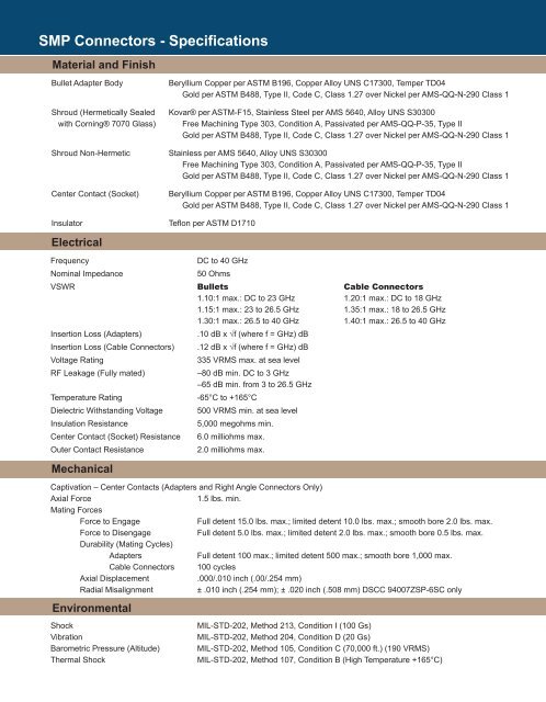
<strong>SMP</strong> <strong>Connectors</strong> - Specifications<br />
Material and Finish<br />
Bullet Adapter Body<br />
Shroud (Hermetically Sealed<br />
with Corning® 7070 Glass)<br />
Shroud Non-Hermetic<br />
Center Contact (Socket)<br />
Insulator<br />
Electrical<br />
Beryllium Copper per ASTM B196, Copper Alloy UNS C17300, Temper TD04<br />
Gold per ASTM B488, Type II, Code C, Class 1.27 over Nickel per AMS-QQ-N-290 Class 1<br />
Kovar® per ASTM-F15, Stainless Steel per AMS 5640, Alloy UNS S30300<br />
Free Machining Type 303, Condition A, Passivated per AMS-QQ-P-35, Type II<br />
Gold per ASTM B488, Type II, Code C, Class 1.27 over Nickel per AMS-QQ-N-290 Class 1<br />
Stainless per AMS 5640, Alloy UNS S30300<br />
Free Machining Type 303, Condition A, Passivated per AMS-QQ-P-35, Type II<br />
Gold per ASTM B488, Type II, Code C, Class 1.27 over Nickel per AMS-QQ-N-290 Class 1<br />
Beryllium Copper per ASTM B196, Copper Alloy UNS C17300, Temper TD04<br />
Gold per ASTM B488, Type II, Code C, Class 1.27 over Nickel per AMS-QQ-N-290 Class 1<br />
Teflon per ASTM D1710<br />
Frequency<br />
DC to 40 GHz<br />
Nominal Impedance<br />
50 Ohms<br />
VSWR Bullets Cable <strong>Connectors</strong><br />
1.10:1 max.: DC to 23 GHz 1.20:1 max.: DC to 18 GHz<br />
1.15:1 max.: 23 to 26.5 GHz 1.35:1 max.: 18 to 26.5 GHz<br />
1.30:1 max.: 26.5 to 40 GHz 1.40:1 max.: 26.5 to 40 GHz<br />
Insertion Loss (Adapters)<br />
.10 dB x √f (where f = GHz) dB<br />
Insertion Loss (Cable <strong>Connectors</strong>) .12 dB x √f (where f = GHz) dB<br />
Voltage Rating<br />
335 VRMS max. at sea level<br />
RF Leakage (Fully mated)<br />
–80 dB min. DC to 3 GHz<br />
–65 dB min. from 3 to 26.5 GHz<br />
Temperature Rating<br />
-65°C to +165°C<br />
Dielectric Withstanding Voltage 500 VRMS min. at sea level<br />
Insulation Resistance<br />
5,000 megohms min.<br />
Center Contact (Socket) Resistance 6.0 milliohms max.<br />
Outer Contact Resistance<br />
2.0 milliohms max.<br />
Mechanical<br />
Captivation – Center Contacts (Adapters and Right Angle <strong>Connectors</strong> Only)<br />
Axial Force<br />
1.5 lbs. min.<br />
Mating Forces<br />
Force to Engage<br />
Full detent 15.0 lbs. max.; limited detent 10.0 lbs. max.; smooth bore 2.0 lbs. max.<br />
Force to Disengage<br />
Full detent 5.0 lbs. max.; limited detent 2.0 lbs. max.; smooth bore 0.5 lbs. max.<br />
Durability (Mating Cycles)<br />
Adapters<br />
Full detent 100 max.; limited detent 500 max.; smooth bore 1,000 max.<br />
Cable <strong>Connectors</strong> 100 cycles<br />
Axial Displacement<br />
.000/.010 inch (.00/.254 mm)<br />
Radial Misalignment<br />
± .010 inch (.254 mm); ± .020 inch (.508 mm) DSCC 94007ZSP-6SC only<br />
Environmental<br />
Shock<br />
Vibration<br />
Barometric Pressure (Altitude)<br />
Thermal Shock<br />
MIL-STD-202, Method 213, Condition I (100 Gs)<br />
MIL-STD-202, Method 204, Condition D (20 Gs)<br />
MIL-STD-202, Method 105, Condition C (70,000 ft.) (190 VRMS)<br />
MIL-STD-202, Method 107, Condition B (High Temperature +165°C)