Hydraulic Pump Drives Catalog - TWG
Hydraulic Pump Drives Catalog - TWG
Hydraulic Pump Drives Catalog - TWG

You also want an ePaper? Increase the reach of your titles
YUMPU automatically turns print PDFs into web optimized ePapers that Google loves.
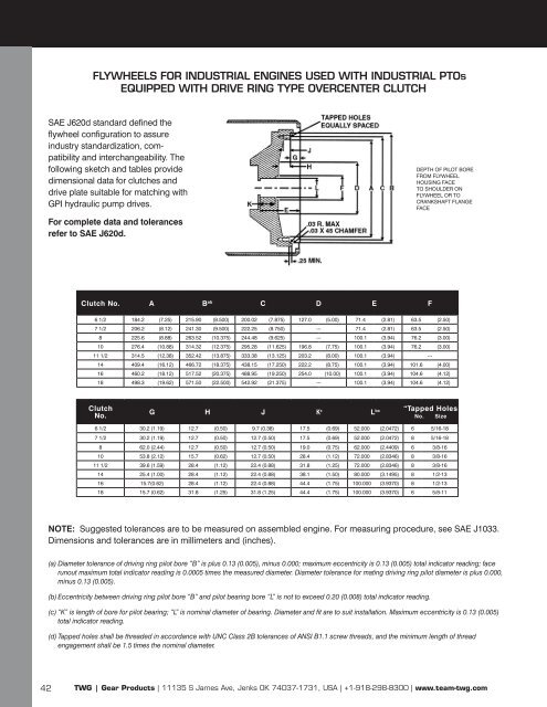
FLYWHEELS FOR INDUSTRIAL ENGINES USED WITH INDUSTRIAL PTOs<br />
EQUIPPED WITH DRIVE RING TYPE OVERCENTER CLUTCH<br />
SAE J620d standard defined the<br />
flywheel configuration to assure<br />
industry standardization, compatibility<br />
and interchangeability. The<br />
following sketch and tables provide<br />
dimensional data for clutches and<br />
drive plate suitable for matching with<br />
GPI hydraulic pump drives.<br />
For complete data and tolerances<br />
refer to SAE J620d.<br />
DEPTH OF PILOT BORE<br />
FROM FLYWHEEL<br />
HOUSING FACE<br />
TO SHOULDER ON<br />
FLYWHEEL OR TO<br />
CRANKSHAFT FLANGE<br />
FACE<br />
Clutch No. A B ab C D E F<br />
6 1/2 184.2 (7.25) 215.90 (8.500) 200.02 (7.875) 127.0 (5.00) 71.4 (2.81) 63.5 (2.50)<br />
7 1/2 206.2 (8.12) 241.30 (9.500) 222.25 (8.750) --- 71.4 (2.81) 63.5 (2.50)<br />
8 225.6 (8.88) 263.52 (10.375) 244.48 (9.625) --- 100.1 (3.94) 76.2 (3.00)<br />
10 276.4 (10.88) 314.32 (12.375) 295.28 (11.625) 196.8 (7.75) 100.1 (3.94) 76.2 (3.00)<br />
11 1/2 314.5 (12.38) 352.42 (13.875) 333.38 (13.125) 203.2 (8.00) 100.1 (3.94) ‐-‐<br />
14 409.4 (16.12) 466.72 (18.375) 438.15 (17.250) 222.2 (8.75) 100.1 (3.94) 101.6 (4.00)<br />
16 460.2 (18.12) 517.52 (20.375) 488.95 (19.250) 254.0 (10.00) 100.1 (3.94) 104.6 (4.12)<br />
18 498.3 (19.62) 571.50 (22.500) 542.92 (21.375) --- 100.1 (3.94) 104.6 (4.12)<br />
Clutch<br />
No.<br />
G H J K c L<br />
“Tapped Holes<br />
bc<br />
No. Size<br />
6 1/2 30.2 (1.19) 12.7 (0.50) 9.7 (0.38) 17.5 (0.69) 52.000 (2.0472) 6 5/16-18<br />
7 1/2 30.2 (1.19) 12.7 (0.50) 12.7 (0.50) 17.5 (0.69) 52.000 (2.0472) 8 5/16-18<br />
8 62.0 (2.44) 12.7 (0.50) 12.7 (0.50) 19.0 (0.75) 62.000 (2.4409) 6 3/8-16<br />
10 53.8 (2.12) 15.7 (0.62) 12.7 (0.50) 28.4 (1.12) 72.000 (2.8346) 8 3/8-16<br />
11 1/2 39.6 (1.59) 28.4 (1.12) 22.4 (0.88) 31.8 (1.25) 72.000 (2.8346) 8 3/8-16<br />
14 25.4 (1.00) 28.4 (1.12) 22.4 (0.88) 38.1 (1.50) 80.000 (3.1495) 8 1/2-13<br />
16 15.7(0.62) 28.4 (1.12) 22.4 (0.88) 44.4 (1.75) 100.000 (3.9370) 8 1/2-13<br />
18 15.7 (0.62) 31.8 (1.25) 31.8 (1.25) 44.4 (1.75) 100.000 (3.9370) 6 5/8-11<br />
NOTE: Suggested tolerances are to be measured on assembled engine. For measuring procedure, see SAE J1033.<br />
Dimen sions and tolerances are in millimeters and (inches).<br />
(a) Diameter tolerance of driving ring pilot bore “B” is plus 0.13 (0.005), minus 0.000; maximum eccentricity is 0.13 (0.005) total indicator reading; face<br />
runout maximum total indicator reading is 0.0005 times the measured diameter. Diameter tolerance for mating driving ring pilot diameter is plus 0.000,<br />
minus 0.13 (0.005).<br />
(b) Eccentricity between driving ring pilot bore “B” and pilot bearing bore “L” is not to exceed 0.20 (0.008) total indicator reading.<br />
(c) “K” is length of bore for pilot bearing; “L” is nominal diameter of bearing. Diameter and fit are to suit installation. Maximum eccentricity is 0.13 (0.005)<br />
total indicator reading.<br />
(d) Tapped holes shall be threaded in accordance with UNC Class 2B tolerances of ANSI B1.1 screw threads, and the minimum length of thread<br />
engagement shall be 1.5 times the nominal diameter.<br />
42 <strong>TWG</strong> | Gear Products | 11135 S James Ave, Jenks OK 74037-1731, USA | +1-918-298-8300 | www.team-twg.com