install - Safe-Air Dowco
install - Safe-Air Dowco
install - Safe-Air Dowco

Create successful ePaper yourself
Turn your PDF publications into a flip-book with our unique Google optimized e-Paper software.
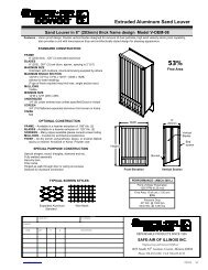
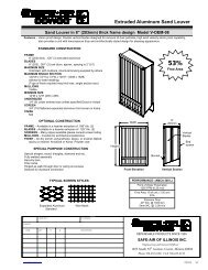
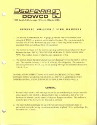
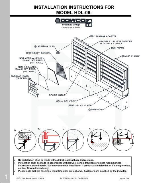
INSTALLATION INSTRUCTIONS FOR<br />
MODEL HDL-06:<br />
Products Group<br />
A division of <strong>Safe</strong> <strong>Air</strong> of Illinois<br />
A. B.<br />
C. D.<br />
E.<br />
<br />
<br />
<br />
No <strong>install</strong>ation shall be made without first reading these instructions.<br />
Installation shall be made in accordance with <strong>Dowco</strong>’s shop drawings or as per recommended<br />
instructions stated herein. (Do not commence <strong>install</strong>ation if products are defective or if damage exists,<br />
contact <strong>Dowco</strong> immediately)<br />
Please note that Sill flashings, mounting clips are optional. Fasteners are supplied by the <strong>install</strong>er.<br />
1 1855 S. 54th Avenue, Cicero, Il. 60804 Tel. 708-652-9100 / Fax 708-652-9158 August 2000
Products Group<br />
A division of <strong>Safe</strong> <strong>Air</strong> of Illinois<br />
LOUVER INSTALLATION INSTRUCTIONS<br />
These are the instructions on how to properly <strong>install</strong> your louver/s. Depending on the actual field condition and manpower, the following are<br />
just minimum recommendations only. The <strong>install</strong>er shall be responsible to fully comply in accordance with the project specifications and the<br />
approved shop drawings and shall be responsible for adding the structural supports if necessary. The <strong>install</strong>er shall be responsible to caulk<br />
the louvers “watertight” before <strong>install</strong>ing them.<br />
RECEIVING/INSPECTION<br />
Upon receiving your louver shipment, inspect the crates carefully. If there is visible damage, contact the freight company immediately so a<br />
freight claim can be filed if necessary. Caution should be used when removing the louvers from the crates. Once uncrated, the louvers<br />
should be checked for proper size, finish, frame style, screen actuator and overall appearance. Any discrepancies should be reported to<br />
DOWCO immediately.<br />
STORAGE<br />
Store in an orderly manner at a safe location away from construction traffic, material, etc. to prevent damage. Cover with plastic sheeting<br />
to protect from excessive moisture, dirt and debris.<br />
PRE-ASSEMBLY<br />
1. Remove the louver from the shipping container and inspect for damage. Care must be taken handling a louver.<br />
Lift by the frame or brace and not by the blade. Do not drop, drag, step on or apply excessive force on louver.<br />
2. Inspect opening where louvers are to be <strong>install</strong>ed. Opening should be ¼” larger or more than louver dimensions plus any<br />
expansion spacing required. If <strong>install</strong>ing adjustable louvers, check the linkage thoroughly and test if blades will open and<br />
close. If problems occur do not <strong>install</strong> them and call DOWCO immediately. Normally, pre-testing is conducted prior to<br />
shipping.<br />
MULTIPLE SECTION ASSEMBLY<br />
1. Position louver sections together. Align and match frame markings or labels on adjacent sections as indicated in the shop<br />
drawings.<br />
2. On multiple section assemblies with visible mullions, <strong>install</strong> the louver section within the t-mullion, align and match frame<br />
markings or labels on adjacent sections. Normally t-mullions are factory mounted to front and back of each sections.<br />
3. Align t-mullions on adjacent frames. Fasten together with self-tapping screws sp. approx. @ 18” o.c. (Note: Field<br />
<strong>install</strong>ation where self-tapping screws are required not supplied by <strong>Dowco</strong>)<br />
4. On multiple section assemblies with invisible mullions, remove all factory-mounted side plates held with screws,<br />
align blades from the exterior side and match frame markings or labels on adjacent sections, fasten the two angles<br />
together with ¼”-20 x 1” lg. HH bolts & nuts leaving 1/8” or more for expansion joint.<br />
5. On multiple stackable section assemblies with concealed mullions in height due to paint size limitation or shipping, splice<br />
plates are factory mounted to the outer side of louver jamb or angle brace, fasten together with self-tapping screws.<br />
6. Use appropriate shims between louver frames and opening structure to prevent distortion of louver frame.<br />
7. Individual sections of multiple assemblies, as well as the entire assembly, must be square and free from racking. Measure<br />
diagonally from upper corners to opposite lower corners of each section. Both dimensions bust equal 1/8 inch + or -.<br />
8. Multiple section louver assemblies may require structural bracing to support the weight of the assembly and specified wind<br />
loads.<br />
RECOMMENDED INSTALLATION OF LOUVERS<br />
1. Louvers must be plumb and square, and <strong>install</strong> within the opening using clips angles or approved equal positioned @ every<br />
18” or 24” on center. Mounting clips must be without pilot holes.<br />
2. Clip angles with self-drilling screws (2 per clip) and extended sills are available as options. Use #10-16 x 1” lg. HWH for selftapping<br />
screws. Wall trim, caulk, and any other fasteners are by others.<br />
2 1855 S. 54th Avenue, Cicero, Il. 60804 Tel. 708-652-9100 / Fax 708-652-9158 August 2000
STEP 1. PREPARATION<br />
MEASURE THE SHORTEST DISTANCE. IF THE ORDERED<br />
SIZE IS GREATER THAN THE LOUVER SIZE. CALL FACTORY<br />
IMMEDIATELY.<br />
1. LOCATE ALL PURCHASED ITEMS AND ORGANIZE<br />
ACCORDING TO PACKAGE LIST OR SCHEDULE.<br />
2. CONFIRM THAT ALL PRODUCTS ARE PRESENT.<br />
3. INSPECT OPENINGS; REPAIR ANY DAMAGES THAT<br />
MAY PROHIBIT THE LOUVER FROM BEING<br />
INSERTED.<br />
4. BE SURE OPENING IS PLUMB AND IS CONSISTENT<br />
WITH THE SIZE OF THE LOUVER.<br />
STEP 2.<br />
SILL FLASHING OR SILL PAN INSTALLATION (IF REQUIRED)<br />
1. APPLY CAULK ONTO SILL OPENING AND INSTALL SILL FLASHING BY<br />
PRESSING DOWN FIRMLY.<br />
2. IF MULTIPLE SILL FLASHINGS ARE REQUIRED, LEAVE ¼” SPACE IN<br />
BETWEEN SILLS.<br />
3. APPLY CAULK ON THE EDGES OF SILLS PER DETAIL “A”<br />
4. PRESS SPLICE PLATE FIRMLY ON TOP OF SILLS THEN SECURE WITH<br />
SCREWS.<br />
A<br />
STEP 3.<br />
MOUNTING CLIP ANGLES<br />
1. REFER TO SHOP DRAWINGS FROM SIZE AND<br />
DETAILS OF MOUNTING CLIP ANGLES.<br />
2. MEASURE THE DISTANCE OF MOUNTING CLIP<br />
ANGLE ACCORDING TO THE REQUIRED SETBACK<br />
FROM THE FACE OF THE WALL.<br />
3. DRILL HOLES INTO WALL TO FIT FOR ANCHORS AT<br />
SPACING PER APPROVED SHOP DRAWINGS OR AT<br />
EVERY 18” OC. USE MIN. #10 SCREWS.<br />
3
STEP 4.<br />
INSTALLING SINGLE LOUVER<br />
1. PLACE LOUVER SECTION INTO OPENING.<br />
2. CHECK EDGES OF PERIMETER TO MEET PROPER<br />
CLEARANCE PER APPROVED DRAWINGS. SHIM<br />
AROUND LOUVER WHERE NECESSARY.<br />
3. MAKE SURE THE LOUVER IS PLUMB AND ONCE<br />
THE PROPER PLACEMENT IS ACHIEVED, SECURE<br />
THE LOUVER USING THE MOUNTING CLIP AT<br />
JAMB, HEAD AND SILL. USE CLIP ANGLES AS A<br />
GUIDE TO DRILL HOLES INTO JAMBS.<br />
4. USE FASTENERS MINIMUM OF #10-16 x 1” FROM<br />
MOUNTING CLIPS TO LOUVER FRAME (2 PER CLIP)<br />
5. IF INSTALLING SINGLE LOUVER PROCEED TO<br />
STEP 7.<br />
STEP 5a.<br />
INSTALLING INVISIBLE MULLIONS<br />
SHOWN FROM BEHIND<br />
1. POSITION LOUVER SECTIONS TOGETHER. ALIGN<br />
AND MATCH FRAME MARKINGS OR LABELS ON<br />
ADJACENT SECTIONS AS INDICATED IN THE<br />
SHOP DRAWINGS.<br />
2. REMOVE ALL FACTORY-MOUNTED SIDE PLATES<br />
HELD WITH SCREWS.<br />
3. START FROM ONE SIDE FAR LEFT OF THE<br />
OPENING ONE COLUMN AT THE TIME.<br />
4. FOR INVISIBLE VERTICAL – FASTEN THE TWO<br />
ANGLES TOGETHER WITH MIN. #12-16 X 1-1/2”<br />
SELF-DRILLING @ 18” OC. LEAVING 1/8” OR MORE<br />
FOR EXPANSION JOINT.<br />
5. FOR INVISIBLE HORIZONTAL – ALIGN JAMBS<br />
TOGETHER USING THE FACTORY INSTALLED<br />
SPLICE PLATES OR ANGLE BRACE, FASTEN<br />
TOGETHER WITH MIN.# 12-16 X 1-1/2 SELF-<br />
DRILLING SCREWS.<br />
INVISIBLE HORIZONTAL<br />
INVISIBLE VERTICAL<br />
STEP 5b.<br />
INSTALLING VISIBLE MULLIONS<br />
4<br />
1. POSITION LOUVER SECTIONS TOGETHER. ALIGN<br />
AND MATCH FRAME MARKINGS OR LABELS ON<br />
ADJACENT SECTIONS AS INDICATED IN THE SHOP<br />
DRAWINGS.<br />
2. START FROM ONE SIDE FAR LEFT OF THE OPENING<br />
ONE COLUMN AT THE TIME. NORMALLY T-MULLIONS<br />
ARE FACTORY INSTALLED TO FRONT AND BACK OF<br />
EACH SECTION.<br />
3. FOR VISIBLE VERTICAL - FASTEN THE SECTIONS<br />
TOGETHER THROUGH T-MULLION WITH MIN.# 10-16 X<br />
1 SELF-DRILLING SCREW @ 18” OC.<br />
4. FOR VISIBLE HORIZONTAL - INSTALL THE BOTTOM<br />
SECTION IN PLACE FIRST THEN CAULK THE HEAD TO<br />
RECEIVE THE T-MULLION OF THE UPPER SECTION,<br />
FASTEN TOGETHER WITH MIN. # 10-16 X 1 SELF-<br />
DRILLING SCREW @ 18” OC.<br />
VISIBLE HORIZONTAL<br />
VISIBLE VERTICAL
STEP 6.<br />
SILL SPLICE COVER<br />
1. LOCATE SILL FRAMES WITH INVISIBLE<br />
MULLION.<br />
2. APPLY A LAYER OF CAULK LEFT AND<br />
RIGHT BENEATH THE SPLICE COVER<br />
3. FASTEN THE SPLICE COVER TO SILL<br />
FRAMES TO HOLD IN PLACE.<br />
STEP 7.<br />
CAULKING<br />
1. AFTER THE LOUVER SECTIONS ARE IN PLACE AND<br />
SECURED, MAKE SURE THE LOUVERS ARE PLUMB.<br />
2. PLACE A BACKER ROD AND CAULK ALL AROUND THE<br />
PERIMETER OF THE LOUVER WITH THE SAME COLOR AS<br />
THE LOUVERS<br />
B<br />
Please call your Sales Representative if<br />
you have further questions or problems.<br />
5<br />
Products Group<br />
A division of <strong>Safe</strong> <strong>Air</strong> of Illinois<br />
1855 S. 54th Avenue, Cicero, Il. 60804 Tel. 708-652-9100 / Fax 708-652-9158 August 2000